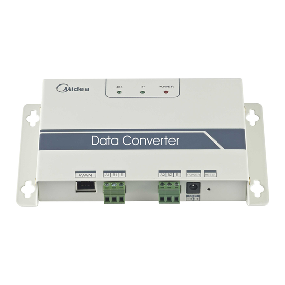
Bosch CLIMATE 5000 VRF BMS-MOD Installation & User Manual
Building management system gateway card (modbus)
Hide thumbs
Also See for CLIMATE 5000 VRF BMS-MOD:
- Installation manual (36 pages) ,
- Installation & user manual (24 pages) ,
- Installation and user manual (16 pages)
Summary of Contents for Bosch CLIMATE 5000 VRF BMS-MOD
- Page 1 CLIMATE 5000 VRF Building Management System Gateway Card (Modbus) BMS-MOD Installation-user manual Before using your air conditioning system, please read this manual carefully and keep it for future reference. 6720862468 (16/04) CLIMATE 5000 VRF...
-
Page 2: Table Of Contents
Contents Safety precautions ............3 Overview ...............3 Usage Introduction ............5 Software Reset ............11 Appendix Mapping Table ..........11 6720862468 (16/04) CLIMATE 5000 VRF... -
Page 3: Safety Precautions
Safety precautions | 3 Safety precautions The following contents are stated on the product and the operation manual, including usage, precautions against injury and property loss, and the methods of using the product correctly and safely. After fully understanding the following contents (identifiers and icons), read the text body and observe the following rules. ■... - Page 4 4 | Overview 2.2. System Architecture Description It supports two kinds of outdoor unit with baud rates of 600 and 4800. (For detailed information, please contect our technical support). The addresses of accessed indoor/outdoor units can’t repeat. 1) When the baud rate of the outdoor unit is 600, 64 indoor units and 4 outdoor units can connect to it at once. 2) When the baud rate of the outdoor unit is 4800, 60 indoor (with the address from 4—63) units and 4 outdoor units can connect to it at most.
-
Page 5: Usage Introduction
Usage Introduction | 5 2.3. Function Code Function code Function name Function 0x01 Read Coils Read 0x04 Read Input Register Read 0x10 Write Holding Register Write 2.4. Abnormal Reply The master unit sends requests and waits for reply from the slave.When there’s no error occurs, the slave will reply normally, but when there’s data checking error, the slave won’t answer. - Page 6 6 | Usage Introduction 1.1.2. Multi-IP Addition Configure a static IP address before adding multiple IP. Open protocol dialog and choose Advanced tab. TCP/IP setting dialog will display like below: Fig.3.2 Click “Add” in IP address bar to add an IP address which is in the same segment as “192.168.1.200”, e.g., IP: 192.168.1.209 subnet mask 255.255.255.0 and click “OK”...
- Page 7 Usage Introduction | 7 Parameters Setting: Parameter Description Modbus ID, to distinguish modbus gateway with multiple Modbus address Modbus protocols in the same subnet. Don’t repeat the address. Baud rate: suggest 9600 Modbus commu- Check bit: no checking by default nication setting Stop bit: 1StopBit by default IP address of modbus gateway, multiple IPs can’t be the same.
- Page 8 8 | Usage Introduction When click the address number of the indoor or outdoor unit, it will show corresponding operation information of the air conditioner. The chosen device will display in the red frame. When click “input register”, the interface will be like this: Fig.3.5 The first column is the address, second is the content and the third is displayed value, e.g.
- Page 9 Usage Introduction | 9 Air Conditioner Control When click “Air Conditioner Control” on the web page, it will display like this: Single Air Conditioner Control Area Group control of cooling system Fig.3.6 Single air conditioner control area: control the single air conditioner. Choose a single air conditioner and set mode, fan speed and temperature. Single control area: to choose a single air conditioner, set mode, fan speed, temperature and click “Apply”...
- Page 10 10 | Usage Introduction Fig.3.7 1.1.4.2. Connect Modbus Gateway There’re 2 connection ways: Modbus TCP and Modbus RTU 1) Choose ”Connection”->”Connection” in figure 3.7,and then chose TCP/IP in the pop-up window: To choose a connection Connection terminal: IP address for 502 by default connection Fig.3.8...
-
Page 11: Software Reset
Software Reset | 11 Modbus address Initial address needed to check Address length Click the “OK” button and it will display the content. If the content is the same as the value of the web page which has the same address, it means that the software debugging is complete. - Page 12 Bosch Thermotechnology Ltd. CotswoldWay, Warndon, Worcester WR4 9SW All Enquiries: 0330 123 3004 www.bosch-industrial.co.uk...


