
Related Manuals for YASKAWA VIPA TP


Summary of Contents for YASKAWA VIPA TP
- Page 1 VIPA HMI TP | 62F-FEE0 | Manual HB160 | TP | 62F-FEE0 | en | 17-25 Touch Panel - TP605CQ www.vipa.com/en/service-support/manuals...
- Page 2 VIPA GmbH Ohmstr. 4 91074 Herzogenaurach Telephone: +49 9132 744-0 Fax: +49 9132 744-1864 Email: info@vipa.com Internet: www.vipa.com 62F-FEE0_000_TP605CQ,3,EN - © 2017...
-
Page 3: Table Of Contents
VIPA HMI Table of contents Table of contents General........................4 1.1 Copyright © VIPA GmbH ................. 4 1.2 About this manual..................... 5 1.3 Safety information..................... 6 Hardware description..................... 7 2.1 Safety information for users................7 2.2 Properties......................8 2.3 Structure......................9 2.3.1 Overview...................... -
Page 4: General
VIPA HMI General Copyright © VIPA GmbH General 1.1 Copyright © VIPA GmbH All Rights Reserved This document contains proprietary information of VIPA and is not to be disclosed or used except in accordance with applicable agreements. This material is protected by the copyright laws. It may not be reproduced, distributed, or altered in any fashion by any entity (either internal or external to VIPA), except in accord- ance with applicable agreements, contracts or licensing, without the express written con- sent of VIPA and the business management owner of the material. -
Page 5: About This Manual
VIPA HMI General About this manual VIPA GmbH, Ohmstraße 4, 91074 Herzogenaurach, Germany Telefax: +49 9132 744-1204 EMail: documentation@vipa.de Technical support Contact your local VIPA Customer Service Organization representative if you encounter problems with the product or have questions regarding the product. If you are unable to locate a customer service centre, contact VIPA as follows: VIPA GmbH, Ohmstraße 4, 91074 Herzogenaurach, Germany Tel.: +49 9132 744-1150 (Hotline) -
Page 6: Safety Information
VIPA HMI General Safety information Supplementary information and useful tips. 1.3 Safety information Applications conforming The Touch Panels are constructed and produced for: with specifications VIPA CPUs 01x, 11x, 21x, 31x, 51x and S7-300/400 from Siemens communication and process control industrial applications operation within the environmental conditions specified in the technical data installation into a cubicle... -
Page 7: Hardware Description
VIPA HMI Hardware description Safety information for users Hardware description 2.1 Safety information for users Handling of electrostatic VIPA modules make use of highly integrated components in MOS-Technology. These sensitive modules components are extremely sensitive to over-voltages that can occur during electrostatic discharges. -
Page 8: Properties
VIPA HMI Hardware description Properties 2.2 Properties General The VIPA Touch Panel allows you to visualize and alter operating states and recent process values of a connected PLC. The Touch Panel is a compact and modular Ò Ò embedded PC based on Windows CE. -
Page 9: Structure
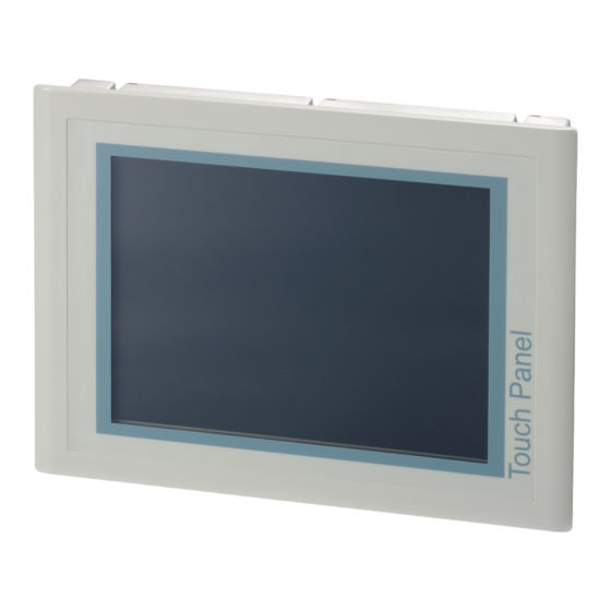
VIPA HMI Hardware description Structure > Overview Order data Type Order number Description TP 605CQ 62F-FEE0-... 5.7" TFT color, MPI/PROFIBUS DP/RS485, RS232, RS422/485, USB-A, USB-B, Ethernet RJ45 2.3 Structure 2.3.1 Overview Front view Slot for storage medium (CF, SD/MMC) Connection for interfaces and power supply Display with touch sensitive area (touch screen) Side view Compact Flash... -
Page 10: Interfaces
VIPA HMI Hardware description Structure > Interfaces Bottom view (Interfaces) RS422/485 interface COM 2 RS232 interface COM 1 MPI/PROFIBUS DP/RS485 interface "Host"-USB-A interface "Slave"-USB-B interface RJ45 jack for Ethernet communication Slot for DC 24V voltage supply Slot for CF/SD/MMC storage medium Please make sure that the Touch Panel always has to be supplied with external voltage! 2.3.2 Interfaces... - Page 11 VIPA HMI Hardware description Structure > Interfaces RS422/485 interface 9 pin SubD jack Logical states represented by voltage differences between the 4 cores Serial bus connection in 4-wire technology using full duplex mode Data communications up to a max. distance of 500m Data communication rate up to 115.2kBaud Serial bus connection in 2-wire technology using half duplex mode RS232 interface...
-
Page 12: Memory Management
VIPA HMI Hardware description Structure > Memory management MPI/PROFIBUS DP inter- 9 pin SubD jack face Ethernet connection An RJ45 jack provides the interface to the twisted pair cable, required for Ethernet. "Host"-USB-A Using the "Host"-USB-A interface USB mouse, keyboard, stick or USB hard discs can be connected. - Page 13 VIPA HMI Hardware description Structure > Memory management Micro-SD card As internal permanent storage medium every Touch Panel has a Micro-SD card with a Ò size of 2Gbyte (about 1800Mbyte user data). After the start of Windows CE this memory is listed as SDMMC Card under My Device.
-
Page 14: Dimensions
VIPA HMI Hardware description Dimensions 2.4 Dimensions Installation dimensions For the installation of the Touch Panel in control cabinets and desks the following dimen- sions are necessary: 5.7" - 62F-FEE0-... Front panel width 2.5 ... 6mm Installation cutting (W x H) 200 x 144mm Front panel (W x H) 212 x 156mm... -
Page 15: General Data
VIPA HMI Hardware description General data 2.5 General data Conformity and approval Conformity 2014/35/EU Low-voltage directive 2014/30/EU EMC directive Approval Refer to Technical data others RoHS 2011/65/EU Restriction of the use of certain hazardous substances in electrical and electronic equipment Protection of persons and device protection Type of protection IP20... -
Page 16: Technical Data
VIPA HMI Hardware description Technical data > 62F-FEE0-CB Standard Comment Emitted interference EN 61000-6-4 Class A (Industrial area) Noise immunity EN 61000-6-2 Industrial area zone B EN 61000-4-2 8kV at air discharge (degree of severity 3), 4kV at contact discharge (degree of severity 2) EN 61000-4-3 HF field immunity (casing) 80MHz …... - Page 17 VIPA HMI Hardware description Technical data > 62F-FEE0-CB Order no. 62F-FEE0-CB CF Card Slot Typ II ü CFast Slot Time Real-time clock buffered ü Clock buffered period (min.) Type of buffering Vanadium Rechargeable Lithium Battery Load time for 50% buffering period 10 h Load time for 100% buffering period 48 h...
-
Page 18: Fee0-Cx
VIPA HMI Hardware description Technical data > 62F-FEE0-CX Order no. 62F-FEE0-CB Current consumption (rated value) 0.45 A Inrush current I²t 0.2 A²s Power loss 6.2 W Status information, alarms, diagnostics Supply voltage display Mechanical data Housing / Protection type Material die-cast aluminum Mounting via integrated pivoted lever... - Page 19 VIPA HMI Hardware description Technical data > 62F-FEE0-CX Order no. 62F-FEE0-CX Resolution 240 x 320 / 320 x 240 Aspect ratio Type of display TFT color (64K colors) MTBF Backlights (25°C) 50000 h System properties Processor Xscale 800 MHz Operating system Windows CE 6.0 Prof.
- Page 20 VIPA HMI Hardware description Technical data > 62F-FEE0-CX Order no. 62F-FEE0-CX USB-B connector USB-B (device) Number of ethernet interfaces Ethernet Ethernet 10/100 MBit Ethernet connector RJ45 Integrated ethernet switch Video connectors Audio connections Technical data power supply Power supply (rated value) DC 24 V Power supply (permitted range) DC 20.4...28.8 V...
- Page 21 VIPA HMI Hardware description Technical data > 62F-FEE0-CX Order no. 62F-FEE0-CX Certifications UL certification in preparation KC certification HB160 | TP | 62F-FEE0 | en | 17-25...
-
Page 22: Deployment Touch Panel
VIPA HMI Deployment Touch Panel Installation Deployment Touch Panel 3.1 Installation Overview The Touch Panel is suitable for the installation in operating tables and control cabinet fronts. The installation happens via the back. The Touch Panel is provided with a patented integrated fixing technique that allows an easy connection with a simple screw- driver. - Page 23 VIPA HMI Deployment Touch Panel Installation Connect power supply For the cabling of the DC 24V power supply green plugs with CageClamp technology are deployed. The spring-clip connector technology simplifies the wiring requirements for sig- naling and power cables. In contrast to screw terminal connections, spring-clip wiring is vibration proof.
-
Page 24: Commissioning
VIPA HMI Deployment Touch Panel Commissioning > VIPA Startup-Manager 3.2 Commissioning CAUTION! – Before commissioning the device must be brought to room tempera- ture. – At condensation the device must be absolutely dry before connected to power. – To avoid overheat during operation the device must not be laid open to direct sun light. - Page 25 VIPA HMI Deployment Touch Panel Commissioning > VIPA Startup-Manager Panel Info Here you get information about Touch Panel such as operating system, images runtime version and tools. Normal With this button you can return to the user area. Control Panel With the button [Control Panel] or via ‘Start è...
- Page 26 VIPA HMI Deployment Touch Panel Commissioning > VIPA Startup-Manager It is possible to set up the DP slave with the tool via software if the hard- ware of the Touch Panel does not support this. In this case MPI does not work either.
- Page 27 VIPA HMI Deployment Touch Panel Commissioning > VIPA Startup-Manager Custom Here new buttons can be configured and assigned with corresponding programmes. Choose "Normal" for the user area or "Advanced" for the administrator area. With [+] a new button can be added. Designate the button and click on [...] to assign the button to a program.
- Page 28 VIPA HMI Deployment Touch Panel Commissioning > VIPA Startup-Manager Copy Here with the startup of the panel files can be copied e.g. from flash disk to Win- Ò dows Files can be added by [+]. With [-] the corresponding file is removed from the list. With [...] the file can be downloaded.
- Page 29 VIPA HMI Deployment Touch Panel Commissioning > VIPA Startup-Manager About Here you can find the current version of the Startup-Manager. Ò Exit The Startup Manager is closed by [Exit] and the system returns to the Windows oper- ating system. HB160 | TP | 62F-FEE0 | en | 17-25...
-
Page 30: Connection To A Plc System
VIPA HMI Deployment Touch Panel Operating system WindowsÒ Embedded CE 6.0 Prof. > General 3.3 Connection to a PLC system Overview For the inclusion into your PLC system several HMI/SCADA project-engineering platforms are at your disposal that has to be installed at an external PC. Here you may create your project, where appropriate simulate it and transfer it to the Touch Panel via a connection that you’ve entered before. - Page 31 VIPA HMI Deployment Touch Panel Operating system WindowsÒ Embedded CE 6.0 Prof. > General Properties ftp, http, Telnet and VNC server RAS server ActiveSync file transfer (USB, RS232) RDP (Remote Desktop Protocol) Internet Explorer 6 Registry Editor WordPad Mouse pointer USB keyboard driver HP printer driver (COM, Ethernet, USB) File viewer for Word, Excel, PowerPoint and PDF...
-
Page 32: Structure
VIPA HMI Deployment Touch Panel Operating system WindowsÒ Embedded CE 6.0 Prof. > Structure 3.4.2 Structure Icon Via icons on the desktop you gain direct access to the application related to the icon. Desktop Ò The desktop is the screen that is shown after login to Windows CE. - Page 33 VIPA HMI Deployment Touch Panel Operating system WindowsÒ Embedded CE 6.0 Prof. > Structure Show desktop All windows are minimized and the desktop is shown. Software keyboard This button displays a keyboard on the screen. "Hide Input Panel" hides the key- board again.
- Page 34 VIPA HMI Deployment Touch Panel Operating system WindowsÒ Embedded CE 6.0 Prof. > Structure Large KB At pushed Shift key: Meaning Home Position 1 End End BS Backspace up ã dn ä lt á rt â pgup Page ã pgdn Page ä ins Insert del Delete Tab Tabulator...
- Page 35 VIPA HMI Deployment Touch Panel Operating system WindowsÒ Embedded CE 6.0 Prof. > Structure Ò System setting (Control As many components of the Control Panel conform with the system control of Windows Panel) most of the description is not necessary. The description of the control panel components relevant for operating the Touch Panel can be found in the following: Set display Via ‘Start è...
-
Page 36: Communication Via Activesync
VIPA HMI Deployment Touch Panel Communication via ActiveSync Default Net Parameters It is recommended not to alter the Default Net Parameters that are set by the baud rate. Status The status of the MPI interface is monitored via Status as "Offline", "Online" or "Error". - Page 37 VIPA HMI Deployment Touch Panel Communication via ActiveSync Install partnership for USB Now you can install a "partnership" via an USB connection with the following approach: communication Connect your Touch Panel via the "Device"-USB-B jack to your PC and turn on the Touch Panel.
-
Page 38: Integrated Server
VIPA HMI Deployment Touch Panel Integrated Server > ftp server [Finish] establishes the partnership. Now you can access the Touch Panel with ActiveSync via USB. To keep the settings also after power on, you have to store them to the registry with ‘START è... -
Page 39: Http Server
VIPA HMI Deployment Touch Panel Integrated Server > http server Conditions for ftp access Depending on the ftp client your PC must have the following conditions for a ftp connec- tion. If there are still problems with the ftp access please ask your system administrator. Internet Explorer ftp access possible with version 5.5 or higher activate directory view for ftp sites... -
Page 40: Telnet Server
VIPA HMI Deployment Touch Panel Integrated Server > Telnet server Web admin As web admin you have access to all functions that are required for uploading and admin- istrating of websites on the Touch Panel. Additionally you may set the access rights for user and create user groups. -
Page 41: Vnc Server
VIPA HMI Deployment Touch Panel Integrated Server > VNC server 3.6.5 VNC server The Touch Panel has an integrated VNC server (virtual network control) that allows the total control of the Touch Panel with a PC via network. For this, a window displays the current Touch Panel content for remote control. -
Page 42: Access To The Network Resources
VIPA HMI Deployment Touch Panel Access to the network resources Click on [Options] and deactivate the field "Emulate 3 Buttons..." like shown at Mouse. Enter the IP address of the Touch Panel at VNC server. Click on [OK] and enter the password vipatp. - Page 43 VIPA HMI Deployment Touch Panel Access to the network resources For example net view testserver lists all shared resources of the network PC "test server". To test the physical connection a PING to the IP address of the network PC can be executed if there are problems while contacting the network PC.
-
Page 44: Firmware Update
VIPA HMI Deployment Touch Panel Firmware update Terminate network con- You can terminate already assigned network resources via nections \> net use local_name /d Example: \> net use data /d deletes the network connection to the drive "archive" of "test server". To save the settings also after power on, you have to store them to the registry with ‘START è... - Page 45 VIPA HMI Deployment Touch Panel Firmware update Perform a re-calibration of the touch screen and save your settings with the KuK Tools via ‘Start è Start è Programs è KuK_Tools è KuK Tools’ [Store]. More Ò concerning the calibration can be found under "System settings" of the Windows CE description.
-
Page 46: Installation Guidelines
VIPA HMI Installation Guidelines Basic rules for the EMC-equitable assembly of installations Installation Guidelines 4.1 Basic rules for the EMC-equitable assembly of installations General The installation guidelines contain information about the interference free deployment of a PLC system. There is the description of the ways, interference may occur in your PLC, how you can make sure the electromagnetic compatibility (EMC), and how you manage the isolation. - Page 47 VIPA HMI Installation Guidelines Basic rules for the EMC-equitable assembly of installations Coupling mechanism Cause Typical source Capacitate coupling Capacitate or electric coupling occurs Interference through parallel signal between conductors with different lines potential. The coupling is propor- Static discharge of the personnel tionate to the temporal change of the Contactors voltage.
- Page 48 VIPA HMI Installation Guidelines Basic rules for the EMC-equitable assembly of installations Proof the correct fixing of the lead isolation. – Data lines must be laid isolated. – Analog lines must be laid isolated. When transmitting signals with small ampli- tudes the one sided laying of the isolation may be favourable.
-
Page 49: Emc-Equitable Assembly
VIPA HMI Installation Guidelines EMC-equitable assembly 4.2 EMC-equitable assembly Mostly, measures for suppressing interference voltages are only taken, when the control is already in commission and the perfect receive of a wanted signal is disturbed. Causes for such interference's are in the most cases inadequate reference potentials, coming from mistakes at the device assembly and installation. -
Page 50: Emc-Equitable Cabling
VIPA HMI Installation Guidelines EMC-equitable cabling 4.3 EMC-equitable cabling Line routing Content of this section is the line routing of bus, signal and supply lines. Object of the line routing is to suppress the "slurring" at parallel lines. Line routing inside and For an EMC-equitable routing of the lines it is convenient to divide the cables in different outside of cubicles groups and install each group itself:... - Page 51 VIPA HMI Installation Guidelines EMC-equitable cabling Lightning protection CAUTION! Where cables and signal lines for PLC equipment are installed outside of buildings, the conditions for internal and external lightning protection must be satisfied. – Exterior lines should either be installed in metallic conduit pipes that is grounded on both ends or in steel-reinforced concrete cable trunks with continuously connected reinforcing.
- Page 52 VIPA HMI Installation Guidelines EMC-equitable cabling Avoid cables with foil-type screens as the foil can be easily damaged by tension and pressure at the point of attachment; this can result in reduced effectiveness of the screening action. As a rule you should always ground the screens of cables on both ends. This is the only way in which you can ensure that high frequency interference is attenuated prop- erly.
-
Page 53: Special Precautions Providing High Noise Immunity
VIPA HMI Installation Guidelines Special precautions providing high noise immunity 4.4 Special precautions providing high noise immunity Inductors require snubber Inductors controlled by your programmable controller (e.g. contactors and relays) do not networks normally require additional snubber networks or suppressors as the respective modules have been provided with the required components. -
Page 54: Checklist For The Emc-Compliant Installation Of Controllers
VIPA HMI Installation Guidelines Checklist for the EMC-compliant installation of controllers 4.5 Checklist for the EMC-compliant installation of controllers EMV-measures Space for Notes Connection of the inactive parts You should take special care to check the connections of: Module racks Frames Screen and protected earth conductor Are all the inactive metal parts interconnected by means of large-surface and low-...