Table of Contents
Advertisement
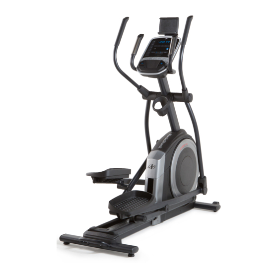
Model No. NTEVEL69818.0
Serial No.
USER'S MANUAL
Write the serial number in the space
above for reference.
Serial Number
Decal
CUSTOMER SERVICE
UNITED KINGDOM
Call: 0330 123 1045
From Ireland: 053 92 36102
Website: iconsupport.eu
E-mail: csuk@iconeurope.com
Write:
ICON Health & Fitness, Ltd.
Unit 4, Westgate Court
Silkwood Park
OSSETT
WF5 9TT
UNITED KINGDOM
AUSTRALIA
Call: 1800 993 770
E-mail: australiacc@iconfitness.com
Write:
ICON Health & Fitness
PO Box 635
WINSTON HILLS NSW 2153
AUSTRALIA
CAUTION
Read all precautions and
instructions in this manual before
using this equipment. Keep this
manual for future reference.
iconeurope.com
Advertisement
Table of Contents

Related Manuals for NordicTrack C 5.5


Summary of Contents for NordicTrack C 5.5
- Page 1 Model No. NTEVEL69818.0 Serial No. USER’S MANUAL Write the serial number in the space above for reference. Serial Number Decal CUSTOMER SERVICE UNITED KINGDOM Call: 0330 123 1045 From Ireland: 053 92 36102 Website: iconsupport.eu E-mail: csuk@iconeurope.com Write: ICON Health & Fitness, Ltd. Unit 4, Westgate Court Silkwood Park OSSETT...
-
Page 2: Table Of Contents
NORDICTRACK and IFIT are registered trademarks of ICON Health & Fitness, Inc. App Store is a trademark of Apple Inc., registered in the U.S. and other countries. Android and Google Play are trademarks of Google LLC. -
Page 3: Important Precautions
IMPORTANT PRECAUTIONS WARNING: To reduce the risk of serious injury, read all important precautions and instructions in this manual and all warnings on your elliptical before using your elliptical. ICON assumes no responsibility for personal injury or property damage sustained by or through the use of this product. -
Page 4: Before You Begin
Thank you for selecting the revolutionary reading this manual, please see the front cover of this NORDICTRACK C 5.5 elliptical. The C 5.5 elliptical manual. To help us assist you, note the product model ® provides an impressive selection of features designed number and serial number before contacting us. -
Page 5: Part Identification Chart
PART IDENTIFICATION CHART Use the drawings below to identify the small parts needed for assembly. The number in parentheses below each drawing is the key number of the part, from the PART LIST near the end of this manual. The number following the key number is the quantity needed for assembly. -
Page 6: Assembly
ASSEMBLY • Assembly requires two persons. • In addition to the included tool(s), assembly requires the following tools: • Place all parts in a cleared area and remove the one Phillips screwdriver packing materials. Do not dispose of the packing materials until you finish all assembly steps. - Page 7 3. With the help of a second person, place some of the packing materials (not shown) under the front of the Frame (1). Have the second per- son hold the Frame to prevent it from tipping while you complete this step. Attach the Front Stabilizer (6) to the Frame (1) with two M10 x 115mm Screws (104).
- Page 8 5. Tip: Avoid pinching the Upper Wire (110). Have a second person hold the Upright (4) on the Frame (1). Avoid pinching the Tip: Two M10 x 25mm Screws (92) are Upper Wire (110) preattached to the Frame (1). Attach the Upright (4) to the Frame (1) with two additional M10 x 25mm Screws (92);...
- Page 9 7. Apply grease to the axle on the right side of the Upright (4). Next, slide a Pivot Spacer (54) onto the right side of the Upright (4). Then, identify the Right Upper Body Leg (60), orient it as shown, and slide it onto the right side of the Upright (4).
- Page 10 9. Apply grease to one of the Pedal Arm Axles (64). Insert the Pedal Arm Axle (64) into the Right Upper Body Leg (60) and the Right Pedal Arm (58) from the direction shown. Next, slide an M8 x 22mm Washer (129) onto an M8 x 13mm Screw (82), and tighten the Screw a few turns into the Pedal Arm Axle (64).
- Page 11 11. Orient the Rear Console Cover (80) as shown, and attach it to the Upright (4) with two M4 x 16mm Screws (101). Then, orient the Front Console Cover (79) as shown, and attach it to the Rear Console Cover (80) with two M4 x 16mm Screws (101).
- Page 12 13. Orient a Lower Tray Cover (81) as shown, and attach it to the right side of the Accessory Tray (37) with two M4 x 16mm Screws (101). Repeat this step on the other side of the elliptical. 14. Identify the Right Upper Body Arm (61), orient it as shown, and slide it onto the Right Upper Body Leg (60).
- Page 13 15. Orient the Front Shield Cover (117) and the Center Shield Cover (75) around the Upright (4) as shown. Then, attach them to each other with two M4 x 16mm Screws (101). Then, press the Front Shield Cover (117) and the Center Shield Cover (75) into the Left and Right Shields (73, 74).
- Page 14 17. Orient the Right Arm Front and Rear Covers (65, 66) around the Right Upper Body Leg (60) as shown, and then attach them with two M4 x 16mm Screws (101). Repeat this step on the other side of the elliptical.
- Page 15 19. Plug the Power Adapter (119) into the receptacle on the frame of the elliptical. Note: To plug the Power Adapter (119) into an outlet, see HOW TO PLUG IN THE POWER ADAPTER on page 16. 20. Make sure that all parts are properly tightened before you use the elliptical. Place a mat beneath the elliptical to protect the floor.
-
Page 16: How To Use The Elliptical
HOW TO USE THE ELLIPTICAL HOW TO PLUG IN THE POWER ADAPTER HOW TO MOVE THE ELLIPTICAL IMPORTANT: If the elliptical has been exposed to Due to the size and weight of the elliptical, moving cold temperatures, allow it to warm to room tem- it requires two persons. - Page 17 HOW TO USE THE TABLET HOLDER HOW TO EXERCISE ON THE ELLIPTICAL IMPORTANT: The tablet holder (G) is designed To mount the elliptical, hold the handlebars (J) or the for use with most full-size tablets. Do not place upper body arms (K) and step onto the pedal (L) that is any other electronic device or object in the tablet in the lower position.
- Page 18 CONSOLE DIAGRAM FEATURES OF THE CONSOLE resistance of the pedals and prompts you to maintain a target pedaling speed as it guides you through an The advanced console offers an array of features effective workout. designed to make your workouts more effective and enjoyable.
- Page 19 HOW TO USE THE MANUAL MODE 4. Follow your progress with the displays. 1. Begin pedaling or press any button on the The display can show the following workout console to turn on the console. information: When you turn on the console, the display will turn Calories (CALS)—When the manual mode and on.
- Page 20 Press the Next Display button repeatedly to view To change the volume the desired workout information in the display. level of the console, press the volume increase and decrease buttons. To pause the console, simply stop pedaling. When the console is paused, the time will flash in the Scan mode—The console also has a scan mode display.
- Page 21 HOW TO USE AN ONBOARD WORKOUT When your pulse is detected, your heart rate will be shown in the display. For the most accurate heart rate reading, hold the contacts for at least 15 1. Begin pedaling or press any button on the seconds.
- Page 22 IMPORTANT: The target speed is intended only HOW TO USE THE SOUND SYSTEM to provide motivation. Your actual pedaling speed may be slower than the target speed. To play music or audio books through the console Make sure to pedal at a speed that is comfort- sound system while you exercise, plug a 3.5 mm male able for you.
- Page 23 HOW TO CONNECT YOUR TABLET TO THE 5. Disconnect your tablet from the console if CONSOLE desired. The console supports BLUETOOTH connections To disconnect your tablet from the console, first to tablets via the iFit–Smart Cardio Equipment app select the disconnect option in the iFit–Smart and to compatible heart rate monitors.
- Page 24 HOW TO CHANGE CONSOLE SETTINGS Button Test—This screen is intended to be used by service technicians to identify whether a certain 1. Select the settings mode. button is working correctly. Total Time—The word TIME will appear in the If you are using the manual mode or an onboard workout, you must stop pedaling and exit the work- display.
- Page 25 Demo Mode—The currently selected demo mode 4. Exit the settings mode. option will appear in the display. The console features a demo mode, designed to be used if the Press the Settings button to exit the settings mode. elliptical is displayed in a store. If the demo mode is turned on, the console will not turn off and the display will not be reset when you finish exercising.
-
Page 26: Maintenance And Troubleshooting
MAINTENANCE AND TROUBLESHOOTING MAINTENANCE If a replacement power adapter is needed, call the telephone number on the cover of this manual. Regular maintenance is important for optimal IMPORTANT: To avoid damaging the console, use only a manufacturer-supplied regulated power performance and to reduce wear. Inspect and properly adapter. - Page 27 HOW TO ADJUST THE REED SWITCH Next, slightly loosen the indicated two M4 x 12mm Self-tapping Screws (50). Slide the Reed Switch (38) If the console does not display correct feedback, the slightly closer to or away from the Magnet (43), and reed switch should be adjusted.
- Page 28 HOW TO ADJUST THE DRIVE BELT Next, locate and loosen the If the pedals slip while you are pedaling, even while Idler Screw (89). the resistance is adjusted to the highest level, the drive Tighten the Drive belt may need to be adjusted. To adjust the drive belt, Belt Adjustment first unplug the power adapter.
-
Page 29: Exercise Guidelines
EXERCISE GUIDELINES Burning Fat—To burn fat effectively, you must exer- WARNING: cise at a low intensity level for a sustained period of Before beginning this time. During the first few minutes of exercise, your or any exercise program, consult your physi- body uses carbohydrate calories for energy. - Page 30 SUGGESTED STRETCHES The correct form for several basic stretches is shown at the right. Move slowly as you stretch; never bounce. 1. Toe Touch Stretch Stand with your knees bent slightly and slowly bend forward from your hips. Allow your back and shoulders to relax as you reach down toward your toes as far as possible.
-
Page 31: Part List
PART LIST Model No. NTEVEL69818.0 R0818A Key No. Qty. Description Key No. Qty. Description Frame/Ramp Roller Rear Stabilizer Pedal Arm Cap Access Cover Axle Cover Upright Pivot Spacer M4 x 19mm Screw Retainer Front Stabilizer Roller Arm Bushing Console Large Arm Bearing Roller Guide Right Pedal Arm Crank Bearing Spacer... - Page 32 Key No. Qty. Description Key No. Qty. Description M4 x 16mm Screw M8 x 20mm Flat Head Screw M8 Locknut Latch Axle M6 x 12mm Screw Pin Spring M10 x 115mm Screw Small Arm Bearing M4 x 25mm Self-tapping Screw M4 x 16mm Machine Screw Bottom Ramp Cover Snap Ring...
-
Page 33: Exploded Drawing
EXPLODED DRAWING A Model No. NTEVEL69818.0 R0818A... - Page 34 EXPLODED DRAWING B Model No. NTEVEL69818.0 R0818A...
- Page 35 EXPLODED DRAWING C Model No. NTEVEL69818.0 R0818A...
-
Page 36: Ordering Replacement Parts
ORDERING REPLACEMENT PARTS To order replacement parts, please see the front cover of this manual. To help us assist you, be prepared to provide the following information when contacting us: • the model number and serial number of the product (see the front cover of this manual) •...