Table of Contents
Advertisement
Quick Links
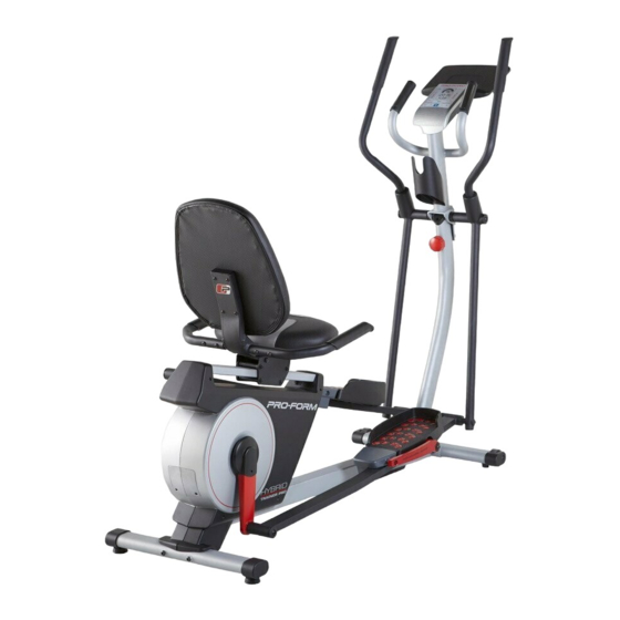
Model No. PFEL05815.1
Serial No.
USER'S MANUAL
Write the serial number in the space
above for reference.
Serial Number
Decal
CUSTOMER SERVICE
UNITED KINGDOM
Call: 0330 123 1045
From Ireland: 053 92 36102
Website: iconsupport.eu
E-mail: csuk@iconeurope.com
Write:
ICON Health & Fitness, Ltd.
Unit 4, Westgate Court
Silkwood Park
OSSETT
WF5 9TT
UNITED KINGDOM
AUSTRALIA
Call: 1800 993 770
E-mail: australiacc@iconfitness.com
Write:
ICON Health & Fitness
PO Box 635
WINSTON HILLS NSW 2153
AUSTRALIA
CAUTION
Read all precautions and
instructions in this manual before
using this equipment. Keep this
manual for future reference.
iconeurope.com
Advertisement
Table of Contents

Related Manuals for Pro-Form HYBRID TRAINER PRO


Summary of Contents for Pro-Form HYBRID TRAINER PRO
- Page 1 Model No. PFEL05815.1 Serial No. USER’S MANUAL Write the serial number in the space above for reference. Serial Number Decal CUSTOMER SERVICE UNITED KINGDOM Call: 0330 123 1045 From Ireland: 053 92 36102 Website: iconsupport.eu E-mail: csuk@iconeurope.com Write: ICON Health & Fitness, Ltd. Unit 4, Westgate Court Silkwood Park OSSETT...
-
Page 2: Table Of Contents
TABLE OF CONTENTS WARNING DECAL PLACEMENT ............. . .2 IMPORTANT PRECAUTIONS . -
Page 3: Important Precautions
IMPORTANT PRECAUTIONS WARNING: To reduce the risk of serious injury, read all important precautions and instructions in this manual and all warnings on the hybrid trainer before using the hybrid trainer. ICON assumes no responsibility for personal injury or property damage sustained by or through the use of this product. -
Page 4: Before You Begin
Thank you for selecting the revolutionary PROFORM reading this manual, please see the front cover of this ® HYBRID TRAINER PRO. The HYBRID TRAINER PRO manual. To help us assist you, note the product model provides an impressive selection of features designed number and serial number before contacting us. -
Page 5: Part Identification Chart
PART IDENTIFICATION CHART Use the drawings below to identify the small parts needed for assembly. The number in parentheses below each drawing is the key number of the part, from the PART LIST near the end of this manual. The number following the key number is the quantity needed for assembly. -
Page 6: Assembly
ASSEMBLY • Assembly requires two persons. • In addition to the included tool(s), assembly requires the following tools: • Place all parts in a cleared area and remove the one Phillips screwdriver packing materials. Do not dispose of the packing materials until you finish assembly. - Page 7 3. Orient the Upright (2) and the Front Stabilizer (5) so that the large holes (B) are facing the Upright. Attach the Front Stabilizer (5) to the Upright (2) with two M10 x 80mm Screws (19). 4. Set the Upright (2) near the Frame (1) as shown. Locate the wire tie (C) in the Frame (1) and pull the Main Wire (96) out of the underside of the Frame.
- Page 8 5. Tip: Avoid pinching the wires. Insert the Upright (2) into the Frame (1). Avoid pinching Attach the Upright (2) with six M10 x 20mm the wires Screws (76); start all the Screws, and then tighten them. Then, connect the Upper Wire (94) to the Main Wire (96).
- Page 9 7. Have a second person hold the Pivot Bracket (3) near the Upright (2). Locate the wire tie (F) in the Pivot Bracket (3). Tie the wire tie to the Upper Wire (94) and then pull the other end of the wire tie until the Upper Wire is routed through the Pivot Bracket.
- Page 10 9. Identify the Right Pedal Arm (9) and the Right Pivot Leg (8), and orient them as shown. Apply a generous amount of the included grease to the axle on the Right Pivot Leg (8). Then, slide the Right Pedal Arm (9) onto the Right Pivot Leg (8).
- Page 11 11. Remove and discard the packaging on the Right Crank Bracket (30). Then, tighten an M8 x 14mm Shoulder Screw (86) with a Pivot Cover (83) and an M8 Washer (87) into the right Crank Arm (24). Next, slide the Right Pedal Arm (9) onto the Right Crank Bracket (30).
- Page 12 13. Untie and discard the wire tie on the Upper Wire (94). While a second person holds the Console (4) near the Pivot Bracket (3), plug the Upper Wire (94) and the Left and Right Pulse Wires (103, 104) into the receptacles on the Console. The connectors on the Wires (94, 103, 104) should slide easily into the receptacles and Avoid pinching...
- Page 13 15. Identify the Right and Left Seat Handlebars (29, 93). Slide the Right Seat Handlebar (29) onto the right side of the Seat Frame (61). Attach the Right Seat Handlebar (29) with two M8 x 38mm Bolts (95) and two M8 Locknuts (68);...
- Page 14 17. Attach the Seat (28) to the Seat Frame (61) with four M6 x 20mm Screws (97) (only two are shown); start all the Screws, and then tighten them. 18. Make sure that all parts of the hybrid trainer are properly tightened. Extra parts may be included. To protect the floor or carpet from damage, place a mat under the hybrid trainer.
-
Page 15: How To Use The Hybrid Trainer
HOW TO USE THE HYBRID TRAINER HOW TO MOVE THE HYBRID TRAINER HOW TO USE THE ELLIPTICAL MODE Lift the rear stabilizer (A) until the hybrid trainer will roll To use the hybrid on the wheels. Carefully move the hybrid trainer to the trainer as an ellipti- desired location, and then lower it to the floor. - Page 16 HOW TO USE THE RECUMBENT BIKE MODE To mount the hybrid trainer in the elliptical mode, hold the handlebars (E) or the upper body arms (F) and step onto the pedal (G) that is in the lower position. To use the hybrid Then, step onto the other pedal.
- Page 17 CONSOLE DIAGRAM FEATURES OF THE CONSOLE The advanced console offers an array of features designed to make your workouts more effective and enjoyable. When you use the manual mode of the console, you can change the resistance of the pedals with the touch of a button.
- Page 18 HOW TO USE THE MANUAL MODE The upper display—This display will show your pedal- 1. Turn on the console. ing speed in revolutions per minute (RPM) and your Press any button or begin pedaling to turn on the power output in watts. The console.
- Page 19 To pause the console, stop pedaling. When the When your pulse is detected, your heart rate will be console is paused, the displays will pause. To shown in the upper display. For the most accurate continue your workout, simply resume pedaling. heart rate reading, hold the contacts for at least 15 seconds.
- Page 20 HOW TO USE A PRESET WORKOUT The speed meter will show two flashing bars 1. Turn on the console. that represent the target speed zone for the seg- Press any button or begin pedaling to turn on the ment; the target speed console.
- Page 21 THE OPTIONAL CHEST HEART RATE MONITOR 2. Connect your heart rate monitor to the console if desired. Whether your goal is to If you are connecting both your heart rate monitor and your tablet to the console, you must connect burn fat or to strengthen your your heart rate monitor before you connect...
- Page 22 HOW TO CONNECT YOUR HEART RATE MONITOR THE SETTINGS MODE TO THE CONSOLE The console features a settings mode that allows you The console is compatible with all BLUETOOTH Smart to select a unit of measurement for the console and to heart rate monitors.
-
Page 23: Maintenance And Troubleshooting
MAINTENANCE AND TROUBLESHOOTING MAINTENANCE Next, locate the Reed Switch (60). Slightly loosen, the two M4 x 19mm Screws (84). Regular maintenance is important for optimal performance and to reduce wear. Inspect and properly tighten all parts each time the hybrid trainer is used. Replace any worn parts immediately. - Page 24 HOW TO ADJUST THE DRIVE BELT Next, loosen the M10 x 55mm Bolt (99). Then, tighten the M8 Locknut (68) until the Drive Belt (64) is tight. If you can feel the pedals slip while you are pedaling, even when the resistance is adjusted to the highest level, the drive belt may need to be adjusted.
-
Page 25: Exercise Guidelines
EXERCISE GUIDELINES Burning Fat—To burn fat effectively, you must exer- WARNING: cise at a low intensity level for a sustained period of Before beginning this time. During the first few minutes of exercise, your or any exercise program, consult your physi- body uses carbohydrate calories for energy. - Page 26 SUGGESTED STRETCHES The correct form for several basic stretches is shown at the right. Move slowly as you stretch; never bounce. 1. Toe Touch Stretch Stand with your knees bent slightly and slowly bend forward from your hips. Allow your back and shoulders to relax as you reach down toward your toes as far as possible.
- Page 27 NOTES...
-
Page 28: Part List
PART LIST Model No. PFEL05815.1 R0617A Key No. Qty. Description Key No. Qty. Description Frame Crank Bearing Upright Bearing Spacer Pivot Bracket Crank Collar Console Idler Axle Front Stabilizer Idler Bolt Rear Stabilizer Idler Bushing Right Upper Body Arm Idler Bracket Right Pivot Leg Small Pulley Right Pedal Arm... - Page 29 Key No. Qty. Description Key No. Qty. Description M8 x 54mm Shoulder Screw M4 x 12mm Screw M8 x 38mm Hex Bolt Pulley Magnet Left Pulse Wire Right Pedal Brace Right Pulse Wire Left Pedal Brace M6 x 15mm Screw Pedal Brace Bushing M8 x 12mm Screw M10 x 103mm Bolt...
-
Page 30: Exploded Drawing
EXPLODED DRAWING A Model No. PFEL05815.1 R0617A... - Page 31 EXPLODED DRAWING B Model No. PFEL05815.1 R0617A...
-
Page 32: Ordering Replacement Parts
ORDERING REPLACEMENT PARTS To order replacement parts, please see the front cover of this manual. To help us assist you, be prepared to provide the following information when contacting us: • the model number and serial number of the product (see the front cover of this manual) •...