Advertisement
Table of Contents
- 1 Table of Contents
- 2 Warning Decal Placement
- 3 Important Precautions
- 4 Before You Begin
- 5 Part Identification Chart
- 6 Assembly
- 7 Pedal Leg (24) with Four M8 X 20Mm Screws
- 8 How to Use the Trainer
- 9 How to Use the Console
- 10 Fcc Information
- 11 Maintenance and Troubleshooting
- 12 Exercise Guidelines
- 13 Part List
- 14 Exploded Drawing
- 15 Ordering Replacement Parts
- 16 Limited Warranty
- Download this manual
proform.com
Model No. PFEL09920.0
Serial No.
Write the serial number in the space
above for reference.
ACTIVATE YOUR
WARRANTY
To register your product and
activate your warranty today,
go to my.proform.com.
CUSTOMER CARE
For service at any time, go to
support.proform.com.
Or call 1-888-533-1333
Mon.–Fri. 6 a.m.–6 p.m. MT
Sat. 8 a.m.–12 p.m. MT
Please do not contact the store.
CAUTION
Read all precautions and
instructions in this manual before
using this equipment. Keep this
manual for future reference.
Serial
Number
Decal
USER'S MANUAL
Advertisement
Table of Contents

Related Manuals for Pro-Form CARBON HIT H7


Summary of Contents for Pro-Form CARBON HIT H7
- Page 1 proform.com USER’S MANUAL Model No. PFEL09920.0 Serial No. Write the serial number in the space above for reference. Serial Number Decal ACTIVATE YOUR WARRANTY To register your product and activate your warranty today, go to my.proform.com. CUSTOMER CARE For service at any time, go to support.proform.com.
-
Page 2: Table Of Contents
TABLE OF CONTENTS WARNING DECAL PLACEMENT ............. . .2 IMPORTANT PRECAUTIONS . -
Page 3: Important Precautions
IMPORTANT PRECAUTIONS WARNING: To reduce the risk of serious injury, read all important precautions and instructions in this manual and all warnings on the trainer before using the trainer. ICON assumes no responsibility for personal injury or property damage sustained by or through the use of this product. - Page 4 STANDARD SERVICE PLANS...
-
Page 5: Before You Begin
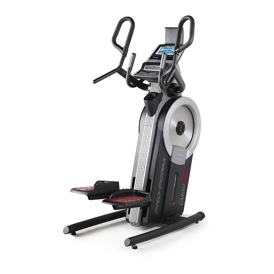
BEFORE YOU BEGIN Thank you for selecting the revolutionary PROFORM reading this manual, please see the front cover of this ® CARBON HIIT H7 trainer. The CARBON HIIT H7 manual. To help us assist you, note the product model trainer provides an impressive selection of features number and serial number before contacting us. -
Page 6: Part Identification Chart
PART IDENTIFICATION CHART Use the drawings below to identify the small parts needed for assembly. The number in parentheses below each drawing is the key number of the part, from the PART LIST near the end of this manual. The number following the key number is the quantity needed for assembly. -
Page 7: Assembly
ASSEMBLY • To hire an authorized service technician to • To identify small parts, see page 6. assemble this product, call 1-800-445-2480. • In addition to the included tool(s), assembly • Assembly requires two persons. requires the following tools: one Phillips screwdriver •... - Page 8 2. Identify the Right and Left Stabilizers (8, 9) and orient them as shown. Have a second person hold the Frame (1) and tip it to the left. IMPORTANT: Be careful not to damage the Shields (50, 51). Attach the Right Stabilizer (8) to the Frame (1) with four M10 x 20mm Screws (110);...
-
Page 9: Pedal Leg (24) With Four M8 X 20Mm Screws
4. Attach the Right Pedal Base (2) to the Right Pedal Leg (24) with four M8 x 20mm Screws (102); start all the Screws, and then tighten them. Attach the Left Pedal Base (3) to the Left Pedal Leg (25) in the same way. 5. - Page 10 6. See the upper drawing. With the help of a second person, orient the Console (5), the Console Cover (7), and the Console Bracket (4) as shown. Then, route the wires (A) on the Console through the Console Cover and the Console Bracket.
- Page 11 8. Identify the Right and Left Handlebars (10, 11). Make sure that the Pedals (22, 23) are level. Attach the Right Handlebar (10) to the Right Handlebar Arm (15) with three M8 x 25mm Screws (105); start all the Screws, and then tighten them.
- Page 12 10. Attach the Front Cover (52) to the Left and Right Shields (50, 51) with six M4 x 16mm Flat Head Screws (101); start all the Flat Head Screws, and then tighten them. 50, 51 11. Plug the Power Adapter (118) into the receptacle on the front of the trainer.
-
Page 13: How To Use The Trainer
HOW TO USE THE TRAINER HOW TO PLUG IN THE POWER ADAPTER HOW TO MOVE THE TRAINER IMPORTANT: If the trainer has been exposed to Due to the size and weight of the trainer, moving cold temperatures, allow it to warm to room tem- it requires two persons. - Page 14 HOW TO EXERCISE ON THE TRAINER HOW TO LEVEL THE TRAINER To mount the trainer, hold the handlebars (D) or the If the trainer pulse grips (E) and step onto the pedal (F) that is in the rocks slightly on lower position.
-
Page 15: How To Use The Console
HOW TO USE THE CONSOLE CONSOLE DIAGRAM FEATURES OF THE CONSOLE When you use the manual mode of the console, you can change the resistance of the pedals with the touch The advanced console offers an array of features of a button. designed to make your workouts more effective and enjoyable. - Page 16 HOW TO TURN ON THE CONSOLE HOW TO USE THE TOUCH SCREEN The included power adapter must be used to oper- The console features a tablet with a full-color touch ate the trainer. See HOW TO PLUG IN THE POWER screen.
- Page 17 HOW TO SET UP THE CONSOLE To use the manual mode, see this page. To use a featured workout or an onboard workout, see Before you use the trainer for the first time, set up the page 19. To create a draw-your-own-map work- out, see page 21.
- Page 18 4. Follow your progress. monitor, remove the plastic. To measure your heart rate, hold the handgrip heart rate monitor The console offers several display modes. The with your palms resting against the contacts. Avoid moving your hands or gripping the contacts display mode that you select will determine which tightly.
- Page 19 HOW TO USE A FEATURED WORKOUT OR AN To draw your own map for a workout, see HOW TO ONBOARD WORKOUT CREATE A DRAW-YOUR-OWN-MAP WORKOUT on page 21. 1. Touch the screen or press any button on the console to turn on the console. When you select a workout, the screen will show an overview of the workout that includes details See HOW TO TURN ON THE CONSOLE on...
- Page 20 If the resistance level is too high or too low, you When the workout ends, a workout summary will can manually override the setting by pressing the appear on the screen. If desired, you can select Resistance buttons. If you press a Resistance options such as adding the workout to your sched- button, you can then manually control the resis- ule (see HOW TO USE AN IFIT WORKOUT on...
- Page 21 HOW TO CREATE A DRAW-YOUR-OWN-MAP If you make a mistake, touch Undo in the map WORKOUT options. 1. Touch the screen or press any button on the The screen will display the elevation and distance console to turn on the console. statistics for your workout.
- Page 22 HOW TO USE AN IFIT WORKOUT 4. Select an iFit workout that you have previously added to your schedule on iFit.com. To use an iFit workout, the console must be connected IMPORTANT: Before iFit workouts will load, you to a wireless network (see HOW TO CONNECT TO A must add them to your schedule on iFit.com WIRELESS NETWORK on page 24).
- Page 23 HOW TO CHANGE CONSOLE SETTINGS 3. Customize the unit of measurement and other settings. IMPORTANT: Some of the settings and features described may not be enabled. Occasionally, a To customize the unit of measurement, the time firmware update may cause your console to function zone, or other settings, touch Equipment Info or slightly differently.
- Page 24 HOW TO CONNECT TO A WIRELESS NETWORK Note: You must have your own wireless network and an 802.11b/g/n router with SSID broadcast To use iFit workouts and to use several other features enabled (hidden networks are not supported). of the console, the console must be connected to a wireless network.
- Page 25 HOW TO USE THE SOUND SYSTEM When your device and the console pair successfully, the audio from your device will play through the con- To play music or audio books through the console sole sound system. sound system while you exercise, plug a 3.5 mm male to 3.5 mm male audio cable (not included) into the The console can save 8 devices in its memory.
-
Page 26: Fcc Information
FCC INFORMATION This equipment has been tested and found to comply with the limits for a Class B digital device, pursuant to part 15 of the FCC Rules. These limits are designed to provide reasonable protection against harmful interference in a residential installation. This equipment generates, uses, and can radiate radio frequency energy and, if not installed and used in accordance with the instructions, may cause harmful interference to radio communications. -
Page 27: Maintenance And Troubleshooting
MAINTENANCE AND TROUBLESHOOTING MAINTENANCE PEDAL TROUBLESHOOTING Regular maintenance is important for optimal If the pedals bottom out while you are exercising and performance and to reduce wear. Inspect and properly become difficult to move, rock your weight backward tighten all parts each time the trainer is used. Replace and forward on the pedals until the pedals become free any worn parts immediately. - Page 28 HOW TO ADJUST THE DRIVE BELT Stand on the trainer and pedal for a few moments. If the pedals still slip, step off the trainer and locate If the pedals slip while you are pedaling, even while the upper Adjustment Screw (B). Tighten the upper the resistance is adjusted to the highest level, the drive Adjustment Screw two turns;...
-
Page 29: Exercise Guidelines
EXERCISE GUIDELINES Burning Fat—To burn fat effectively, you must exer- WARNING: cise at a low intensity level for a sustained period of Before beginning this time. During the first few minutes of exercise, your or any exercise program, consult your physi- body uses carbohydrate calories for energy. - Page 30 SUGGESTED STRETCHES The correct form for several basic stretches is shown at the right. Move slowly as you stretch; never bounce. 1. Toe Touch Stretch Stand with your knees bent slightly and slowly bend forward from your hips. Allow your back and shoulders to relax as you reach down toward your toes as far as possible.
- Page 31 NOTES...
-
Page 32: Part List
PART LIST Model No. PFEL09920.0 R1219A Key No. Qty. Description Key No. Qty. Description Frame Right Shield Right Pedal Base Front Cover Left Pedal Base Rear Cover Console Bracket Accessory Tray Base Console Stabilizer Cap Snap Ring Foot Console Cover Wheel Right Stabilizer Right Wheel Cover... - Page 33 Key No. Qty. Description Key No. Qty. Description M4 x 16mm Flat Head Screw M10 Screw M8 x 20mm Screw M4 x 19mm Screw Cap Screw M4 x 12mm Screw Pulley Magnet Main Wire M8 x 25mm Screw Reed Switch/Wire M4 x 16mm Screw Pulse Wire M4 x 22mm Screw...
-
Page 34: Exploded Drawing
EXPLODED DRAWING A Model No. PFEL09920.0 R1219A... - Page 35 EXPLODED DRAWING B Model No. PFEL09920.0 R1219A...
-
Page 36: Ordering Replacement Parts
ORDERING REPLACEMENT PARTS To order replacement parts, please see the front cover of this manual. To help us assist you, be prepared to provide the following information when contacting us: • the model number and serial number of the product (see the front cover of this manual) •...