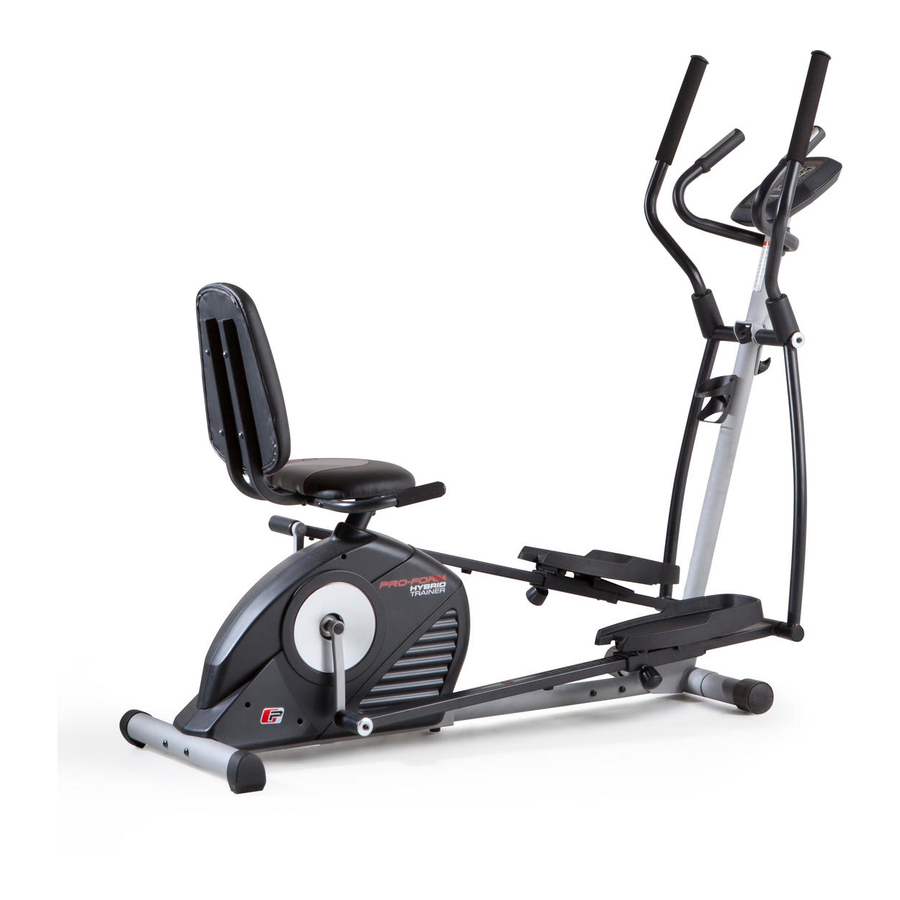
Pro-Form HYBRID TRAINER User Manual
Hide thumbs
Also See for HYBRID TRAINER:
- User manual (28 pages) ,
- User manual (29 pages) ,
- User manual (32 pages)
Table of Contents
Advertisement
Quick Links
www.proform.com
USER'S MANUAL
Model No. PFEL05814.0
Serial No.
Write the serial number in the space
above for reference.
Serial Number
Decal
ACTIVATE YOUR
WARRANTY
To register your product and
activate your warranty today,
go to www.proformservice.com/
registration.
CUSTOMER CARE
For service at any time, go to
www.proformservice.com.
Or call 1-888-533-1333
Mon.–Fri. 6 a.m.–6 p.m. MT
Sat. 8 a.m.–12 p.m. MT
Please do not contact the store.
CAUTION
Read all precautions and instruc-
tions in this manual before using
this equipment. Keep this manual
for future reference.
Advertisement
Table of Contents

Related Manuals for Pro-Form HYBRID TRAINER


Summary of Contents for Pro-Form HYBRID TRAINER
- Page 1 www.proform.com USER’S MANUAL Model No. PFEL05814.0 Serial No. Write the serial number in the space above for reference. Serial Number Decal ACTIVATE YOUR WARRANTY To register your product and activate your warranty today, go to www.proformservice.com/ registration. CUSTOMER CARE For service at any time, go to www.proformservice.com.
-
Page 2: Table Of Contents
HOW TO USE THE HYBRID TRAINER ........ -
Page 3: Important Precautions
To reduce the risk of serious injury, read all important precautions and instructions in this manual and all warnings on your hybrid trainer before using your hybrid trainer. ICON assumes no responsibility for personal injury or property damage sustained by or through the use of this product. - Page 4 STANDARD SERVICE PLANS...
-
Page 5: Before You Begin
For your benefit, read this manual carefully before Before reading further, please familiarize yourself with you use the hybrid trainer. If you have questions after the parts that are labeled in the drawing below. reading this manual, please see the front cover of this... -
Page 6: Part Identification Chart
PART IDENTIFICATION CHART Use the drawings below to identify the small parts needed for assembly. The number in parentheses below each drawing is the key number of the part, from the PART LIST near the end of this manual. The number following the key number is the quantity needed for assembly. -
Page 7: Assembly
ASSEMBLY • To hire an authorized service technician to • To identify small parts, see page 6. assemble the hybrid trainer, call 1-800-445-2480. • In addition to the included tool(s), assembly • Assembly requires two persons. requires the following tools: one Phillips screwdriver •... - Page 8 3. Orient the Front Stabilizer (2) so that the large holes are facing the Front Frame (23). Attach the Front Stabilizer to the Front Frame with two M10 x 65mm Screws (40). Large Holes 4. Set the Front Frame (23) near the Rear Frame (1) as shown.
- Page 9 5. Tip: Avoid pinching the wires. Slide the Front Frame (23) onto the Rear Frame (1). Avoid pinching Attach the Front Frame (23) with an the wires M10 x 25mm Screw (96), an M10 Split Washer (98), and an M10 Curved Washer (39). Do not tighten the Screw yet.
- Page 10 7. Tip: Avoid pinching the Upper Wire (105). Slide the Console Post (73) onto the Front Frame (23) and hold it in place. Next, insert the Axle (80) into the Console Post (73) and into the Front Frame (23). Center the Axle.
- Page 11 Washer (81), and the Right Pedal Leg (71) onto the axle. Then, tighten an M8 x 20mm Screw (34), a Pivot Cover (90), and an M8 Large Washer (54) into the axle. Repeat this step on the other side of the hybrid trainer. Grease...
- Page 12 Washers (42). Start all three Screws, and then tighten them. Repeat this step on the other side of the hybrid trainer. 12. Have a second person hold the Handlebar (53) near the Console Post (73). Insert the indicated wire tie into the hole in the...
- Page 13 If you do not connect the connectors properly, the console may become damaged when you use the hybrid trainer. Avoid pinching Insert the excess wire into the Console Post (73) the wires or into the Console (16).
- Page 14 15. Identify the Right Upper Body Arm (88). Orient an Upper Body Arm Cover (82) as shown, and slide it upward onto the Right Upper Body Arm (88). Attach the Right Upper Body Arm (88) to the Right Upper Body Leg (86) with three M8 x 40mm Bolts (83) and three M8 Locknuts (10);...
- Page 15 17. Attach the Left and Right Seat Brackets (14, 15) to the Rear Frame (1) with two M8 x 125mm Bolts (58), four M8 Small Washers (93), and two M8 Locknuts (10). 18. IMPORTANT: If you purchased the optional iFit module, insert the iFit module into the iFit port on the Console (16) before you attach the Tablet Holder (101).
- Page 16 HOW TO PLUG IN THE POWER ADAPTER on page 17. 20. Make sure that all parts of the hybrid trainer are properly tightened. Note: Extra parts may be included. To protect the floor or carpet from damage, place a mat under the hybrid trainer.
-
Page 17: How To Use The Hybrid Trainer
HOW TO MOVE THE HYBRID TRAINER IMPORTANT: If the hybrid trainer has been exposed Due to the size and weight of the hybrid trainer, to cold temperatures, allow it to warm to room moving it requires two persons. Stand in front of the temperature before you plug in the power adapter. - Page 18 HOW TO USE THE ELLIPTICAL MODE Each pedal can be adjusted to several positions. To To use the hybrid trainer as an elliptical, first pivot the adjust the position of each pedal, loosen the pedal console post to the high position and tighten the con- knob, move the pedal forward or backward to the sole knob and the washer into the front frame.
- Page 19 HOW TO USE THE RECUMBENT BIKE MODE To mount the hybrid trainer in the elliptical mode, hold the handlebars or the upper body arms and step onto the pedal that is in the lower position. Then, step onto To use the hybrid trainer as a recumbent bike, first the other pedal.
- Page 20 CONSOLE DIAGRAM MAKE YOUR FITNESS GOALS A REALITY WITH Upload your workout results to the iFit cloud IFIT.COM and track your accomplishments. With your new iFit-compatible fitness equipment, you can use an array of features on iFit.com to make your Set calorie, time, or distance goals for your fitness goals a reality: workouts.
- Page 21 FEATURES OF THE CONSOLE HOW TO USE THE MANUAL MODE The advanced console offers an array of features 1. Begin pedaling or press any button on the console to turn on the console. designed to make your workouts more effective and enjoyable.
- Page 22 Calories (Cals.)—This display mode will show the As you exercise, the workout intensity level bar approximate number of calories you have burned. will indicate the approximate intensity level of your exercise. Calories per Hour (Cals./Hr)—This display mode will show the approximate number of calories you are burning per hour.
- Page 23 Note: The console features a display demo mode, mance, clean the contacts using a soft cloth; never designed to be used if the hybrid trainer is dis- use alcohol, abrasives, or chemicals to clean played in a store. When the demo mode is turned the contacts.
- Page 24 HOW TO USE AN ONBOARD WORKOUT At the end of each segment of the workout, a series of tones will sound and the next segment of 1. Begin pedaling or press any button on the the profile will begin to flash. If a different resis- console to turn on the console.
- Page 25 HOW TO USE A SET-A-GOAL WORKOUT Note: The calorie goal is an estimate of the number of calories that you will burn during 1. Begin pedaling or press any button on the the workout. The actual number of calories that console to turn on the console.
- Page 26 HOW TO USE AN IFIT WORKOUT Press the Map button, the Train button, or the Lose Wt. button to download the next workout of that You must have an iFit module to use an iFit workout. type in your schedule. To purchase an iFit module at any time, go to www.iFit.com or call the telephone number on the Press the Compete button to compete in a race...
- Page 27 6. Follow your progress with the display. HOW TO USE THE SOUND SYSTEM See step 4 on page 21. To play music or audio books through the console sound system while you exercise, plug a 3.5 mm male The My Trail tab will show a map of the trail or it will to 3.5 mm male audio cable (not included) into the jack show a track and the number of laps you complete.
- Page 28 HOW TO CHANGE CONSOLE SETTINGS Demo—The console features a display demo mode, designed to be used if the hybrid trainer is 1. Select the settings mode. displayed in a store. Press the Enter button repeat- edly to turn the demo mode ON or OFF.
-
Page 29: Maintenance And Troubleshooting
Next, locate the Reed Switch (43). Loosen, but do not remove, the M4 x 12mm Screw (31). To clean the hybrid trainer, use a damp cloth and a small amount of mild soap. IMPORTANT: To avoid damage to the console, keep liquids away from the console and keep the console out of direct sunlight. -
Page 30: Fcc Information
HOW TO ADJUST THE DRIVE BELT If you can feel the pedals slip while you are pedaling, even when the resistance is adjusted to the highest level, the drive belt may need to be adjusted. To adjust the drive belt, see EXPLODED DRAWING A on page 34. -
Page 31: Exercise Guidelines
EXERCISE GUIDELINES Burning Fat—To burn fat effectively, you must exer- WARNING: cise at a low intensity level for a sustained period of Before beginning this time. During the first few minutes of exercise, your or any exercise program, consult your physi- body uses carbohydrate calories for energy. -
Page 32: Part List
PART LIST Model No. PFEL05814.0 R1214A Key No. Qty. Description Key No. Qty. Description Rear Frame M6 x 20mm Hex Screw Front Stabilizer M4 x 16mm Screw Upper Body Arm Cap M10 Locknut Wheel M6 x 30mm Bolt Snap Ring Upper Body Arm Grip Rear Stabilizer M6 Locknut... - Page 33 Key No. Qty. Description Key No. Qty. Description Ground Screw Power Receptacle/Wire M4 x 10mm Screw Power Adapter M8 Small Washer Tablet Holder M8 x 65mm Bolt #8 x 12mm Screw M8 x 13mm Screw Power Bracket M10 x 25mm Screw Crank Arm Bushing M10 x 54mm Screw Upper Wire...
-
Page 34: Exploded Drawing
EXPLODED DRAWING A Model No. PFEL05814.0 R1214A... - Page 35 EXPLODED DRAWING B Model No. PFEL05814.0 R1214A...
-
Page 36: Ordering Replacement Parts
ORDERING REPLACEMENT PARTS To order replacement parts, please see the front cover of this manual. To help us assist you, be prepared to provide the following information when contacting us: • the model number and serial number of the product (see the front cover of this manual) •...