Advertisement
Quick Links
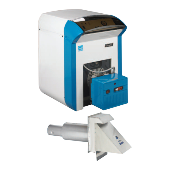
EUTECTIC
DIRECT VENT OIL-FIRED WATER BOILER/NO. 2 OIL
CONTENTS . . . . . . . . . . . . . . . . . . . . . . . . . . . . . . . . . . . . . . . . . .PAGE
Basic Guidelines . . . . . . . . . . . . . . . . . . . . . . . . . . . . . . . . . . . . . . . . . .1
Application
Typical Installation . . . . . . . . . . . . . . . . . . . . . . . . . . . . . . . . . . . . . . .2
Vent Kit Description & Warnings . . . . . . . . . . . . . . . . . . . . . . . . . . . . . .3
Outside Terminal
Installing the outside terminal . . . . . . . . . . . . . . . . . . . . . . . . . . . . . .4
Connections to the outside terminal . . . . . . . . . . . . . . . . . . . . . . . . .5
Connections to appliance . . . . . . . . . . . . . . . . . . . . . . . . . . . . . . . . . . .5
Maintenance . . . . . . . . . . . . . . . . . . . . . . . . . . . . . . . . . . . . . . . . . . . . .5
Appliance adapter assembly . . . . . . . . . . . . . . . . . . . . . . . . . . . . . . . . .6
Joint assembly . . . . . . . . . . . . . . . . . . . . . . . . . . . . . . . . . . . . . . . . . . . .6
Connection of vacuum relief valve . . . . . . . . . . . . . . . . . . . . . . . . . . . . .7
Slant/Fin EC-10DV SERIES, models DV are approved for installation
as a direct vent system. The following basic guidelines should be
observed according to the venting system in use. In addition, it is
strongly recommended that the applicable precautions for Natural
Draft Applications be used.
DO NOT DESTROY
THESE INSTRUCTIONS MUST
REM IN WITH EQUIPMENT
In addition to all the pertinent information regarding Natural
Draft Applications whenever a Mechanical Draft Application is
used it should be installed using the following instructions and
Figures 2 and 3 (on pages 4 and 5) as reference.
•
The terminating vent hood, and the inlet air hood are on
the same wall surface. and are on the wall opposite from
the prevailing wind wall.
•
All of the air for combustion to the burner is supplied
directly from the outside of the building or structure.
•
Not less than 305 mm (12 in.) above the total accumulated
snow and level grade.
•
Not less than 1219 mm (4 ft.) horizontally or below any
window, and door or air inlet and also not less than
305 mm (1 ft.) above any of these openings.
•
Not less than 914 mm (3 ft.) above a powered air inlet
device that is within 3048 mm (10 ft.).
•
Not less than 609 mm (2 ft.) from any other building.
EC-10DV Series
VENTING INSTALLATION INSTRUCTIONS
Installation Considerations
•
At least 914 mm (3 ft.) from any inside corner of a building
•
At least 305 mm (1 ft.) from any roof soffit or ridge vent.
•
At least 2134 mm (7 ft.) above any public walkway.
•
All of the vent construction consists of approved materials,
and terminates at an approved stainless steel hood.
•
All of the vent piping must be sealed from air leaks.
•
The vent pipe bend radius is 305 mm (12 in.)
•
Brace metal strapping every 914 mm (36 in.) to support
vent pipe and prevent it from sagging.
•
Follow the national codes for the installation of oil burning
equipment in USA-NFPA 31, in Canada CAN/CSA - B139
and local regulations.
PUBLICATION NO. ECDV40-V RevA
Printed in U.S.A. 1113
Part No. 470912000
Advertisement

Related Manuals for Slant/Fin EUTECTIC 10 Series


Summary of Contents for Slant/Fin EUTECTIC 10 Series
- Page 1 Connection of vacuum relief valve ......7 Slant/Fin EC-10DV SERIES, models DV are approved for installation as a direct vent system.
- Page 2 Moisture and ice may form around terminal. Make sure the surface is in good repair and protected from damage. Only Slant/Fin models EC10DV boilers can be installed on sealed or direct vented systems. They must be ordered from the factory with an approved Direct Vent System.
- Page 3 EC10DV SERIES ITEMS INCLUDED IN KIT: FIELD DIRECT VENT SYSTEM FDVS Direct Vent Termination VRV-4 Vacuum Relief Valve Backing Plate Installation Instruction Sheet **Bagged Hardware **Cover Ring **Cover Sleeve **Appliance Adapter **Adapter Clamp **Included with FOVP (Flex Oil Vent Pipe) for some models Model: FDVS The Field Direct Vent System (FDVS) is a non-powered positive pressure side wall vent termination system for use only with specifically listed oil fired appliances.
- Page 4 EC10DV SERIES INSTALLATION OF FDVS DIRECT VENT SYSTEM Installation of the Vent Termination 1. Remove vent system components from box and inspect for damage. If the carton has been crushed or mutilated, check components very carefully for damage. DO NOT install if any damage is apparent.
-
Page 5: Maintenance
EC10DV SERIES INSTALLATION OF THE VENT TERMINATION CONNECTING THE COMBUSTION AIR INTAKE PIPE FROM COMBUSTION AIR TEE THE FDVS TO THE APPLIANCE 1. Assemble the combustion air tee assembly body to the vent 1. Use 4" galvanized steel pipe or stainless steel pipe from the termination outer pipe, and rotate to the desired position. - Page 6 EC10DV SERIES APPLIANCE ADAPTER INSTALLATION: 1. Apply a bead of sealant to appliance collar approx. 1” from end of collar (Figure 5). 2. Remove all oil and grease from the inside of the appliance adapter, and apply a bead of sealant to inside of adapter ?” from end (Figure 5).
- Page 7 EC10DV SERIES FIGURE 11: Connection of vacuum relief valve FIGURE 12: Vacuum relief valve...
- Page 8 SLANT/FIN CORPORATION, Greenvale, N.Y. 11548 • Phone: (516) 484-2600 Canada: Slant/Fin Mississauga, Ontario FAX: (516) 484-5921 • LTD/LTEE, www.slantfin.com...