IDEAL mini C28 Installation And Servicing
Hide thumbs
Also See for mini C28:
- User manual (4 pages) ,
- User manual (4 pages) ,
- Installation and servicing (60 pages)
Advertisement
Quick Links
installation and
servicing
mini
Your Ideal installation and servicing guide
C24/C28/C32
S24/S28
When replacing any part of this appliance, use only spare parts that you can be
assured conform to safety and performance specification that we require. Do not use
reconditioned or copy parts that have not been clearly authorised by Ideal Boilers
Advertisement

Related Manuals for IDEAL mini C28


Summary of Contents for IDEAL mini C28
- Page 1 When replacing any part of this appliance, use only spare parts that you can be assured conform to safety and performance specification that we require. Do not use reconditioned or copy parts that have not been clearly authorised by Ideal Boilers...
- Page 2 GENERAL Table 1 --- Boiler Data Mini C24 Mini C28 Mini C32 Mini S24 Mini S28 Gas supply type & connection G20 20mbar, G31 37mbar, 22 mm copper 2H3P Inlet / Outlet connection --- Domestic Hot Water 15 mm copper Flow &...
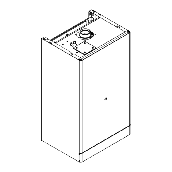
- Page 3 GENERAL Mini CONTENTS Mini C24 G.C. appliance No. 47 ---348 ---18 Air supply Mini C28 G.C. appliance No. 47 ---348 ---19 Boiler clearances Mini C32 G.C. appliance No. 47 ---348 ---25A Mini S24 G.C. appliance No. 41 ---392 ---98 Boiler exploded view Mini S28 G.C.
- Page 4 GENERAL BOILER WATER CONNECTION Pipe size O.D. mm CH flow Wall mounting CH return plate Gas inlet DHW cold inlet * DHW hot outlet * 20 (3/4”) * Pipe connections not used on system boilers 255 (10”) 85 (3 5/16”) BOILER CLEARANCES (17 3/4”) overall clearance is still required, with the cupboard door open, to allow for servicing.
- Page 5 INTRODUCTION GAS SAFETY Current Gas Safety (Installation and Use) Mini C24, Mini C28 and Mini C32 are wall mounted, low water content, balanced flue combination gas boilers. Regulations or rules in force Mini S24 and Mini S28 are wall mounted, low water content, The appliance is suitable only for installation in GB and IE and balanced flue system gas boilers.
- Page 6 GENERAL LOCATION OF BOILER AND FLUE OUTLET The boiler is adjusted at the factory for use with the relevant supply gas. A working gas pressure equal to that stated in Table 1 MUST be available at the boiler inlet. The boiler must be installed on a flat and vertical wall, capable of adequately supporting the weight of the boiler and any Where applicable, the appliance can be converted for ancillary equipment.
- Page 7 Treatment in Central Heating Systems. practice, that products of combustion discharging from the Caradon Ideal Limited recommend the use of Fernox, GE terminal cannot re ---enter the building or any other adjacent Betz Sentinel or Salamander water treatment products, which...
- Page 8 F Re ---pressurise the system to the desired charge pressure (see Table 5). 2 Flow Temperature The installation should be designed to work with flow Table 5 Mini C24, Mini S24, Mini C28, Mini S28 temperatures of up to 90 ° C. System charge pressure 3 Working Pressure...
- Page 9 2 For the minimum and maximum working pressures of the b. Hot and cold supplies are of equal pressure. Mini C24, Mini C28 and Mini C32 domestic hot water circuit refer to Table 1, page 2. 6 Hard water areas 3 The cold water supply pipe should be flushed before In areas where the water is ’hard’...
- Page 10 BOILER WATER CIRCUIT DIAGRAM 1 Domestic hot water (DHW) heat exchanger 2 Domestic hot water (DHW) flow switch Mini C24 --- Mini C28 --- Mini C32 3 Domestic hot water (DHW) outlet pipe 4 Domestic cold water inlet cock 5 Three ---way diverter valve...
- Page 11 34 Burner 11 Main circuit drainage cock 23 Model identification & instructions 35 Air pressure switch 12 Auto air vent 24 Control panel door 36 Expansion vessel * Mini C24, Mini C28 and Mini C32 only Mini Installation & Servicing...
- Page 12 F Pre ---piping frame F 1/2” DHW cold inlet isolating valve --- 1 off. * F Natural gas to LPG conversion kit * Mini C24, Mini C28 and Mini C32 only F LPG to natural gas conversion kit PACKAGING To unpack the boiler refer to the instructions on carton end flap.
- Page 13 INSTALLATION FITTING THE FLUE SYSTEM Table 9 --- Models Mini C24, Mini S24, Mini C28, Mini S28 Pipe length (ø 80/125) Restrictor The maximum total equivalent lengths are given in Table 7 and Table 8 for co---axial pipes ø 60 ---100 mm, Between 0,5 (19.5“) and 1,5 m (59“)
- Page 14 INSTALLATION FITTING THE FLUE SYSTEM (cont.) Twin pipe flue kits For calculation of total flue length, the distance MUST be Co---axial Flue kits. measured from the centreline of the flue duct/air duct connection to the end of the flue outlet grille/air inlet duct. Horizontal.
- Page 15 INSTALLATION WALL MOUNTING TEMPLATE (rear flue) IMPORTANT Detailed installation steps are given directly on the wall mounting template 1 Tape the template into the selected position. 2 Ensure squareness by hanging a plumbine. 3 Mark onto the wall the following: a.
- Page 16 Gas inlet Domestic cold water inlet * Central Heating return * Mini C24, Mini C28 and Mini C32 only Connect to the tail pipes by proprietory fittings. The pipework may be directed down or through the rear wall as required.
- Page 17 Mains wiring should be 3 core PVC insulated flexible cord NOT LESS than 0.75 mm (24 x 0.2mm) and to BS. 6500, Mini C24, Mini C28 Mini C32 only Table 16. (0.5mm flex is not acceptable --- for mechanical, For external controls wiring see frame 26.
- Page 18 INSTALLATION PICTORIAL WIRING Mini C24, Mini C28, Mini C32 Wiring diagram for boiler equiped with full sequence ignition device type: Bertelli & Partners FM30 External controls Electric supply Safety Air pressure Ignition Flame detection terminal block terminal block thermostat switch...
- Page 19 INSTALLATION Wiring diagram for boiler equiped with full sequence ignition device type: Honeywell FPLD External controls Electric supply Safety Air pressure Ignition Flame detection terminal block terminal block thermostat switch electrodes electrode gnye gnye Electronic control p.c.b. Full sequence bn = brown ignition device P .C.B.
- Page 20 INSTALLATION PICTORIAL WIRING Mini S24, Mini S28 Wiring diagram for boiler equiped with full sequence ignition device type: Bertelli & Partners FM30 Electric supply Safety Air pressure Ignition Flame detection terminal block thermostat switch electrodes electrode gnye gnye Electronic control p.c.b. Full sequence bn = brown ignition device...
- Page 21 INSTALLATION Wiring diagram for boiler equiped with full sequence ignition device type: Honeywell FPLD Electric supply Safety Air pressure Ignition Flame detection terminal block thermostat switch electrodes electrode gnye gnye Electronic control p.c.b. Full sequence bn = brown ignition device P .C.B.
- Page 22 INSTALLATION FUNCTIONAL FLOW DIAGRAM Mini C24, Mini C28, Mini C32 Detection Ignition P .C.B. #1 P .C.B. #2 electrode electrodes Pump Programmer Room thermostat CH temp. probe Main Ignition pcb Air pressure switch DHW temp. probe control pcb Three way div.
- Page 23 External controls Optional Programmer Kit terminal block For the models Mini C24, Mini C28 and Mini C32 (combi) an optional digital programmer kit is available with its relevant instructions. Note: the switch contacts of any external programmer, External programmer room or frost thermostat must be volt free.
- Page 24 Switched 3 Amp fused, spur Do not remove Mid--- position diverter valve INITIAL LIGHTING Mini C24 Mini C28 Mini C32 Mini S24 Mini S28 Legend Central Heating flow A Appiance On lamp Domestic hot B Domestic hot water temperature control...
- Page 25 INSTALLATION 7 Switch the electricity supply ON and check that all 11 Operate the boiler for 10 minutes to stabilise the burner external controls are calling for heat. temperature. 8 Set the main switch C to ’ON’. Following a pre ---purge 12 Check that the burner pressures are correct.
- Page 26 Make the following checks for correct operation: 10.5 (4.2) mbar (in. w.g.) for the model Mini C32. 1 Hot water (Mini C24, Mini C28 and Mini C32 models). 4 Water circulation system a. Fully open all DHW taps in turn and ensure that water flows Note.
- Page 27 INSTALLATION GAS CONVERSION 6 Adjust the burner pressures according to the indications given in frame 29. 1 Disconnect the electrical supply. 7 Stick on the inside of the left hand side panel adjacent to 2 Replace the burner injectors as explained in frame 45. the data badge the self ---adhesive label (included with the 3 Re ---assemble the burner, the front panel of the conversion kit) indicating the type of gas, and the gas...
- Page 28 SERVICING SERVICING SCHEDULE Note. If your meter reads CO in parts per million the figure must be divided by 10,000 to convert it to a percentage. To ensure the continued safe and efficient operation of the 5 If the ratio of CO/CO is less than ,004 and the gas rates appliance it is recommended that it is checked at regular measured in steps 3 and 4 are close to nominal then no...
- Page 29 SERVICING REMOVAL OF OUTER AND INNER 5 Remove the screws C and remove the boiler inner casing. CASING 1 Turn off the gas supply at the gas service cock and disconnect the electricity supply. 2 Remove the screws A and lift off the boiler front panel. 3 Loosen the screws B.
- Page 30 Burner blade Ignition Male Detection Female Mini C24, Mini C28, Mini S24, Mini S28 Burner blades 4 Disconnect the electrodes leads. 4 mm (5/32”) 5 Undo the four screws C placed at the right and left sides of the burner and extract it.
- Page 31 SERVICING RE ---ASSEMBLY 6 Refit the inner case cover. IMPORTANT. Ensure the boiler sealing panel is correctly fitted and that a good seal is made. Re ---assemble the boiler in the following order: 3 Refit the burner. 7 Refit the boiler side and front panels. 4 Reconnect the electrodes to the ignition pcb.
- Page 32 4 Remove the burner. Refer to frame 37. 5 Undo the screws that hold the electrodes and remove. Detection 6 For models Mini C24, Mini C28, Mini S24, Mini S28, fit new electrodes as necessary following the sequence illustrated. 10 mm (3/8”)
- Page 33 1 Remove outer and inner casing (refer to frame 36). For models Mini C28, Mini S28 and Mini C32 remove the screw A and the plate B. 4 Re ---assemble in reverse order.
- Page 34 SERVICING THERMISTOR REPLACEMENT 1 Disconnect the electrical supply. 2 Remove the front and right hand side casing panels (refer to frame 36). DHW thermistor 3 Close off the isolating cocks of the CH circuit at the bottom of the boiler. 4 Release system pressure by opening the main circuit drainage cock.
- Page 35 SERVICING GAS VALVE REPLACEMENT 1 Turn off the gas supply at the gas service cock and disconnect the electricity supply. 2 Remove the front casing panel (refer to frame 36). 3 Disconnect the connectors A and B. 4 Disconnect the earth wiring from the gas valve. 5 Unscrew the connectors C and remove the pipe D 6 Unscrew the inlet connector.
- Page 36 SERVICING FAN REPLACEMENT If the right clearance is at least 50 cm (20”)..6 Unscrew the 3 screws E and remove the fan. 1 Disconnect the electrical supply. 2 Remove outer and inner casing. 3 Disconnect the connectors A and the earth connection B. 7 Re ---assemble in reverse order.
- Page 37 SERVICING AIR PRESSURE SWITCH REPLACEMENT Two different types of air pressure switch may be used in the boiler. Refer tho the following drawings in accordance with the type of air pressure switch used. 1 Disconnect the electrical supply. 2 Remove outer and inner casing as explained in frame 36. 3 Disconnect the pressure sensing pipe from the air pressure switch.
- Page 38 Refer to the illustration 1 for the position of the jumpers when 4 To gain access to the main control p.c.b. and the ignition the main control p.c.b. is fitted on a Mini C24, Mini C28 or p.c.b. remove the screws B and remove the control panel Mini C32 boiler.
- Page 39 SERVICING IGNITION PCB REPLACEMENT 1 Gain access to the parts located inside the control panel as explained in the the frame 56. 2 Remove all the wiring connected to the ignition p.c.b. To disconnect the connectors indicated, delicately flex the hook present on one side of each socket.
- Page 40 The Mini C24 model is factory fitted with a 10 litre/min. flow limiter. Spring seat D --- body The Mini C28 model is factory fitted with a 12 litre/min. flow limiter. C --- filter Spring The Mini C32 model is factory fitted with a 14 litre/min. flow limiter.
- Page 41 5 Remove the combustion chamber panel A by unscrewing the screws B. For models Mini C28, Mini S28 and Mini C32 only, remove the screw C and the plate D. 6 Remove the clips E and the safety thermostat F. It is not necessary to disconnect it from the wiring.
- Page 42 SERVICING DHW HEAT EXCHANGER 8 Completely unscrew the two Allen key screws C which hold the exchanger to the brass groups. REPLACEMENT Mini C only 1 Disconnect the electrical supply. 2 Remove outer casing (refer to frame 36). 3 Close the isolating cocks of the CH circuit and DHW supply at the bottom of the boiler.
- Page 43 SERVICING DIVERTER VALVE INTERNAL PARTS REPLACEMENT Mini C only 1 Disconnect the electrical supply. 2 Remove front and left hand casing panels (refer to frame 36). 3 Close the isolating cocks of the CH circuit and DHW supply at the bottom of the boiler. 4 Release system pressure by opening the main circuit drainage cock.
- Page 44 SERVICING PROGRAMMER REPLACEMENT 4 Squeeze the hooks that hold the programmer on the control panel fascia and withdraw the faulty programmer. (if fitted) 5 Re ---assemble in reverse order. 1 Disconnect the electrical supply. When reassembling the new programmer, refer to the wiring diagram in frame 22 for the correct wiring connection.
- Page 45 SERVICING Mini Installation & Servicing...
- Page 46 FAULT FINDING MAIN CONTROL P .C.B. OPTICAL INFORMATION The main control p.c.b. is provided with three lamps (L.E.D. indicators) A that give optical information during the normal operation of the boiler or for service and fault fiinding purpose. Normal operation Only the green lamp on the left is directly visible on the control panel fascia and it gives information during the normal operation of the boiler.
- Page 47 FAULT FINDING FAULT FINDING With a fast pulse showing on LED 1 the boiler will continue to operate with a reduced performance in some fault conditions. WARNING Care must be taken when conducting fault finding tests to Before commencing fault finding please check the following: guard against the risk of electric shock.
- Page 48 FAULT FINDING Continued from page 47 of fault finding With the boiler and Is there between Is the continuity of the Repair or replace heating circuit warm 0Vdc and 16Vdc at modulator harness faulty wiring does the burner the grey and black O.K? pressure reduce if the connections on the...
- Page 49 FAULT FINDING Continued from page 47 of fault finding. Is the green LED on front fascia flashing 4 times per second? Are LED 2 and LED 3 Is LED 2 flashing and Continued on page Access the 4 dip flashing? LED 3 on? 50 of fault finding switches on p.c.b.
- Page 50 FAULT FINDING Are LED 1 and LED 3 Continued on Continued from page 49 flashing with LED 2 page 52 of of fault finding on, plus LED 4 on the fault finding facia on? Is there >17mbar at Rectify gas supply the gas valve inlet? fault.
- Page 51 FAULT FINDING Continued from page 50 of fault finding Does the burner Rectify electrode Is the position of the remain alight? position or replace detection electrode correct, faulty electrode. and electrode undamaged? Refer to frame 43. Is the lead Connect lead Is the resistance of the connected? correctly.
- Page 52 FAULT FINDING Continued from Is LED 1 on and LED Is LED 1 flashing and page 50 of fault 2 flashing? LED 2 and LED 3 on? finding Is dip---switch # 3 in Replace faulty PCB # Is dip---switch # 3 in Replace faulty PCB # the off position? the off position?
- Page 53 FAULT FINDING Continued from page 48 Is there a Is there 11.7 mbar Is there >17 mbar gas Rectify gas supply temperature rise of (10.5 mbar for Mini C32) pressure at the gas fault. 35 ° C across the DHW inlet? burner pressure when circuit at:...
- Page 54 E83---176 Sealed chamber gaskets kit 172581 E83---081 Magnetic flow switch and filter (mod. Mini C24, Mini C28, Mini C32) 172502 E83---127 Ignition electrode --- left (mod. Mini C24, Mini S24, Mini C28, Mini S28) 172533 Ignition electrode --- left (mod. Mini C32) 173502 E83---126 Ignition electrode --- right (mod.
- Page 55 E83---122 Detection electrode (mod. Mini C24, Mini S24, Mini C28, Mini S28) 172531 Detection electrode (mod. Mini C32) 173500 E83---117 Automatic air purger valve 172525 E83---173 Window (glass + rubber frame) 170977 169---141 1/2” flat gasket 075514 169---033 3/4” flat gasket...
- Page 56 Technical Training The Ideal Boilers Technical Training Centre offers a series of first class training courses for domestic, commercial and industrial heating installers engineers and system specifiers. For details of courses please ring: ..
- Page 57 When replacing any part of this appliance, use only spare parts that you can be assured conform to safety and performance specification that we require. Do not use reconditioned or copy parts that have not been clearly authorised by Ideal Boilers...
- Page 58 Mini are wall mounted, room sealed, non condensing boilers featuring full sequence automatic spark ignition and fan assisted combustion. Mini C24, Mini C28 and Mini C32 are low water content combination gas boilers. Mini S24 and Mini S28 are low water content system gas boilers.
- Page 59 FROST PROTECTION (Mini C24, Mini C28 and Mini C32) Mini C24, Mini C28 and Mini C32 appliances are provided The temperature of the DHW leaving the boiler can be varied with a built in anti ---freeze system that operates the boiler from a minimum of about 35°C to a maximum of about 55°C...
- Page 60 Caradon Ideal Limited is a member of the Benchmark initiative and fully supports the aims of the programme. Benchmark has been introduced to improve the standards of installation and commissioning of central heating systems in the UK and to encourage the regular servicing of all central the code of practice for the installation heating systems to ensure safety and efficiency.