
Related Manuals for D-Link DMS-3130 Series


Summary of Contents for D-Link DMS-3130 Series
- Page 1 Hardware Installation Guide Product Model: DMS-3130 Series Layer 3 Stackable Managed Switch Release 1.00...
- Page 2 Information in this document is subject to change without notice. Reproduction in any manner whatsoever, without the written permission of D-Link Corporation, is strictly forbidden. Trademarks used in this text: D-Link and the D-LINK logo are trademarks of D-Link Corporation; Microsoft and Windows are registered trademarks of Microsoft Corporation.
-
Page 3: Intended Readers
For AC or DC input: 30W/60W per each PoE port, total: 740W (960W when two PSU are connected) maximum (for DMS- 3130-30PS) To reduce potential safety issues, only the AC adapter purchased as an accessory from “D-Link”, or “agency” should be used with the product for further information. -
Page 4: Notes And Cautions
DMS-3130 Series Layer 3 Stackable Managed Switch Hardware Installation Guide Convention Description Blue Courier Font This convention is used to represent a Command Line Interface (CLI) example. Notes and Cautions NOTE: A note indicates important information that helps you make better use of your device. -
Page 5: Consignes De Sécurité
DMS-3130 Series Layer 3 Stackable Managed Switch Hardware Installation Guide Use only approved power cable(s). If you have not been provided with a power cable for your system or for • any AC-powered option intended for your system, purchase a power cable that is approved for use in your country. -
Page 6: Précautions De Sécurité
DMS-3130 Series Layer 3 Stackable Managed Switch Hardware Installation Guide Précautions de sécurité Pour réduire considérablement les risques de blessure physique, de choc électrique, d'incendie et de détérioration du matériel, observez les précautions suivantes. Observez et respectez les marquages relatifs à l'entretien et/ou aux réparations. -
Page 7: General Precautions For Rack-Mountable Products
DMS-3130 Series Layer 3 Stackable Managed Switch Hardware Installation Guide chaud, respectez les consignes suivantes : • Installez l'alimentation avant d'y brancher le câble d'alimentation. • Débranchez le câble d'alimentation avant de couper l'alimentation. • Si le système possède plusieurs sources d'alimentation, mettez-le hors tension en débranchant tous les câbles d'alimentation des prises. -
Page 8: Protecting Against Electrostatic Discharge
DMS-3130 Series Layer 3 Stackable Managed Switch Hardware Installation Guide CAUTION: The system chassis must be positively grounded to the rack cabinet frame. Do not attempt to connect power to the system until grounding cables are connected. Completed power and safety ground wiring must be inspected by a qualified electrical inspector. -
Page 9: Table Of Contents
DMS-3130 Series Layer 3 Stackable Managed Switch Hardware Installation Guide Table of Contents Intended Readers ................................ 3 Typographical Conventions ............................3 Notes and Cautions ..............................4 Safety/Sécurité ................................4 Safety Instructions ............................... 4 Safety Cautions ..............................4 Consignes de sécurité ..............................5 Précautions de sécurité... - Page 10 DMS-3130 Series Layer 3 Stackable Managed Switch Hardware Installation Guide Connecting to the MGMT Port ........................... 38 Connecting using SNMP ............................38 Traps ..................................39 Management Information Base (MIB) ........................39 Web-based Switch Configuration ..........................40 Introduction ................................40 Logging into the Web UI ............................40 Web User Interface (Web UI) .............................
-
Page 11: Introduction
Features Switch Description The D-Link DMS-3130 Series is a high-performance member of the D-Link Layer 3 switch family. Designed to connect end-users in a secure enterprise or metro Ethernet access network, the switch family has been future proof to provide high-performance switching capability with advanced fault tolerance, port density and robust security to suit your modern network environment. - Page 12 DMS-3130 Series Layer 3 Stackable Managed Switch Hardware Installation Guide Features that can be found on this switch are: • Virtual Stacking. D-Link Single IP Management Detection (SRED), Port-based Bandwidth (SIM) Control, Flow-based bandwidth Control, and Physical Stacking, using the 10GBase-T Queue-based Bandwidth Control •...
- Page 13 DMS-3130 Series Layer 3 Stackable Managed Switch Hardware Installation Guide Network Time Protocol (NTP) IPv4/IPv6 • Simple Network Time Protocol (SNTP) • IPv4/IPv6 Link Layer Discovery Protocol (LLDP), and • LLDP-MED User Account Privilege for Management • Access • Command Line Interface (CLI) Simple Network Management Protocol •...
-
Page 14: Hardware Components
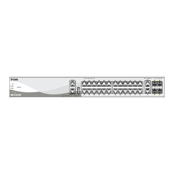
DMS-3130 Series Layer 3 Stackable Managed Switch Hardware Installation Guide 2. Hardware Components This chapter describes the front, rear, and side panel components of all switches in the series. DMS-3130-30TS Switch DMS-3130-30PS Switch DMS-3130-30TS Switch Front Panel Components The front panel of DMS-3130-30TS features a variety of LED indicators and ports. - Page 15 DMS-3130 Series Layer 3 Stackable Managed Switch Hardware Installation Guide Figure 2-2 LED indicators for the DMS-3130-30TS Description This LED will light solid green after the Switch has been powered on successfully. This LED will be off when the Switch is no longer receiving power (i.e. powered off).
-
Page 16: Rear Panel Components
DMS-3130 Series Layer 3 Stackable Managed Switch Hardware Installation Guide Description green when a 25 Gbps port is active or blink amber when a 10 Gbps port is active. The LED will be off when there is no link or activity. -
Page 17: Dms-3130-30Ps Switch
DMS-3130 Series Layer 3 Stackable Managed Switch Hardware Installation Guide Figure 2-4 Side panels of the DMS-3130-30TS DMS-3130-30PS Switch Front Panel Components The front panel of DMS-3130-30PS features a variety of LED indicators and ports. Figure 2-5 Front panel view of the DMS-3130-30PS Ports that can be found on the front panel of this switch are listed in the table below. -
Page 18: Led Indicators
DMS-3130 Series Layer 3 Stackable Managed Switch Hardware Installation Guide For a complete list of SFP transceivers that are compatible with this switch, refer to Port Functions in Appendix A - Technical Specifications. LED Indicators Located on the front panel of this switch are LED indicators: Power, Console, RPS, Fan Err, USB, Link/Act indicators for all the ports, and Stack ID. -
Page 19: Rear Panel Components
DMS-3130 Series Layer 3 Stackable Managed Switch Hardware Installation Guide Description active or blink amber when a 100/1000 Mbps port is active. The LED will be off when there is no link or activity. PoE LED (No. 1~24): The right LEDs of the above ports indicate power supply status. -
Page 20: Side Panel Components
DMS-3130 Series Layer 3 Stackable Managed Switch Hardware Installation Guide Component Description Switch GND Use an electrical grounding wire and connect one end of the wire to the Switch GND and the other end of the wire to an electrical grounding point most commonly found on the Switch mounting rack itself. -
Page 21: Installation
DMS-3130 Series Layer 3 Stackable Managed Switch Hardware Installation Guide 3. Installation Installation Guidelines Installing the Switch without a Rack Installing the Switch in a Standard 19" Rack Installing Transceivers into the Transceiver Ports Power On (AC Power) Installing the Redundant Power Supply (RPS) -
Page 22: Installing The Switch In A Standard 19" Rack
DMS-3130 Series Layer 3 Stackable Managed Switch Hardware Installation Guide Installing the Switch in a Standard 19" Rack This section is used to guide the user through installing the Switch into a switch rack. The Switch can be mounted in a standard 19"(1U) rack using the provided mounting brackets. -
Page 23: Power On (Ac Power)
DMS-3130 Series Layer 3 Stackable Managed Switch Hardware Installation Guide The figure below illustrates how to properly insert SFP28 transceivers into the Switch’s SFP28 ports. Figure 3-4 Inserting transceivers into the transceiver ports The SFP28 ports support transceiver form factors: SFP28 and SFP+. A complete list of SFP transceivers compatible with this switch, can be found in Port Functions in Appendix A - Technical Specifications at the end of this document. - Page 24 DMS-3130 Series Layer 3 Stackable Managed Switch Hardware Installation Guide Figure 3-5 Insert Tie Wrap into the Switch 2. Plug the AC power cord into the power socket of the Switch. Figure 3-6 Connect the power cord to the Switch 3.
-
Page 25: Installing The Redundant Power Supply (Rps)
Installing the Redundant Power Supply (RPS) The Redundant Power Supply (RPS) is designed to conform to the wattage requirements of D-Link’s Ethernet and Gigabit switches. The external RPS unit should be enclosed in solid metal case with sockets to connect AC or DC power sources on one end, and to connect to a switch’s internal power supply on the other end. -
Page 26: Dps-500A Series Redundant Power Supply Unit
DMS-3130 Series Layer 3 Stackable Managed Switch Hardware Installation Guide CAUTION: Do not connect the RPS to AC power before the DC power cable is connected. This might damage the internal power supply. CAUTION: Leave at least 15 cm (6 inches) of space at the rear of the Switch when an RPS is installed to prevent cable damage. - Page 27 DMS-3130 Series Layer 3 Stackable Managed Switch Hardware Installation Guide NOTE: This rack-mount chassis supports the following RPS units: DPS-500A/DPS-500DC. The following diagram illustrates how a DPS-500A is installed into a DPS-800. Figure 3–11 Install the DPS-500A in the DPS-800 The DPS-800 can be mounted into a standard 19"...
-
Page 28: Switch Connections
DMS-3130 Series Layer 3 Stackable Managed Switch Hardware Installation Guide 4. Switch Connections Switch to an End Node Switch to Another Switch Switch Stacking Switch to a Server Switch to an End Node An end node is a generic name for edge networking devices that will be connected to this switch. Typical examples of end nodes are Personal Computers (PCs), Notebooks, Access Points, Print Servers, VoIP Phones and more. -
Page 29: Switch Stacking
Figure 4-2 Connecting the Switch to another switch/hub Switch Stacking The DMS-3130 series supports stacking up to 9 switches together while being managed through one console connection on the master switch, or by an IP address through the MGMT port, or by multiple IP addresses through any one of the ports using Telnet, the Web UI, and SNMP. - Page 30 DMS-3130 Series Layer 3 Stackable Managed Switch Hardware Installation Guide Figure 4-3 2-Port Duplex Chain stacking topology (SFP28 ports)
- Page 31 DMS-3130 Series Layer 3 Stackable Managed Switch Hardware Installation Guide Figure 4-4 4-Port Duplex Chain stacking topology (SFP28 ports)
- Page 32 DMS-3130 Series Layer 3 Stackable Managed Switch Hardware Installation Guide The figures below illustrate how switches can be stacked in a Duplex Ring formation using optical fiber cables connected to SFP28 transceivers or DAC with SFP28 connectors where the 2-port or 4-port stacking configuration is used.
- Page 33 DMS-3130 Series Layer 3 Stackable Managed Switch Hardware Installation Guide Figure 4-6 4-port Duplex Ring stacking topology (SFP28 ports)
-
Page 34: Switch To A Server
DMS-3130 Series Layer 3 Stackable Managed Switch Hardware Installation Guide Switch to a Server The Switch is ideal for connecting to a network backbone, server, or server farm. The RJ45 ports operate at a speed of 100/1000 Mbps up to 2.5, 5, or 10 Gbps depending on the model. The SFP28/SFP+ ports operate at a speed of 10 or 25 Gbps. -
Page 35: Switch Management
Switch. Most of the features available through the CLI can be accessed through the Web UI. Web browsers like Microsoft’s Internet Explorer, Mozilla Firefox, or Google Chrome can be used. For more detailed information about the Web UI, refer to the DMS-3130 Series Web UI Reference Guide. Connecting to the Console Port The front panel of the Switch provides an RJ45 console port to connect a remote system for monitoring and configuring the Switch. -
Page 36: Connecting To The Switch For The First Time
DMS-3130 Series Layer 3 Stackable Managed Switch Hardware Installation Guide Select the appropriate serial port (COM1 or COM2). • • Set the data rate to 115200 baud. • Set the data format to 8 data bits, 1 stop bit, and no parity. -
Page 37: Creating A User Account
DMS-3130 Series Layer 3 Stackable Managed Switch Hardware Installation Guide Creating a User Account One of the first and most important tasks will be to create user accounts. Logging in using a predefined administrator- level username will give the user privileged access to the Switch's management software. Also this will prevent unauthorized access to the Switch and record the passwords for future reference. -
Page 38: Connecting To The Mgmt Port
DMS-3130 Series Layer 3 Stackable Managed Switch Hardware Installation Guide Connecting to the MGMT Port The front panel of the Switch features an Out-Of-Band (OOB) RJ45 MGMT port which can be used to connect to a computer using a standard Ethernet cable. A web browser or Telnet client can be used to connect to the Switch using the MGMT port. -
Page 39: Traps
DMS-3130 Series Layer 3 Stackable Managed Switch Hardware Installation Guide In SNMPv1 and SNMPv2c, user authentication is accomplished using 'community strings', which function like passwords. The remote user SNMP application and the Switch SNMP must use the same community string. SNMP packets from any station that has not been authenticated are ignored (dropped). -
Page 40: Web-Based Switch Configuration
DMS-3130 Series Layer 3 Stackable Managed Switch Hardware Installation Guide Web-based Switch Configuration Introduction Logging into the Web UI Web User Interface (Web UI) Introduction Most software functions of the Switch can be managed, configured, and monitored via the embedded HTML Web UI. -
Page 41: Web User Interface (Web Ui)
Switch. This area displays the Switch’s ports and expansion modules. It also shows port activity based on a specific mode. Some management functions, including port monitoring, are accessible from here. Click the D-Link logo to go to the D-Link website. -
Page 42: Web Pages
DMS-3130 Series Layer 3 Stackable Managed Switch Hardware Installation Guide Web Pages In area 2, mentioned above, the following main folders will be available for selecting. Folder Name Description System Features regarding the Switch’s configuration can be viewed and configured in this folder. -
Page 43: Appendix A - Technical Specifications
DMS-3130 Series Layer 3 Stackable Managed Switch Hardware Installation Guide Appendix A - Technical Specifications General Feature Description Data Transfer Rates Standards Full-duplex Ethernet 20 Mbps Fast Ethernet 200 Mbps Gigabit Ethernet 2 Gbps 2.5 Gigabit Ethernet 5 Gbps 5 Gigabit Ethernet... -
Page 44: Performance
DMS-3130 Series Layer 3 Stackable Managed Switch Hardware Installation Guide Feature Description USB Slot Supports a USB 2.0 Type-A flash drive with a maximum current of 1 A. This slot only supports FAT16 and FAT32 file system architectures Power Consumption DMS-3130-30TS: 74.26W (Max.), 43.84W (Standby) - Page 45 DMS-3130 Series Layer 3 Stackable Managed Switch Hardware Installation Guide Location Color Status Description Light off Power off Console Green Light on (Solid) RJ45 console port is active Light off Console off Fan Err Light on (Solid) Fan fail Light off...
-
Page 46: Port Functions
DMS-3130 Series Layer 3 Stackable Managed Switch Hardware Installation Guide Location Color Status Description Amber Light on (Solid) When there is a connection (or link) to a 100/1000 Mbps Ethernet device on any of the ports Light blinking When there is reception or transmission... - Page 47 DMS-3130 Series Layer 3 Stackable Managed Switch Hardware Installation Guide Feature Description SFP+ Ports Compliant with the following standards: IEEE 802.3ae compliance • SFP+ Transceivers Supported: • DEM-431XT: 10GBASE-SR Multi-mode, OM1:33M/OM2:82M/OM3:300M (w/o DDM) DEM-432XT: 10GBASE-LR Single-mode, 10 km (w/o DDM) •...
-
Page 48: Appendix B - Cables And Connectors
DMS-3130 Series Layer 3 Stackable Managed Switch Hardware Installation Guide Appendix B - Cables and Connectors Ethernet Cable When connecting the Switch to another switch, a bridge or hub, a straight-through Cat5/5e/6a/7 cable is necessary. Please review these products for matching cable pin assignment. -
Page 49: Console Cable (Rj45 To Rs-232)
DMS-3130 Series Layer 3 Stackable Managed Switch Hardware Installation Guide Console Cable (RJ45 to RS-232) A console cable is used to connect to the RJ45 console port of the Switch to access the command line interface. The following diagram and table show the standard RJ45 to RS-232 cable and pin assignments. -
Page 50: Redundant Power Supply (Rps) Cable
DMS-3130 Series Layer 3 Stackable Managed Switch Hardware Installation Guide Redundant Power Supply (RPS) Cable When connecting the Switch to an external Redundant Power Supply, an RPS cable is necessary. Please review this product for matching cable pins. The following diagram and table show the standard RPS connector and its pin assignments. -
Page 51: Ce Red Compliance Statement
DMS-3130 Series Layer 3 Stackable Managed Switch Hardware Installation Guide CE RED Compliance Statement Hereby, D-Link Corporation declares that the radio equipment type DWP-1010 is in compliance with Directive 2014/53/EU. The full text of the EU declaration of conformity is available at the following internet address: http://www.dlink.com/uk/en/support/cedoc... -
Page 52: Technical Support
DMS-3130 Series Layer 3 Stackable Managed Switch Hardware Installation Guide Technical Support TECHNICAL SUPPORT TECHNISCHE UNTERSTÜTZUNG ASSISTANCE TECHNIQUE ASISTENCIA TÉCNICA SUPPORTO TECNICO TECHNISCHE ONDERSTEUNING POMOC TECHNICZNA TECHNICKÁ PODPORA TECHNIKAI TÁMOGATÁS TEKNISK STØTTE eu.dlink.com/support TEKNISK SUPPORT TEKNINEN TUKI TEKNISK SUPPORT ASSISTÊNCIA TÉCNICA ΤΕΧΝΙΚΉ...