Table of Contents
Advertisement
Quick Links
Operator's Manual
POWER WAVE
Register your machine:
www.lincolnelectric.com/register
Authorized Service and Distributor Locator:
www.lincolnelectric.com/locator
Save for future reference
Date Purchased
Code:
(ex: 10859)
Serial:
(ex: U1060512345)
IM10040-A
| Issue D ate 13-Feb
© Lincoln Global, Inc. All Rights Reserved.
C300
®
For use with machines having Code Numbers:
11672, 11958
Need Help? Call 1.888.935.3877
to talk to a Service Representative
Hours of Operation:
8:00 AM to 6:00 PM (ET) Mon. thru Fri.
After hours?
Use "Ask the Experts" at lincolnelectric.com
A Lincoln Service Representative will contact you
no later than the following business day.
For Service outside the USA:
Email: globalservice@lincolnelectric.com
Advertisement
Table of Contents

Related Manuals for Lincoln Electric 11672


Summary of Contents for Lincoln Electric 11672
- Page 1 Operator’s Manual POWER WAVE C300 ® For use with machines having Code Numbers: 11672, 11958 Register your machine: Need Help? Call 1.888.935.3877 www.lincolnelectric.com/register to talk to a Service Representative Authorized Service and Distributor Locator: Hours of Operation: www.lincolnelectric.com/locator 8:00 AM to 6:00 PM (ET) Mon. thru Fri.
- Page 2 351040, Miami, Florida 33135 or CSA Standard W117.2-1974. A Free copy of “Arc Welding Safety” booklet E205 is available from the Lincoln Electric Company, 22801 St. Clair Avenue, Cleveland, Ohio 44117-1199. BE SURE THAT ALL INSTALLATION, OPERATION, MAINTENANCE AND REPAIR PROCEDURES ARE PERFORMED ONLY BY QUALIFIED INDIVIDUALS.
- Page 3 SAFETY ARC RAYS can burn. ELECTRIC SHOCK can 4.a. Use a shield with the proper filter and cover kill. plates to protect your eyes from sparks and 3.a. The electrode and work (or ground) circuits the rays of the arc when welding or observing are electrically “hot”...
- Page 4 SAFETY WELDING and CUTTING CYLINDER may explode SPARKS can if damaged. cause fire or explosion. 7.a. Use only compressed gas cylinders 6.a. Remove fire hazards from the welding area. containing the correct shielding gas for the If this is not possible, cover them to prevent process used and properly operating the welding sparks from starting a fire.
- Page 5 SAFETY 5. Toujours porter des lunettes de sécurité dans la zone de PRÉCAUTIONS DE SÛRETÉ soudage. Utiliser des lunettes avec écrans lateraux dans les zones où lʼon pique le laitier. Pour votre propre protection lire et observer toutes les instructions et les précautions de sûreté...
- Page 6 2004/108/EC. It was manufactured in conformity with a national standard that implements a harmonized standard: EN 60974-10 Electromagnetic Compatibility (EMC) Product Standard for Arc Welding Equipment. It is for use with other Lincoln Electric equipment. It is designed for industrial and professional use. Introduction All electrical equipment generates small amounts of electromagnetic emission.
- Page 7 SAFETY Electromagnetic Compatibility (EMC) The size of the surrounding area to be considered will depend on the structure of the building and other activities that are taking place. The surrounding area may extend beyond the boundaries of the premises. Methods of Reducing Emissions Mains Supply Welding equipment should be connected to the mains supply according to the manufacturer’s recommenda- tions.
- Page 8 Electric for advice or information about their use of our products. We respond to our customers based on the best information in our posses- sion at that time. Lincoln Electric is not in a position to warrant or guarantee such advice, and assumes no liability, with respect to such infor- mation or advice.
-
Page 9: Table Of Contents
viii viii TABLE OF CONTENTS Page Installation........................Section A Technical Specifications ....................A-1, A-2 Safety Precautions .......................A-3 Location, Lifting ......................A-3 Stacking ........................A-3 Tilting..........................A-3 Input and Ground Connections ..................A-3 Machine Grounding .......................A-3 High Frequency Protection....................A-3 Input Connection ........................A-4 Input Fuse and Supply Wire ..................A-4 Input Voltage Selection ....................A-4 Power Cord Replacement .....................A-4 Connection Diagram .....................A-5... -
Page 10: Table Of Contents
TABLE OF CONTENTS Page Maintenance ....................Section D Safety Precautions .......................D-1 Routine Maintenance ......................D-1 Periodic Maintenance......................D-1 Calibration Specification.......................D-1 ________________________________________________________________________________ Troubleshooting ....................Section E Safety Precautions....................E-1 How to Use Troubleshooting Guide...............E-1 Using Status LED and Error Fault Codes ..............E-2, E-4 Troubleshooting Guide................E-2 thru E-5 Error Fault Codes ......................E-6, E-7 ________________________________________________________________________________ Wiring Diagram and Dimension Print ............Section F... -
Page 11: Installation
INSTALLATION ® TECHNICAL SPECIFICATIONS - POWER WAVE C300 POWER SOURCE-INPUT VOLTAGE AND CURRENT Input Amperes Input Voltage ± 10% Model Duty Cycle Power Factor @ Idle Power (1 Phase in paren- Rated Output thesis) 30/28/16/14/11 40% rating 208/230/400*/460/575 (53/48/NA/NA/NA) K2675-2 300 Watts Max. - Page 12 INSTALLATION WIRE FEED SPEED RANGE-WIRE SIZE GMAW GMAW WFS RANGE GMAW FCAW MILD STEEL ALUMINUM STAINLESS WIRE SIZES WIRE SIZES WIRE SIZES WIRE SIZES 50 – 700 ipm .025 – .045" .030 – 3/64" .035 – .045" .035 – .052" (1.3 –...
-
Page 13: Safety Precautions
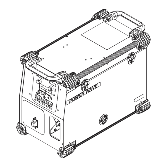
INSTALLATION LIFTING SAFETY PRECAUTIONS Read this Both handles should be used when lifting POWER WAVE ® entire installation section before you start installa- C300. When using a crane or overhead device a lifting strap tion. should be connected to both handles. Do not attempt to lift WARNING the POWER WAVE C300 with accessories attached to it. -
Page 14: Input Connection
INSTALLATION INPUT CONNECTION WARNING WARNING The POWER WAVE C300 ON/OFF ® switch is not intended as a service disconnect for this equipment. Only Only a qualified electrician should a qualified electrician should con- connect the input leads to the nect the input leads to the POWER POWER WAVE C300. -
Page 15: Recommended Work Cable Sizes
INSTALLATION RECOMMENDED WORK CABLE SEMI-AUTOMATIC WELDING SIZES FOR ARC WELDING POLARITY A 15 ft. work cable is provided with the POWER Most GMAW welding procedures use Electrode WAVE C300. This cable is appropriately sized for all ® Positive welding. For these applications, connect the of the POWER WAVE C300ʼs welding procedures. -
Page 16: Cable Connections
INSTALLATION CABLE CONNECTIONS There are two circulars connector in the wire drive compart- ment. (See 4-pin and 12-pin---Figure A.2---Table A.1) TABLE A.1 Function Wiring FIGURE A.2 Supply Voltage for Dual Procedure 4-pin trigger con- Dual Procedure Input nector for push- Trigger Input only guns. -
Page 17: Shielding Gas Connections
INSTALLATION SHIELDING GAS CONNECTION 5. Attach one end of the inlet hose to the outlet fitting of WARNING the flow regulator. Attach the other end to the welding system shielding gas inlet. Tighten the union nuts with a wrench. CYLINDER may explode if damaged. -
Page 18: Loading Spool Wire
INSTALLATION LOADING SPOOLS OF WIRE WARNING • Keep hands, hair, clothing and tools away from rotating equipment. • Do not wear gloves when threading wire or changing wire spool. • Only qualified personnel should install, use or service this equipment. ------------------------------------------------------------------------ Loading 10 to 15 lb. -
Page 19: Wire Drive Configuration
INSTALLATION WIRE DRIVE CONFIGURATION 8. Connect the shielding gas hose to the new gun bushing, if required. (See Figure A.4) 9. Rotate the gun bushing until the thumb screw hole Changing the Gun Receiver Bushing aligns with the thumb screw hole in the feed plate. WARNING Slide the gun receiver bushing into the wire drive and verify the thumb screw holes are aligned. -
Page 20: Gun Used
A-10 A-10 INSTALLATION GUN USED 1. Press end of gun against a solid object that is elec- trically isolated from the welder output and press the gun trigger for several seconds. The Magnum 350PRO is the recommended gun for ® the POWER WAVE C300. -
Page 21: Tig Welding
A-11 A-11 INSTALLATION TIG WELDING SMAW WELDING (Figure A.7) Most SMAW welding procedures use Electrode Tig uses Electrode Negative Polarity so for this appli- Positive welding. For these applications, connect the cation, connect the Tig torch to the negative (-) output stick electrode holder to the positive (+) output stud stud and connect the work clamp to the positive (+) and connect the work clamp to the negative (-) output... -
Page 22: Operation
OPERATION SAFETY PRECAUTIONS GRAPHIC SYMBOLS THAT APPEAR ON THIS MACHINE OR IN THIS MANUAL READ AND UNDERSTAND ENTIRE SECTION BEFORE OPERATING MACHINE. WARNING WARNING OR CAUTION • ELECTRIC SHOCK CAN KILL. Unless using COLD FEED fea- ture, when feeding with gun trig- DANGEROUS ger, the electrode and drive VOLTAGE... -
Page 23: Product Description
OPERATION PROCESS LIMITATIONS PRODUCT DESCRIPTION The software based weld tables of the Power Wave C300 ® The Power Wave C300 is a high performance multi- ® limit the process capability within the output range and the process machine with GMAW, FCAW, SMAW, DC safe limits of the machine. -
Page 24: Design Features
OPERATION DESIGN FEATURES • Patent pending dual spring pressure arms have sensitivity for feeding soft wires without crushing Loaded with Standard Features them, and have plenty of compression force for feeding solid or stiff wires. • Multiple process DC output range: 5 - 300 Amps. •... -
Page 25: Case Front Controls
OPERATION CASE FRONT CONTROLS FIGURE B.1 All operator controls and adjustments are located on 9. ON/OFF SWITCH- Controls power to the Power the case front of the Power Wave. (See Figure B.1) Wave C300. ® 1. LEFT DISPLAY- Shows wire feed speed or amper- 10. -
Page 26: Case Back Controls
OPERATION CASE BACK CONTROLS FIGURE B.2 1. ETHERNET CONNECTOR 2. POWER CORD LOCATION 3. GAS CONNECTION, GMAW AND FCAW 4. GAS CONNECTION, GTAW POWER WAVE C300 ®... -
Page 27: Internal Controls
OPERATION INTERNAL CONTROLS FIGURE B.3 7. 12 PIN CONNECTOR 1. SPINDLE BRAKE 8. NEGATIVE STUD 2. WIRE DRIVE PRESSURE ARM 9. POSITIVE STUD 3. THUMB SCREW, FOR SECURING THE WELDING GUN 10. 4 PIN TRIGGER RECEPTACLE 4. GUN BUSHING 11. COLD INCH / GAS PURGE SWITCH 5. -
Page 28: Making A Weld With Waveform Technology Power Sources
Power Wave at the factory, refer to the Weld Set responsibility of the builder/user. Many variables Reference Guide supplied with the machine or avail- beyond the control of The Lincoln Electric able at www.powerwavesoftware.com. Company affect the results obtained in applying these programs. -
Page 29: Procedure/Memory Panel Operation
OPERATION CASE FRONT CONTROLS USED WIRE FEED SPEED (WFS) VOLTS AMPS TRIM OUTPUT MORE OUTPUT LESS AMPS AMPS SETUP WELD MODE START OPTIONS UltimArc™ Control END OPTIONS DUAL PROCEDURE/ MEMORY PANEL OPERA- TION POWER WAVE C300 ®... - Page 30 OPERATION SMAW (STICK) WELDING SMAW is most often used for outdoor construction, pipe welding and general repairs. The wire feeder controls Amperage, Output Control and Arc Force dur- ing SMAW welding. During SMAW welding the wire drive remains idle. BASIC OPERATION VOLTS TRIM AMPS...
- Page 31 B-10 B-10 OPERATION NON-SYNERGIC GMAW AND FCAW UltimArc™Control, adjusts the apparent inductance of WELDING the wave shape. The UltimArc™Control adjustment is similar to the “pinch” function in that it is inversely pro- In non-synergic modes, the WFS control is similar to a portional to inductance.
- Page 32 B-11 B-11 OPERATION GMAW (MIG) SYNERGIC WELDING Synergic CV programs feature an ideal voltage best suited for most procedures. Use this voltage as a starting point and adjust if needed for personal prefer- For each wire feed speed, a corresponding voltage is ences.
- Page 33 B-12 B-12 OPERATION STEEL AND STAINLESS SYNERGIC GMAW-P (PULSED MIG) WELDING When pulse welding, the power source primarily regu- Trim adjusts the arc length and ranges from 0.50 to 1.50 with a nominal value of 1.00. Increasing the trim lates the arc current, not the arc voltage. During a pulsing cycle, arc current is regulated from a low value increases the arc length.
- Page 34 B-13 B-13 OPERATION STEEL AND STAINLESS GMAW-P (PULSED MIG) WELDING BASIC OPERATION 1.06 VOLTS TRIM AMPS More Shorter Longer Less Deposition Deposition START OPTIONS CONTROL OPTIONS EFFECT DESCRIPTION Postflow Time Adjusts the time that shielding gas flows after the trigger is WELD MODE pulled and prior to feeding wire.
- Page 35 B-14 B-14 OPERATION ALUMINUM SYNERGIC GMAW-P ALUMINUM GMAW-P AND GMAW-PP (PULSED MIG)AND GMAW-PP (PULSE ON PULSE) WELDING ALUMINUM PULSE WELDING Synergic GMAW-P (Pulsed MIG) welding is ideal for low spatter, out of position and reduced heat input The Power Wave C300 can produce top quality alu- ®...
- Page 36 B-15 B-15 OPERATION ALUMINUM GMAW-P (PULSED MIG) AND GMAW-PP (PULSE ON PULSE) WELDING BASIC OPERATION 1.06 VOLTS TRIM AMPS More Longer Shorter Less Deposition Deposition CONTROL OPTIONS START OPTIONS EFFECT DESCRIPTION Postflow Time Adjusts the time that shielding gas flows after the trigger is pulled and prior to feeding wire.
- Page 37 B-16 B-16 OPERATION GTAW (TIG) WELDING The Power Wave C300 is excellent for Touch Start ® TIG welding. BASIC OPERATION Maximum Amperage VOLTS TRIM AMPS OUTPUT OUTPUT CONTROL OPTIONS WELD MODE MODE TOUCH START START OPTIONS No Arc starting Options are active for Touch Start TIG SETUP TOUCH START TIG...
- Page 38 B-17 B-17 OPERATION DUAL PROCEDURE/MEMORY PANEL USER MEMORIES OPERATION Recall a memory with memory buttons To recall a user memory, press one of the eight user The Dual Procedure/Memory Panel performs three memory buttons. The memory is recalled when the functions: button is released.
- Page 39 B-18 B-18 OPERATION LIMITS Set Limits: Limits allow the welder to adjust the welding proce- Press 5 dure only within a defined range. seconds Each user memory may have a different set of limits. For example, memory 1 can be set to limit the WFS to GUN B 200 through 300 in/min, and memory 2 can be set to limit the WFS to 275 through 310 in/min, while memo-...
- Page 40 B-19 B-19 OPERATION If the passcode does not equal zero (0000), enter the The memory value must always be less than or equal passcode now. If the passcode has been forgotten, a to the high limit, and greater than or equal to the low limit.
- Page 41 B-20 B-20 OPERATION 2-STEP 4-STEP- TRIGGER OPERATION The 2-Step - 4-Step switch changes the function of the gun trigger. 2-Step trigger operation switches the welding output ON-OFF in direct response to the trig- ger. 4-Step trigger operation provides 'trigger interlock' capability and gives the ability to control the amount of time spent in the arc start and arc crater steps.
- Page 42 B-21 B-21 OPERATION EXAMPLE 1 - 2 STEP TRIGGER: Simple operation The simplest trigger operation occurs with a 2 Step trigger and the Start, Crater and Burnback functions all set to OFF. (See Figure B.11) For this sequence, PREFLOW: Shielding gas begins to flow immediately when the gun trigger is pulled.
- Page 43 B-22 B-22 OPERATION EXAMPLE 2 - 2 STEP TRIGGER: Improved Arc Start UPSLOPE: and Arc End. Tailoring the arc start and arc end is a Once the wire touches the work and an arc is estab- common method for reducing spatter and improving lished, both the machine output and the wire feed weld quality.
- Page 44 B-23 B-23 OPERATION EXAMPLE 3 - 2 STEP TRIGGER: Customized Arc WELD: Start, Crater and Arc End. Sometimes it is advanta- After upslope, the power source output and the wire geous to set specific arc start, crater and arc ending feed speed continue at the weld settings.
- Page 45 B-24 B-24 OPERATION EXAMPLE 4 – 4 STEP TRIGGER: Trigger Interlock The 4 step trigger can be configured as a trigger inter- lock. Trigger interlock adds to the welderʼs comfort when making long welds by allowing the trigger to be released after an initial trigger pull.
- Page 46 B-25 B-25 OPERATION UPSLOPE: EXAMPLE 5 - 4 STEP TRIGGER: Manual control of During upslope, the power source output and the wire Start and Crater times with Burnback ON. The 4 step feed speed ramp to the weld settings throughout the trigger sequence gives the most flexibility when the start time.
-
Page 47: Cold Feed/Gas Purge Switch
B-26 B-26 OPERATION COLD FEED/GAS PURGE SWITCH 3. Operation with POWER WAVE C300: ® • Install the spool gun per the installation instructions • Turn the Power Wave C300 input power ON. ® COLD FEED Cold Feed and Gas Purge are com- •... - Page 48 B-27 B-27 OPERATION • The Power Wave C300 is now configured and ® ready to weld in the synergic mode. • Adjustment of the SPD value from the set value has the affect of adjusting trim or arc length. • To increase the arc length;...
-
Page 49: Set-Up Feature Menu
B-28 B-28 OPERATION SETUP MENU FEATURES The Setup Menu gives access to the Setup Configuration. Stored in the setup configuration are user parameters that generally only need to be set at installation. The parameters are grouped as shown in the following table. PARAMETER DEFINITION P.1 through P.99... - Page 50 B-29 B-29 OPERATION USER DEFINED PARAMETERS Parameter Definition Exit Setup Menu This option is used to exit the setup menu. When P.0 is displayed, press the Left Button to exit the setup menu. Wire Feed Speed Units This option selects which units to use for displaying wire feed speed. English = inches/minute wire feed speed units (default).
- Page 51 B-30 B-30 OPERATION USER DEFINED PARAMETERS Parameter Definition Procedure Change Method Selects how remote procedure selection (A/B) will be made. The selected procedure can be changed locally at the user interface by pressing the 'A-Gun-B' button. The following methods can be used to remotely change the selected procedure: •...
- Page 52 B-31 B-31 OPERATION USER DEFINED PARAMETERS Parameter Definition Gun Offset Adjustment This option adjusts the wire feed speed calibration of the pull motor of a push-pull gun. This should only be performed when other possible corrections do not solve any push-pull feeding problems. An rpm meter is required to perform the pull gun motor offset calibration.
- Page 53 All Mode Remote = This setting allows the remote control to function in all weld modes which is how most machines with 6-pin and 7-pin remote control connections operate. This setting was provided so that customers with a mix of Lincoln Electric equipment can have consistent remote control behavior across all of their equipment. (N. American default) Joystick MIG Gun = Use this setting while MIG welding with a push MIG gun with a joystick control.
- Page 54 B-33 B-33 OPERATION USER DEFINED PARAMETERS Parameter Definition P.22 Arc Start/Loss Error Time This option can be used to optionally shut off output if an arc is not established, or is lost for a specified amount of time. Error 269 will be displayed if the machine times out. If the value is set to OFF, machine output will not be turned off if an arc is not established nor will output be turned off if an arc is lost.
- Page 55 B-34 B-34 OPERATION USER DEFINED PARAMETERS Parameter Definition P.100 View Diagnostic? Diagnostics are only used for servicing or troubleshooting the Power Wave system. Select "Yes" to access the diagnostic options in the menu. Additional parameters will now appear in the setup menu (P.101, P.102, etc). P.102 View Fatal Logs Used for viewing all the system fatal logs.
- Page 56 B-35 B-35 OPERATION USER DEFINED PARAMETERS Parameter Definition P.503 Memory Button Disable Disables the specified memory button(s). When a memory is disabled, welding procedures can- not be restored from or saved to that memory. If an attempt is made to save or restore a dis- abled memory, a message will be displayed on the lower display indicating the memory number is disabled.
-
Page 57: Accessories
ACCESSORIES OPTIONS / ACCESSORIES K870 FOOT AMPTROL Requires K2909-1, 6-pin to 12-pin adapter. STICK OPTIONS K875 ACCESSORY KIT - 150 Amp K870-2 FOOT AMPTROL (12-pin plug connection) For stick welding. Includes 20 ft. Depress pedal to increase current. Depressing pedal (6.1m) #6 electrode cable with lug, fully achieves maximum set current. -
Page 58: Wire Feed Options
ACCESSORIES WIRE FEEDER OPTIONS K2447-1 PYTHON-PLUS PUSH-PULL GUN Air-Cooled, 15 ft.(4.5m). Requires K2910-1, 7-pin to 12-pin adapter. K2447-2 PYTHON-PLUS PUSH-PULL GUN Air-Cooled, 25 ft.(7.6m). Requires K2910-1, 7-pin to 12-pin adapter. K2447-3 PYTHON-PLUS PUSH-PULL GUN Air-Cooled, 50 ft.(15.2m). Requires K2910-1, 7-pin to 12-pin adapter. - Page 59 MAINTENANCE SAFETY PRECAUTIONS WARNING ELECTRIC SHOCK can kill. • Do not operate with covers removed. • Turn off power source before installing or servicing. • Do not touch electrically hot parts. • Turn the input power to the welding power source off at the fuse box before working in the terminal strip.
- Page 60 HOW TO USE TROUBLESHOOTING GUIDE WARNING Service and Repair should only be performed by Lincoln Electric Factory Trained Personnel. Unauthorized repairs performed on this equipment may result in danger to the technician and machine operator and will invalidate your factory warranty. For your safety and to avoid Electrical Shock, please observe all safety notes and precautions detailed throughout this manual.
- Page 61 TROUBLESHOOTING USING THE STATUS LED TO There is an audible beeper associated with this input control boardʼs status light. So the error codes on the input board TROUBLESHOOT SYSTEM PROBLEMS can be detected through either the status light or the status beeper.
- Page 62 TROUBLESHOOTING Observe all Safety Guidelines detailed throughout this manual ERROR CODES FOR THE POWER WAVE ® The following is a partial list of possible error codes for the POWER WAVE C300. For a complete listing consult ® the Service Manual for this machine. MAIN CONTROL BOARD ( “STATUS”...
- Page 63 TROUBLESHOOTING Observe all Safety Guidelines detailed throughout this manual INPUT CONTROL BOARD Error Code # Indication Peak input current limit Input current limit has been exceeded. Typically indicates short term power overload. If problem persists contact Service Department. Under-voltage lockout +15 VDC supply on Input control board too low.
- Page 64 3. Contact your local authorized 3. Major physical or electrical dam- Lincoln Electric Field Service age is evident when the covers facility for technical assistance. are removed. 1. Make sure input supply discon- Machine will not power up (no lights) 1.
- Page 65 TROUBLESHOOTING Observe all Safety Guidelines detailed throughout this manual PROBLEMS POSSIBLE RECOMMENDED (SYMPTOMS) CAUSE COURSE OF ACTION Thermal LED is ON Improper fan operation Basic Machine Problems (Continued) 1. Check for proper fan operation. Thermal LED is ON 1. Improper fan operation. Fan should run in a low speed setting when the machine is idle and in a high speed when the...
- Page 66 TROUBLESHOOTING Observe all Safety Guidelines detailed throughout this manual PROBLEMS POSSIBLE RECOMMENDED (SYMPTOMS) CAUSE COURSE OF ACTION Weld and Arc Quality Problems (Continued) Wire burns back to tip at the end of 1. Burnback Time 1. Reduce burnback time and/or the weld.
- Page 67 TROUBLESHOOTING Observe all Safety Guidelines detailed throughout this manual PROBLEMS POSSIBLE RECOMMENDED (SYMPTOMS) CAUSE COURSE OF ACTION Ethernet Cannot Connect 1. Physical connection. 1. Verify that the correct patch cable or cross over cable is being used (refer to local IT department for assistance).
- Page 68 DIAGRAMS POWER WAVE C300 ®...
- Page 69 DIMENSION PRINT 27.43 18.80 6.93 13.94 24.04 POWER WAVE C300 ®...
- Page 70 NOTES POWER WAVE C300 ®...
- Page 71 NOTES POWER WAVE® C300...
- Page 72 NOTES POWER WAVE® C300...
- Page 73 Do not touch electrically live parts or Keep flammable materials away. Wear eye, ear and body protection. WARNING electrode with skin or wet clothing. Insulate yourself from work and ground. Spanish No toque las partes o los electrodos Mantenga el material combustible Protéjase los ojos, los oídos y el AVISO DE bajo carga con la piel o ropa moja-...
- Page 74 Keep your head out of fumes. Turn power off before servicing. Do not operate with panel open or WARNING Use ventilation or exhaust to guards off. remove fumes from breathing zone. Spanish Los humos fuera de la zona de res- Desconectar el cable de ali- No operar con panel abierto o AVISO DE...
- Page 75 Need Help? Lincoln Electric “Rapid Response” Service! Call 1.888.935.3877 to talk to a Service Representative Hours of Operation: 8:00 AM to 6:00 PM (ET) Mon. thru Fri. After hours? Use “Ask the Experts” at lincolnelectric.com A Lincoln Service Representative will contact you no later than the following business day.