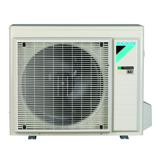
Daikin RXF50B2V1B Installation Manual
R32 split series
Hide thumbs
Also See for RXF50B2V1B:
- Installer's reference manual (76 pages) ,
- Installation manual (28 pages) ,
- Installation manual (16 pages)
Summary of Contents for Daikin RXF50B2V1B
- Page 1 Installation manual R32 split series RXF50B2V1B RXF60B2V1B RXF71A2V1B RXP50L2V1B Installation manual RXP60L2V1B English R32 split series RXP71L2V1B...
- Page 2 2P518197-1A...
- Page 3 2P518197-1A...
-
Page 4: Table Of Contents
About the refrigerant ........... Daikin website (publicly accessible). 4.4.3 To determine the additional refrigerant amount ..▪ The full set of latest technical data is available on the Daikin 4.4.4 To determine the complete recharge amount ..... extranet (authentication required). -
Page 5: Preparation
3 Preparation Preparation Preparing the installation site CAUTION ▪ Check if the installation location can support the unit's weight. Poor installation is hazardous. It can also cause vibrations or unusual operating noise. ▪ Provide sufficient service space. ▪ Do NOT install the unit so that it is in contact with a ceiling or a wall, as this may cause vibrations. -
Page 6: Preparing Refrigerant Piping
4 Installation Preparing refrigerant piping 3.2.1 Refrigerant piping requirements ▪ Piping material: Phosphoric acid deoxidised seamless copper. ▪ Piping diameter: Liquid piping Ø6.4 mm (1/4") Gas piping Ø12.7 mm (1/2") ▪ Piping temper grade and thickness: Outer diameter Temper grade Thickness (t) (Ø) Ø... -
Page 7: To Install The Outdoor Unit
4 Installation Drain port Bottom frame Drain plug Hose (field supply) Make sure that condensation water can be evacuated properly. To close the drain holes and attach the drain socket NOTICE In cold areas, do NOT use a drain socket, hose and caps (1, 2) with the outdoor unit. -
Page 8: Guidelines When Connecting The Refrigerant Piping
4 Installation 2 Connect the gas refrigerant connection from the indoor unit to 4.2.1 Guidelines when connecting the the gas stop valve of the outdoor unit. refrigerant piping NOTICE Piping size Tightening Flare Flare shape It is recommended that the refrigerant piping between (mm) torque (N•m) dimensions (A) -
Page 9: Charging Refrigerant
4 Installation WARNING Charging refrigerant The appliance shall be stored in a room without continuously operating ignition sources (example: open 4.4.1 About charging refrigerant flames, an operating gas appliance or an operating electric The outdoor unit is factory charged with refrigerant, but in some heater). -
Page 10: To Fix The Fluorinated Greenhouse Gases Label
4 Installation 3 Open the gas stop valve. WARNING Keep the interconnection wiring away from copper pipes 4.4.6 To fix the fluorinated greenhouse gases without thermal insulation as such pipes will be very hot. label DANGER: RISK OF ELECTROCUTION 1 Fill in the label as follows: All electrical parts (including thermistors) are powered by Contains fluorinated greenhouse gases the power supply. -
Page 11: Finishing The Outdoor Unit Installation
5 Commissioning Commissioning NOTICE NEVER operate the unit without thermistors and/or 50 Hz 220-240 V pressure sensors/switches. Burning of the compressor might result. Interconnection cable Power supply cable Checklist before commissioning Field fuse Earth leakage circuit breaker Do NOT operate the system before the following checks are OK: Power supply Earth The indoor unit is properly mounted. -
Page 12: Troubleshooting
6 Troubleshooting 2 When the test run is finished, set the temperature to a normal NOTICE level. In cooling mode: 26~28°C, in heating mode: 20~24°C. During pump down operation, stop the compressor before 3 The system stops operating 3 minutes after the unit is turned removing the refrigerant piping. -
Page 13: Technical Data
8 Technical data Technical data A subset of the latest technical data is available on the regional Daikin website (publicly accessible). The full set of latest technical data is available on the Daikin extranet (authentication required). Wiring diagram The wiring diagram can be found inside the outdoor unit (bottom side of the top plate). -
Page 14: Piping Diagram
8 Technical data Piping diagram 8.2.1 Piping diagram: Outdoor unit Applicable for: RXP50L2V1B, RXF50B2V1B Refrigerant flow Heat exchanger Outdoor temperature Thermistor Cooling Heat exchanger thermistor Heating Capillary tube ·1· ·7.0· CuT ·4.0· CuT ·7.0· CuT ·6.4· CuT ·6.4· CuT ·7.0· CuT Capillary tube ·2·... - Page 15 8 Technical data Applicable for: RXP60L2V1B, RXP71L2V1B, RXF60B2V1B, RXF71A2V1B Refrigerant flow Heat exchanger Outdoor temperature Thermistor Cooling Heat exchanger thermistor ·7.0· CuT ·7.0· CuT Heating Capillary tube ·1· ·4.0· CuT ·7.0· CuT ·7.0· CuT Capillary tube ·2· ·6.4· CuT ·6.4· CuT ·4.0·...
- Page 16 3P512025-4C 2018.01...


