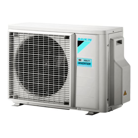
Daikin R32 Split Series Installation Manual
Hide thumbs
Also See for R32 Split Series:
- Installer's reference manual (120 pages) ,
- Operation manual (116 pages) ,
- User reference manual (52 pages)
Table of Contents

Summary of Contents for Daikin R32 Split Series
- Page 1 Installation manual R32 Split series 2MXM68N2V1B 3MXM40N2V1B9 3MXM40N2V1B8 3MXM52N2V1B9 3MXM52N2V1B8 3MXM68N2V1B9 3AMXM52N2V1B9 4MXM68N2V1B9 4MXM80N2V1B9 5MXM90N2V1B9 3AMXF52A2V1B9 Installation manual 3MXF52A2V1B9 English R32 Split series 3MXF68A2V1B9...
- Page 2 2P427092-20V...
- Page 3 2P427092-20V...
- Page 4 2P630134-1...
- Page 5 2P630134-1...
- Page 6 2P630134-4...
- Page 7 2P630134-4...
-
Page 8: Table Of Contents
▪ A subset of the latest technical data is available on the regional Daikin website (publicly accessible). 10 Commissioning ▪ The full set of latest technical data is available on the Daikin 10.1 Checklist before commissioning..........19 Business Portal (authentication required). -
Page 9: Specific Installer Safety Instructions
Use an all-pole disconnection type breaker with at least the inside of the flare. Use refrigeration oil for R32. 3 mm between the contact point gaps that provide full ▪ Do NOT reuse joints. disconnection under overvoltage category III. 2MXM68+3(A)MXM+3(A)MXF+4MXM+5MXM Installation manual R32 Split series 3P600450-1D – 2020.08... -
Page 10: About The Box
"Sound spectrum" in the data book due to Outdoor unit installation manual General safety precautions environmental noise and sound reflections. Fluorinated greenhouse gases label Installation manual 2MXM68+3(A)MXM+3(A)MXF+4MXM+5MXM R32 Split series 3P600450-1D – 2020.08... -
Page 11: Additional Installation Site Requirements Of The Outdoor Unit In Cold Climates
To close the drain holes and attach the drain socket 1 Install drain caps (accessory f) and (accessory g). Make sure the edges of the drain caps close off the holes completely. 2MXM68+3(A)MXM+3(A)MXF+4MXM+5MXM Installation manual R32 Split series 3P600450-1D – 2020.08... -
Page 12: Piping Installation
12.7 mm (1/2") 15.9 mm (5/8") ≥1 mm Depending on the applicable legislation and the maximum working pressure of the unit (see "PS High" on the unit name plate), larger piping thickness might be required. Installation manual 2MXM68+3(A)MXM+3(A)MXF+4MXM+5MXM R32 Split series 3P600450-1D – 2020.08... -
Page 13: Connecting The Refrigerant Piping
A + B (Ø9.5 mm) 15, 20, 25, 35, (42) — C (Ø12.7mm) 15, 20, 25, 35, (42) 42, 50, 60 — D + E (Ø15.9 mm) 15, 20, 25, 35, (42) 42, 50, 60 — 2MXM68+3(A)MXM+3(A)MXF+4MXM+5MXM Installation manual R32 Split series 3P600450-1D – 2020.08... -
Page 14: To Connect The Refrigerant Piping To The Outdoor Unit
Ø15.9 62~75 ▪ Soap water contains ammonia which may lead to corrosion of flared joints (between the brass flare nut and the copper flare). Installation manual 2MXM68+3(A)MXM+3(A)MXF+4MXM+5MXM R32 Split series 3P600450-1D – 2020.08... -
Page 15: To Perform Vacuum Drying
(example: open charge is: the factory refrigerant charge (see unit name flames, an operating gas appliance or an operating electric plate) + the determined additional amount. heater). 2MXM68+3(A)MXM+3(A)MXF+4MXM+5MXM Installation manual R32 Split series 3P600450-1D – 2020.08... -
Page 16: To Charge Additional Refrigerant
S70 - fan motor lead wire connector wiring regulations. S80 - 4-way valve lead wire connector Compressor lead wire connector WARNING *May differ depending on the model. ALWAYS use multicore cable for power supply cables. Installation manual 2MXM68+3(A)MXM+3(A)MXF+4MXM+5MXM R32 Split series 3P600450-1D – 2020.08... -
Page 17: Specifications Of Standard Wiring Components
Make sure to match the symbols 9 Reattach the switch box cover and the service cover. for piping and wiring. 3 Make sure to connect correct wiring to correct room. 2MXM68+3(A)MXM+3(A)MXF+4MXM+5MXM Installation manual R32 Split series 3P600450-1D – 2020.08... -
Page 18: Finishing The Outdoor Unit Installation
To turn on the night quiet mode 2 Disconnect the selective standby electricity saving connector. 1 Remove the switch cover on the service PCB. 3 Turn on the main power supply. Installation manual 2MXM68+3(A)MXM+3(A)MXF+4MXM+5MXM R32 Split series 3P600450-1D – 2020.08... -
Page 19: About Heat Mode Lock
The indoor unit receives the signals of the user interface. The specified wires are used for the interconnection cable. The fuses, circuit breakers, or locally installed protection devices are installed according to this document, and have NOT been bypassed. 2MXM68+3(A)MXM+3(A)MXF+4MXM+5MXM Installation manual R32 Split series 3P600450-1D – 2020.08... -
Page 20: Checklist During Commissioning
▪ When the power turns back on after a power break, the previously selected mode will be resumed. 2 Press the wiring error check switch (SW3) on the outdoor unit service PCB. Installation manual 2MXM68+3(A)MXM+3(A)MXF+4MXM+5MXM R32 Split series 3P600450-1D – 2020.08... -
Page 21: Starting Up The Outdoor Unit
▪ A subset of the latest technical data is available on the regional Daikin website (publicly accessible). Intelligent eye sensor ▪ The full set of latest technical data is available on the Daikin IPM* Intelligent power module Business Portal (authentication required). -
Page 22: Piping Diagram: Outdoor Unit
Gas stop valve S1PH High pressure switch (automatic reset) Capillary tube Liquid stop valve Distributor Electronic expansion valve Refrigerant flow: cooling Muffler with filter Thermistor (liquid) Refrigerant flow: heating Solenoid valve Filter Installation manual 2MXM68+3(A)MXM+3(A)MXF+4MXM+5MXM R32 Split series 3P600450-1D – 2020.08... - Page 23 Gas stop valve S1PH High pressure switch (automatic reset) Capillary tube Liquid stop valve Distributor Electronic expansion valve Refrigerant flow: cooling Muffler with filter Thermistor (liquid) Refrigerant flow: heating Solenoid valve Filter 2MXM68+3(A)MXM+3(A)MXF+4MXM+5MXM Installation manual R32 Split series 3P600450-1D – 2020.08...
- Page 24 Gas stop valve S1PH High pressure switch (automatic reset) Capillary tube Liquid stop valve Distributor Electronic expansion valve Refrigerant flow: cooling Muffler with filter Thermistor (liquid) Refrigerant flow: heating Solenoid valve Filter Installation manual 2MXM68+3(A)MXM+3(A)MXF+4MXM+5MXM R32 Split series 3P600450-1D – 2020.08...
- Page 25 Gas stop valve S1PH High pressure switch (automatic reset) Capillary tube Liquid stop valve Distributor Electronic expansion valve Refrigerant flow: cooling Muffler with filter Thermistor (liquid) Refrigerant flow: heating Solenoid valve Filter 2MXM68+3(A)MXM+3(A)MXF+4MXM+5MXM Installation manual R32 Split series 3P600450-1D – 2020.08...
- Page 28 3P600450-1D 2020.08 Verantwortung für Energie und Umwelt...


