Advertisement
Quick Links
Installation Guide
D103097X014
English – December 2022
Introduction
This installation guide provides instructions for installation,
startup and adjustment. To receive a copy of the
instruction manual, contact your local Sales Office or view
a copy at www.fisher.com. For further information refer to:
67C Series Instruction Manual, D102601X012.
PED Categories
This product may be used as a safety accessory with
pressure equipment in the following Pressure Equipment
Directive categories. It may also be used outside of the
Pressure Equipment Directive using Sound Engineering
Practice (SEP) per table below. For information on the
current PED revision see Bulletin: D103053X012.
PRODUCT SIZE
CATEGORIES
1/4 NPT
Specifications
Body Size and End Connection Style
1/4 NPT
Maximum Inlet Pressure (Body Rating)
67CFS Series: 17.2 bar / 250 psig
67CS Series: 27.6 bar / 400 psig
Maximum Emergency Outlet Pressure
3.4 bar / 50 psig over outlet pressure setting
Proof Test Pressure
All Pressure Retaining Components have been
proof tested per Directive.
Outlet Pressure Ranges
0 to 1.4 bar / 0 to 20 psig
0 to 2.4 bar / 0 to 35 psig
0 to 4.1 bar / 0 to 60 psig
0 to 8.6 bar / 0 to 125 psig
0 to 10.3 bar / 0 to 150 psig
Temperature Capabilities
With Nitrile (NBR)
Standard Bolting: -29 to 82°C / -20 to 180°F
Stainless Steel Bolting: -40 to 82°C / -40 to 180°F
With Fluorocarbon (FKM)
Polyethylene Filter
(3)
0 to 180°F
Stainless steel or Glass Filter (Optional):
-18 to 149°C / 0 to 300°F
With Silicone (VMQ)
Temperature bolting: -51 to 82°C / -60 to 180°F
With Gauges: -40 to 82°C / -40 to 180°F
1. The pressure/temperature limits in this installation guide or any applicable standard
limitation should not be exceeded.
2. Silicone (VMQ) is not compatible with hydrocarbon gas.
3. Do not use in high aromatic hydrocarbon service.
FLUID TYPE
SEP
1
(1)
(1)
(1)
(1)
(standard): -18 to 82°C /
Diaphragm and Low
(2)
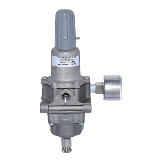
67CS and 67CFS Series
Installation
▲
Only qualified personnel should install
or service a regulator. Regulators should
be installed, operated and maintained
in accordance with international and
applicable codes and regulations and
Emerson Process Management Regulator
Technologies, Inc. instructions.
If the regulator vents fluid or a leak
develops in the system, it indicates that
service is required. Failure to take the
regulator out of service immediately may
create a hazardous condition.
Personal injury, equipment damage or
leakage due to escaping fluid or bursting
of pressure-containing parts may result
if this regulator is overpressured or
is installed where service conditions
could exceed the limits given in the
Specifications section, or where
conditions exceed any ratings of the
adjacent piping or piping connections.
To avoid such injury or damage, provide
pressure-relieving or pressure-limiting
devices (as required by the appropriate
code, regulation or standard) to prevent
service conditions from exceeding limits.
Additionally, physical damage to the
regulator could result in personal injury
and property damage due to escaping
fluid. To avoid such injury and damage,
install the regulator in a safe location.
The internal relief valve in the
67CFSR Series regulators does not
provide full overpressure protection. The
internal relief valve is designed for minor
seat leakage only.
Clean out all pipelines before installation of the
regulator and check to be sure the regulator has not
been damaged or has collected foreign material during
shipping. For NPT bodies, apply pipe compound to the
external pipe threads. For flanged bodies, use suitable
line gaskets and approved piping and bolting practices.
Install the regulator in any position desired, unless
otherwise specified, but be sure flow through the body
is in the direction indicated by the arrow on the body.
WARNING
Advertisement

Related Manuals for Emerson Fisher 67CS Series


Summary of Contents for Emerson Fisher 67CS Series
- Page 1 This product may be used as a safety accessory with Emerson Process Management Regulator pressure equipment in the following Pressure Equipment Technologies, Inc. instructions. Directive categories. It may also be used outside of the...
- Page 2 67CS and 67CFS Series Parts List Note It is important that the regulator be Types 67CS and 67CSR installed so that the vent hole in the spring case is unobstructed at all times. Description For outdoor installations, the regulator Body should be located away from vehicular Flange Screw traffic and positioned so that water, ice...
- Page 3 67CS and 67CFS Series 13 / 0.50 SPACER OUTER DIAMETER 4.6 / 0.18 SPACER B2697 8.1 / 0.32 SPACER WIDTH AND mm / INNER DIAMETER Figure 1. Spacer Diameter and Assembly (For Installing in an Existing Installation if the Mounting Bolts are Too Long) GE03521 APPLY LUBRICANT 40C1728...
- Page 4 Technologies, Inc. All rights reserved. 12/22. McKinney, Texas 75070 USA Singapore 128461, Singapore The Emerson logo is a trademark and service mark of Emerson T +1 800 558 5853 T +65 6777 8211 Electric Co. All other marks are the property of their prospective owners.