Table of Contents
Advertisement
Instruction Manual
D100306X012
Fisherr 657 Diaphragm Actuator
Sizes 30-70 and 87
Contents
. . . . . . . . . . . . . . . . . . . . . . . . . . . . . . . . .
. . . . . . . . . . . . . . . . . . . . . . . . . . . . .
. . . . . . . . . . . . . . . . . . . . . . . . . . . . . . . . .
. . . . . . . . . . . . . . . . . . . . . . . . . . . . . . .
. . . . . . . . . . . . . . . . . . . . . . . . . . . . . . . . . . .
. . . . . . . . . . . . . . . . . . . . . . . . . . .
. . . . . . . . . . . . . . . . . . . . . . . . .
. . . . . . . . . . . . . . . . . . . . . . . . . . . . . . . .
. . . . . . . . . . . . . . . . . . . . . . . . .
. . . . . . . . . . . . . . . . . . . . . . . . . . . . . . .
. . . . . . . . . . . . . . . . . . . . . . . . . . . . . . . . . . .
. . . . . . . . . . . . . . . . . . . . . . . . . . . . . . . . . . .
Introduction
Scope of Manual
This instruction manual provides information on installation, adjustment, maintenance, and parts ordering for the
Fisher 657 actuator in sizes 30 through 70 and size 87. The 657-4 actuator in sizes 70 and 87 is also covered. Refer to
separate instruction manuals for information about the valve positioner and other accessories used with these
actuators.
www.Fisher.com
. . . . . . . . . . . .
. . . . . . . . . . . . . . . . . . . . . . .
. . . . . . . . .
. . . . . . . . . . . . . . . . . . . . . .
. . . . . . . . . . . . . . . . . . . . . . .
. . . . . . . . . . .
. . . . . . . . . . . . . . . . . . . . .
. . . . . . .
. . . . . . . . . . . . .
. . . . . . . . . . . . .
. . . . . . . . . .
. . . . . .
. . . . . .
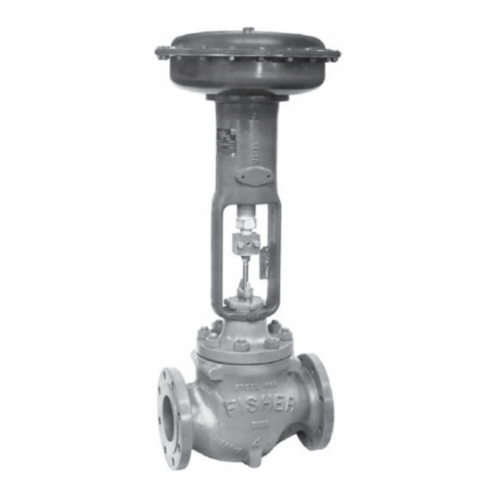
Figure 1. Fisher 657 or 657-4 Actuator Mounted
on an easy-e™ Valve
1
1
2
2
3
5
6
7
8
8
10
10
11
12
14
15
17
19
19
19
19
W2174-2
21
21
22
22
657 Actuator (30-70 and 87)
. . . . . . . . . . . . . . . . . . . . . . . . .
. . . . . . . . . . . . . . . . . . . . . . . . . . . . . .
December 2010
26
27
Advertisement
Table of Contents

Related Manuals for Emerson FISHER 657


Summary of Contents for Emerson FISHER 657
-
Page 1: Table Of Contents
This instruction manual provides information on installation, adjustment, maintenance, and parts ordering for the Fisher 657 actuator in sizes 30 through 70 and size 87. The 657‐4 actuator in sizes 70 and 87 is also covered. Refer to separate instruction manuals for information about the valve positioner and other accessories used with these actuators. -
Page 2: Description
4. Normal operating diaphragm pressure must not exceed maximum diaphragm casing pressure and must not produce a force on the actuator stem greater than the maximum allowable out put thrust or the maximum allowable valve stem load. Contact your Emerson Process Management sales office with questions concerning maximum allowable valve stem load. -
Page 3: Specifications
If repeated or daily manual operation is expected, the actuator should be equipped with a side‐mounted handwheel rather than a casing‐mounted travel stop or top‐mounted handwheel. The side‐mounted handwheel is designed for more frequent use as a manual operator. Figure 2. Schematic of Fisher 657 and 657‐4 Actuators AF3833‐A A0792‐2 Specifications Refer to table 1 for Specifications of the 657 and 657‐4 actuators. - Page 4 To avoid parts damage, do not use an operating pressure that exceeds the Maximum Diaphragm Casing Pressure (table 1) or produces a force on the actuator stem greater than the Maximum Allowable Output Thrust (table 1) or the maximum allowable valve stem load. (Contact your Emerson Process Management sales office with questions concerning maximum allowable valve stem load.) D Valve/Actuator Assembly: If the actuator and valve are shipped together as a control valve assembly, it has been...
-
Page 5: Mounting The Actuator On The Valve
Instruction Manual D100306X012 Figure 4. Bench Set Adjustment SPRING ADJUSTER LOWER BENCH SET LOADING PRESSURE UPPER BENCH SET PRESSURE MARK VALVE STEM NOTES: THE LOWER PSIG LOADING PRESSURE (MARKED ON NAMEPLATE) WHERE THE FIRST MOVEMENT OF ACTUATOR STEM IS DETECTED. THE UPPER PSIG LOADING PRESSURE EXTENDS ACTUATOR STEM. -
Page 6: Discussion Of Bench Set
657 Actuator (30-70 and 87) December 2010 1. Provide a vise or some other method of supporting the valve and the weight of the actuator during assembly. For direct or reverse acting valves, push the valve stem down away from the actuator while mounting the actuator. 2. -
Page 7: Spring Verification
Instruction Manual D100306X012 5. Calculate the actual friction force: Friction Force, = 0.5 pounds Refer to table 1 for the effective diaphragm area. When determining valve friction, you can make diaphragm pressure readings at a travel position other than mid‐travel if you desire. -
Page 8: Installing The Stem Connector Assembly
Catalog 14, Actuator Sizing and Sample Calculation sections to determine the correct spring selection for your application. Or, contact your Emerson Process Management sales office for assistance. After replacing the spring, repeat the steps above. -
Page 9: Deadband Measurement
Instruction Manual D100306X012 matches the valve travel on the travel indicator plate. If valve travel is not correct, repeat the stem connector procedure. Figure 5. Typical Valve Response to Deadband UPPER BENCH SET PRESSURE LOWER BENCH SET PRESSURE OPEN MID RANGE VALVE TRAVEL DIRECT ACTING VALVE NOTE:... -
Page 10: Loading Connection
657 Actuator (30-70 and 87) December 2010 Loading Connection The loading pressure connections are made at the factory if the valve, actuator, and positioner come as a unit. Keep the length of tubing or piping as short as possible to avoid transmission lag in the control signal. If a volume booster, valve positioner or other accessory is used, be sure that it is properly connected to the actuator. -
Page 11: Actuator Maintenance
Instruction Manual D100306X012 Actuator Maintenance This procedure describes how the actuator can be completely disassembled and assembled. When inspection or repairs are required, disassemble only those parts necessary to accomplish the job; then, start the assembly at the appropriate step. Key numbers refer to figures 6, 7, or 8 unless otherwise indicated. -
Page 12: Top-Mounted Handwheel Assembly
657 Actuator (30-70 and 87) December 2010 6. Position the upper diaphragm casing (key 1) on the diaphragm (key 2) and align the holes. Note When you replace actuator diaphragms in the field, take care to ensure the diaphragm casing bolts are tightened to the proper load to prevent leakage, but not crush the material. - Page 13 Instruction Manual D100306X012 WARNING To avoid personal injury from the precompressed spring force thrusting the upper diaphragm casing (key 1) away from the actuator, thread the spring adjuster (key 12) out of the yoke until all spring compression is relieved, then carefully remove casing cap screws (key 22).
-
Page 14: Side-Mounted Handwheel For Sizes 34 Through 60 Actuators
657 Actuator (30-70 and 87) December 2010 CAUTION Over‐tightening the diaphragm casing cap screws and nuts (keys 22 and 23) can damage the diaphragm. Do not exceed 27 NSm (20 lbfSft) torque. Note Do not use lubricant on these bolts and nuts. Fasteners must be clean and dry. 8. -
Page 15: Side-Mounted Handwheel For Sizes 70 And 87 Actuators
Instruction Manual D100306X012 Assembly for Side‐Mounted Handwheel (Size 34‐60) 1. Pack the ball bearings (key 152) with anti‐seize lubricant (key 244). Insert one bearing and the bushing (key 151) into the handwheel body (key 142) as shown in figure 11 or 12. The bushing is not used in a handwheel assembly for sizes 45 through 60 actuators. - Page 16 657 Actuator (30-70 and 87) December 2010 6. Separate the halves of the stem connector assembly (key 26) by removing the two cap screws. Remove the actuator stem (key 10). 7. Remove the travel indicator (key 14). CAUTION To avoid possible product damage, do not move the neutral indicator scale after completing the following step. 8.
-
Page 17: Casing-Mounted Adjustable Travel Stops
Instruction Manual D100306X012 12. Put the spring seat and actuator spring (keys 11 and 6) into the yoke (key 9). Slide the upper sleeve (key 34) onto the actuator stem (key 10). 13. Put the diaphragm plate and washer (keys 4 and 25) onto the actuator stem (key 10). Insert and tighten the cap screw (key 3) to fasten the parts together. -
Page 18: Casing‐Mounted Adjustable Up Travel Stops
657 Actuator (30-70 and 87) December 2010 The casing‐mounted adjustable up travel stop (figures 14 or 15) limits the actuator stroke in the upward direction. To adjust, first relieve actuator loading pressure before removing the travel stop cap (key 187, figure 14 or 15). Loosen the travel stop nut (key 137). -
Page 19: Parts Ordering
Note Neither Emerson, Emerson Process Management, nor any of their affiliated entities assumes responsibility for the selection, use, or maintenance of any product. Responsibility for the selection, use, and maintenance of any product remains with the purchaser and end‐user. - Page 20 657 Actuator (30-70 and 87) December 2010 Figure 6. Fisher 657 Actuator Sizes 30 through 60 APPLY LUB 40A8765-C Figure 7. Fisher 657 Size 70 Actuator APPLY LUB 50A8768-C Instruction Manual D100306X012...
-
Page 21: Parts List
Figure 8. Fisher 657 Size 87 Actuator APPLY LUB 50A8767-C Parts List Note Part numbers are shown for recommended spares only. For part numbers not shown, contact your Emerson Process Management sales office. Actuator Assembly (figures 6, 7, or 8) Description Upper Diaphragm Casing Diaphragm Molded nitrile/nylon... -
Page 22: Top-Mounted Handwheel (Figures 9 Or 10)
657 Actuator (30-70 and 87) December 2010 Description Travel Indicator Scale Nameplate, SST Drive Screw Cap Screw Hex Nut Twin Speed Nut Washer Stem Connector Assy, Steel Zn Pl Sizes 30 & 34 Size 34 with side mtd handwheel Size 40 Size 40 with side mtd handwheel Sizes 45 &... - Page 23 Instruction Manual D100306X012 Figure 9. Top‐Mounted Handwheel Assembly for Size 30 through 60 Actuators APPLY LUB/SEALANT NOTES: THE TOP MOUNTED HANDWHEEL IS NOT DESIGNED FOR USE UN DER HEAVY LOAD OR FOR FREQUENT USE. 28A1205‐D Figure 11. Side‐Mounted Handwheel Assembly for Size 34 and 40 Actuators APPLY LUBRICANT 30A8778‐D 657 Actuator (30-70 and 87)
- Page 24 657 Actuator (30-70 and 87) December 2010 Figure 12. Side‐Mounted Handwheel Assembly for Size 45 and 60 Actuators APPLY LUBRICANT 40A8779‐D Instruction Manual D100306X012...
-
Page 25: Instruction Manual 657 Actuator (30-70 And
Instruction Manual 657 Actuator (30-70 and 87) D100306X012 December 2010 Figure 13. Fisher 657 Size 70 and 87 Actuators with Side‐Mounted Handwheel APPLY LUB 50A8769-D SECTION A-A... -
Page 26: Casing-Mounted Adjustable Up Travel Stops (Figures 14 Or 15)
657 Actuator (30-70 and 87) December 2010 Figure 14. Casing‐Mounted Adjustable Up Travel Stop for Sizes 30 through 60 Actuators (Style 1) APPLY LUBRICANT 28A1206‐C Casing‐Mounted Adjustable Up Travel Stops (figures 14 or 15) Description Travel Stop Stem Pusher Plate Travel Stop Nut 138* O‐Ring, nitrile Sizes 30, 34, &... -
Page 27: Casing-Mounted Adjustable Down Travel Stops (Figure 16)
Instruction Manual D100306X012 Figure 16. Casing‐Mounted Adjustable Down Travel Stop for Size 30 and 40 Actuators (Style 2) APPLY LUB BV8054-E Casing‐Mounted Adjustable Down Travel Stop (figure 16) Description Stop Nut Travel Stop Stem Washer 139* O‐Ring, nitrile Sizes 30, 34, & 40 Sizes 45, 46, 50, &... - Page 28 2. Diaphragm pressure range for this spring & travel combination is 0.2‐2.0 bar (3‐30 psig). Fisher and easy-e are marks owned by one of the companies in the Emerson Process Management business division of Emerson Electric Co. Emerson Process Management, Emerson, and the Emerson logo are trademarks and service marks of Emerson Electric Co. All other marks are the property of their respective owners.