Table of Contents
Advertisement
Manual
Models 1204M/05M/09M/21M
Electronic Motor Controllers
with Universal Logic Board
Read Instructions Carefully!
Specifications are subject to change without notice.
© 2012 Curtis Instruments, Inc. ® Curtis is a registered trademark of Curtis Instruments, Inc.
© The design and appearance of the products depicted herein are the copyright of Curtis Instruments, Inc.
Curtis Instruments, Inc.
200 Kisco Avenue
Mt. Kisco, NY 10549
www.curtisinstruments.com
53121 Rev B 8/16
Advertisement
Table of Contents
Troubleshooting

Related Manuals for Curtis 1204M


Summary of Contents for Curtis 1204M
- Page 1 Specifications are subject to change without notice. © 2012 Curtis Instruments, Inc. ® Curtis is a registered trademark of Curtis Instruments, Inc. © The design and appearance of the products depicted herein are the copyright of Curtis Instruments, Inc. 53121 Rev B 8/16...
-
Page 3: Table Of Contents
CONTENTS CONTENTS 1. OVERVIEW ................... 1 2. INSTALLATION AND WIRING ..........3 Mounting the 1204M/05M Controller ........3 Mounting the 1209M/21M Controller ........4 Connections: High Current ............5 Connections: Low Current ............5 Controller Wiring Configuration, with active main driver ..7 Controller Wiring Configuration, with active reverse input .. - Page 4 FIGURES / TABLES FIGURES . 1: Curtis 1204M and 1209M electronic motor controllers ....1 . 2: Mounting dimensions, Curtis 1204M/05M controllers ....3 . 3: Mounting dimensions, Curtis 1209M/21M controllers .....4 . 4: Standard wiring configuration, with active main driver .....7 .
-
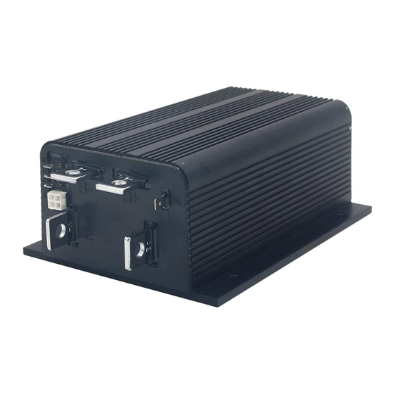
Page 5: Overview
1 — OVERVIEW OVERVIEW Curtis 1204M, 1205M, 1209M, and 1221M series motor controllers are the form/fit/function replacements of the earlier 1204/1205/1209B/1221B con- trollers, with the added functionality of being programmable—via a Curtis handheld programmer or PC programming station. This means the controllers can be tailored to the needs of specific applications. - Page 6 PC programming station. Familiarity with your Curtis 1204M/05M/09M/21M controller will help you install and operate it properly. We encourage you to read this manual carefully. If you have questions, please contact the Curtis office nearest you. Curtis 1204M/1205M/1209M/1221M Manual...
-
Page 7: Installation And Wiring
INSTALLATION AND WIRING MOUNTING THE CONTROLLER The outline and mounting hole dimensions are shown for the 1204M and 1205M controllers in Figure 2, and for the 1209M and 1221M controllers in Figure 3. The controllers meet the IP54 requirements for environmental protection against dust and water. -
Page 8: Mounting The 1209M/21M Controller
Wear safety glasses, and use properly insulated tools to prevent shorts. — Charging or discharging generates hydrogen gas, LEAD ACID BATTERIES which can build up in and around the batteries. Follow the battery man- ufacturer’s safety recommendations. Wear safety glasses. Curtis 1204M/1205M/1209M/1221M Manual... -
Page 9: Connections: High Current
Wire 2 of 2-wire throttle; Pot Wiper of 3-wire throttle; Pot Low of ITS thottle; or electronic throttle input. 4-pin connector: see Table 3. Reverse signal output / main contactor coil driver. For the control wiring, 0.75 mm (#18 AWG) vinyl insulated stranded wire is recommended. Curtis 1204M/1205M/1209M/1221M Manual... -
Page 10: Table 3 J4 Connector Pinout
2 — INSTALLATION & WIRING: Connections The mating connector for is a 4-pin Molex Mini-fit Jr. or equivalent. Either an external Status LED or a Curtis programmer can be connected to J4. The pinout is as follows. Table 3 J4 Connector Pinout PROGRAMMER... -
Page 11: Controller Wiring Configuration, With Active Main Driver
PRECHARGE RESISTOR 24V: 100 , 10 W 36–48V: 250 , 10W 60–72V: 250 , 20 W MOTOR ARMATURE 5k THROTTLE – MOTOR FIELD STATUS B– M– Fig. 4 Basic wiring diagram, Curtis 1204M/05M/09M/21M with active main contactor. Curtis 1204M/1205M/1209M/1221M Manual... -
Page 12: Controller Wiring Configuration, With Active Reverse Input
B– M– Fig. 5 Basic wiring diagram, Curtis 1204M/05M/09M/21M with active reverse input. The throttle shown in the basic wiring diagrams is a 2-wire potentiometer. Various types of throttles can be used; see Throttle Type parameter (page 21) and throttle wiring (pages 10–13). -
Page 13: Forward/Reverse Wiring
HPD and inhibit plug braking. Fig. 6 Control wiring PEDAL to inhibit plug braking, in FUSE KEYSWITCH INTERLOCKS MICROSWITCH order to allow freewheeling. F/R SWITCH POLARITY (DPDT, center off) PROTECTION DIODE – Curtis 1204M/1205M/1209M/1221M Manual... -
Page 14: Throttle Wiring
Type 0 throttles, resistance increases as the applied throttle is increased. Fig. 8 Wiring for Type 0 throttles. Mechanical potboxes and footpedals are Type 0 throttles. It doesn’t matter which wire goes on which terminal, and the wires can be extended as required. Curtis 1204M/1205M/1209M/1221M Manual... -
Page 15: Fig. 9 Wiring For Type 1, 3, 4, And 5 Throttles
A potbox makes it easy to retain the vehicle’s original cable throttle pedal. Curtis and various third-party vendors also offer self-contained footpedal units that eliminate the need for fabricating and installing a pedal-potbox linkage. - Page 16 0–5V signal variation over the full current range. It is the responsibil- ity of the OEM to provide appropriate throttle fault detection. The Curtis ET-XXX electronic throttle contains no built-in fault detec- tion, and the controller will detect only open wiper faults. It is the responsibil- ity of the OEM to provide any additional throttle fault detection necessary.
- Page 17 2 — INSTALLATION & WIRING: Throttle Wiring Fig. 10 Wiring for Type 2 Voltage Source throttles. Current Source Curtis ET-XXX Electronic Throttle – Curtis 1204M/1205M/1209M/1221M Manual...
-
Page 18: Wiring Configuration For Pump Applications
2 — INSTALLATION & WIRING: Throttle Wiring; Pump Applications Basic Wiring Configuration for Pump Applications The 1204M-6302 controller has only three busbars; it is appropriate for use with pump motors, wired as shown in Figure 11. CONTROL WIRING ENABLE KEYSWITCH... -
Page 19: Installation Checkout
Apply the throttle, turn the keyswitch on, and then select a direction. The motor should not run. Release the throttle and re-apply it — the motor should now run. If the motor runs before you release the throttle, recheck the wiring. Curtis 1204M/1205M/1209M/1221M Manual... - Page 20 The vehicle should smoothly brake to a stop and accelerate in reverse. I. On vehicles that are intended to have plug braking inhibited, verify that the maneuver in “H” produces freewheel coasting. Curtis 1204M/1205M/1209M/1221M Manual...
-
Page 21: Programmable Parameters
3 — PROGRAMMABLE PARAMETERS PROGRAMMABLE PARAMETERS The 1204M/05M/09M/21M controllers have a number of parameters that can be adjusted using a Curtis programming device. These programmable parameters allow the vehicle’s performance to be customized to fit the needs of specific applications. -
Page 22: Voltage Parameters
Under Voltage Cutoff 67 – 1 00 % The Under Voltage Cutoff parameter sets the voltage at which controller output will be cut off completely. The programmed value is a percentage of the battery voltage. The Under Voltage Cutoff parameter can only be set to values smaller (lower) than the programmed Under Voltage Cutback. Curtis 1204M/1205M/1209M/1221M Manual... -
Page 23: Current Parameters
The plug braking current limit is set by this parameter. Plug braking can be either fixed or throttle-variable; see Variable Plug parameter (page 23). During fixed plug braking, the plug braking current is the programmed Plug Current Limit value. During variable plug braking, the plug braking current varies with the amount of applied throttle, from 50% to 100% of the programmed Plug Current Limit value. Curtis 1204M/1205M/1209M/1221M Manual... -
Page 24: Speed Parameters
PWM. Partially-applied throttle is scaled proportionately; e.g., 40% applied throttle corresponds to a request for 40% of the programmed Max Speed value. Example: if Max Speed is set to 80%, a 40% applied reverse throttle corresponds to a 32% request (0.80 * 0.40 = 0.32). The Rev Speed parameter is in effect only with the “reverse input active” wiring configuration or with a speed reduction resistor added to the circuit. Curtis 1204M/1205M/1209M/1221M Manual... -
Page 25: Throttle Input Parameters
Values above 50% give the vehicle a faster, more responsive feel at low throttle settings. The Throttle Map value is the controller output at half throttle, as a percentage of the Max Speed. Half throttle is the midpoint of the throttle’s active range, which is the range from zero output (at the Deadband setting) to 100% output (at the Throttle Max setting). Curtis 1204M/1205M/1209M/1221M Manual... -
Page 26: Fig. 12 Effect Of Throttle Adjustment Parameters
80% Map setting. Deadband = 10% Throttle Max = 80%. The unshaded area represents the throttle’s active range. Deadband parameter adjusts this endpoint. THROTTLE POSITION (percentage of full range) Curtis 1204M/1205M/1209M/1221M Manual... -
Page 27: Miscellaneous Parameters
0 – 6 0 s The Main Drop Delay defines the time delay before the main contactor drops out after there has been no active throttle signal. Setting Main Drop Delay = 0 means the main contactor never drops out; it does not mean there is no delay. Curtis 1204M/1205M/1209M/1221M Manual... -
Page 28: Controller Cloning
Plug the programmer into the controller that you want to have these same settings, and select “Write settings to controller.” To perform cloning with the 1313 handheld programmer or 1314 PC Programming Station, use the Programming menu. Curtis 1204M/1205M/1209M/1221M Manual... -
Page 29: Monitor Menu
Heatsink temperature. Throttle Throttle request, as percentage of full throttle. Duty Cycle Controller’s PWM output, as percentage of programmed Max Speed. Cap Voltage Voltage of controller’s internal capacitor bank at B+ busbar. A2 Voltage Voltage on controller’s A2 busbar. Battery Voltage Battery voltage. Motor Voltage Voltage between controller’s B+ and M- busbars. Motor Open On/Off Status of motor connection. Plug Braking On/Off Status of plug braking feature. Curtis 1204M/1205M/1209M/1221M Manual... -
Page 30: Diagnostics And Troubleshooting
5 — DIAGNOSTICS & TROUBLESHOOTING DIAGNOSTICS AND TROUBLESHOOTING The 1204M/05M/09M/21M controllers detect a wide variety of faults or error conditions. Fault information can be obtained in either of two ways: (1) by observing the fault codes issued by the external Status LEDs or (2) by reading the display on a programmer. - Page 31 If not, shut off KSI and remove the J-1, J-2, J-3, and J-5 connectors. Check the connectors for corrosion or damage, clean them if necessary, and re-insert them. Curtis 1204M/1205M/1209M/1221M Manual...
-
Page 32: Table 5 Troubleshooting Chart
3. Loose battery or controller connection. Over Voltage PWM output and main Battery voltage falls below 1. Battery voltage ≥ factory-set contactor disabled. (Over Voltage Cutoff - Over Voltage Cutoff threshold. Over Voltage Hysteresis). 2. Operation with charger attached. Curtis 1204M/1205M/1209M/1221M Manual... - Page 33 (see page 24). Also “Main contactor disabled” only applies when the main contactor is driven by the controller – wiring configuration shown in Figure 4, and Rev Input / Main Driver parameter = 2 (see page 24). Curtis 1204M/1205M/1209M/1221M Manual...
-
Page 34: Maintenance
4. Make sure the connections are tight. DIAGNOSTIC HISTORY The Curtis programming devices can be used to access the controller’s fault history file, via the Faults/Diagnostics menu. The programmer will read out all the faults the controller has experienced since the last time the fault history file was cleared. - Page 35 Signals with high frequency content can produce significant emissions if con- nected to a large enough radiating area (created by long wires spaced far apart). Contactor drivers and the motor drive output from Curtis controllers can contribute to RF emissions. Both types of output are pulse width modulated square waves with fast rise and fall times that are rich in harmonics.
- Page 36 This coupling can be reduced by placing the controller as far as possible from the noise source or by enclosing the controller in a metal box. Some Curtis controllers are enclosed by a heatsink that also provides shielding around the controller circuitry, while others are partially shielded or unshielded.
- Page 37 ELECTROSTATIC DISCHARGE (ESD) Curtis motor controllers contain ESD-sensitive components, and it is therefore necessary to protect them from ESD (electrostatic discharge) damage. Most of these control lines have protection for moderate ESD events, but must be protected from damage if higher levels exist in a particular application.
- Page 38 PROGRAMMING DEVICES Curtis programmers provide programming, diagnostic, and test capabilities for the 1204M/05M/09M/21M controllers. The power for operating the pro- grammer is supplied by the host controller via a 4-pin connector. When the programmer powers up, it gathers information from the controller.
- Page 39 APPENDIX C: SPECIFICATIONS APPENDIX C SPECIFICATIONS: 1204M/05M/09M/21M CONTROLLERS Nominal input voltage Model specific (see below): 24 – 3 6 V, 36 – 4 8 V, 48 – 7 2 V, 60–72 V PWM operating frequency 15.6 kHz Electrical isolation to heatsink (min.) 24 – 3 6 V and 36 – 4 8 V models: 500 VAC 48 – 7 2 V and 60 – 7 2 V models: 1000 VAC KSI input current (no contactors engaged) 70 mA without programmer; 130 mA with programmer...