
Related Manuals for Dell PowerEdge XR4000w


Summary of Contents for Dell PowerEdge XR4000w
- Page 1 Dell PowerEdge XR4000w Installation and Service Manual Regulatory Model: E05X Regulatory Type: E05X001 December 2022 Rev. A00...
- Page 2 A WARNING indicates a potential for property damage, personal injury, or death. © 2022 Dell Inc. or its subsidiaries. All rights reserved. Dell Technologies, Dell, and other trademarks are trademarks of Dell Inc. or its subsidiaries. Other trademarks may be trademarks of their respective owners.
-
Page 3: Table Of Contents
Contents Chapter 1: About this document....................6 Chapter 2: Dell PowerEdge XR4000w system configurations and features ........7 System configurations - front view for PowerEdge XR4000w................7 System configurations - inside view for PowerEdge XR4000w................8 Locating the Express Service Code and Service Tag....................8 Chapter 3: Technical specifications..................... - Page 4 Updating Witness MCU: DUP...........................37 DOSA-W version: ESXi...............................37 Updating system components..........................37 Updating the Witness BIOS............................37 Updating Witness BIOS: DUP (Dell Update Package) ..................38 Updating system components..........................38 Updating Witness MCU: DUP...........................39 Updating the Chassis manager..........................39 Updating Chassis manager: DUP..........................40 Updating Witness host: ESXi............................40...
- Page 5 Disabling a forgotten password............................. 72 Chapter 17: Getting help......................74 Recycling or End-of-Life service information......................74 Contacting Dell Technologies............................74 Accessing system information by using QRL......................74 Quick Resource Locator for PowerEdge XR4000w system................75 Receiving automated support with SupportAssist ....................75 Chapter 18: Documentation resources..................76 Contents...
-
Page 6: Chapter 1: About This Document
About this document This document provides an overview about the system, information about installing and replacing components, diagnostic tools, and guidelines to be followed while installing certain components. About this document... -
Page 7: Chapter 2: Dell Poweredge Xr4000W System Configurations And Features
Dell PowerEdge XR4000w system configurations and features The PowerEdge XR4000w system is a Witness sled with a chassis fan managed by the chassis manager and that supports: ● One Intel Atom C3508 processor with 4 cores ● 16 GB DDR4 1866MT/s ECC RAM (soldered down) ●... -
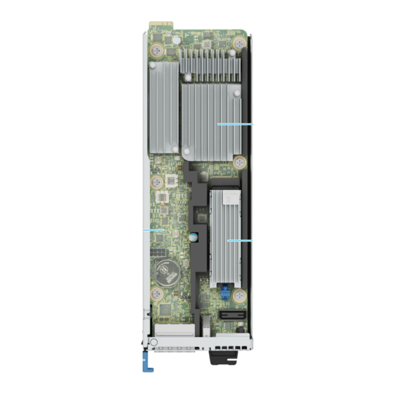
Page 8: System Configurations - Inside View For Poweredge Xr4000W
The unique Express Service Code and Service Tag are used to identify the system. The information tag is located on the rear of the system that includes system information such as iDRAC MAC address, Express Service Tag label. Dell PowerEdge XR4000w system configurations and features... - Page 9 Figure 3. Locating the Service Tag of your system 1. Information tag (bottom view) 2. MAC address information label 3. Information tag (top view) 4. Express Service Tag label Dell PowerEdge XR4000w system configurations and features...
-
Page 10: Chapter 3: Technical Specifications
• Ports and connectors specifications • Environmental specifications Sled dimensions Figure 4. Sled dimensions Table 2. PowerEdge XR4000w sled dimensions 83.25 mm (3.27 inches) 21.60 mm (0.85 inches) 250.79 mm (9.87 inches) System weight Table 3. PowerEdge XR4000w system weight... -
Page 11: Processor Specifications
The PowerEdge XR4000w system supports one USB 3.0-compliant port on the front of the system. NIC port specifications The PowerEdge XR4000w system supports 1 GbE x 2 (intel I210), RJ45 ports with LEDs on the front of the system. Serial connector specifications The PowerEdge XR4000w system supports one Micro-USB connector for RS232 serial port, which is a Micro USB on the front of the system. -
Page 12: Environmental Considerations
(NAF) with GPU Non-operating temperature range -40 to 85°C Environmental Considerations The PowerEdge XR4000w system is targeted for edge deployments and it meets all the additional standards for thermal, shock, vibration parameters. Table 6. Environmental considerations Industry... -
Page 13: Thermal Restriction Matrix
Thermal restriction matrix Table 7. M.2 Support Thermal Limitation for XR4000r Chassis (RAF Configurations) M.2 Type M.2 Module (Witness Sled) Edge 2 (Max 55°C) Edge 1 (Max 50°C) ASHRAE A4 (Max 45°C) Micron 480GB Micron 800GB Micron 960GB Micron 1.92TB Micron 3.84TB Hynix 480GB Hynix 800GB... - Page 14 Table 11. M.2 Support Thermal Limitation for XR4000z Chassis (NAF Configurations) M.2 Type M.2 Module (Witness Sled) Edge 2 (Max 55°C) Edge 1 (Max 50°C) ASHRAE A4 (Max 45°C) Micron 480GB Micron 800GB Micron 960GB Not Supported Not Supported Micron 1.92TB Micron 3.84TB Hynix 480GB Hynix 800GB...
-
Page 15: Chapter 4: Initial System Setup And Configuration
Initial system setup and configuration This section describes the tasks for initial setup and configuration of the Dell system. The section also provides general steps to set up the system and the reference guides for detailed information. Topics: • Pre-operating system management applications •... -
Page 16: Using The System
Table 13. Witness BIOS POST codes (continued) Phase POST codes DESCRIPTION 0x4F DXE IPL is started 0x60 DXE Core is started 0x61 NVRAM initialization 0x62 Installation of the South Bridge Runtime Services 0x68 PCI host bridge initialization 0x69 North Bridge DXE initialization is started 0x6A North Bridge DXE SMM initialization is started... -
Page 17: Connecting To Witness Via Serial
Connecting to Witness via serial About this task The Witness serial interface can be connected to with a USB to micro-USB cable. Figure 5. USB (left) to Micro-USB (right) cable Figure 6. USB (top) to Micro-USB (bottom) cable The micro-USB end of the cable plugs in to the micro-USB port on the front panel of the Witness. The USB end of the cable plugs into a USB port on the external system that will be communicating with the Witness. -
Page 18: Witness Serial Communication
Figure 7. USB to UART Bridge device appears when Witness is powered on The serial interface should then be accessible via serial TTY consoles such as PuTTY. Serial configuration baud rate must be set to 115200. Other settings can be left at their default value. Figure 8. -
Page 19: User Interfaces: Idrac
User interfaces: iDRAC About this task NOTE: A valid Service Tag must be programmed to the Witness and the CM must have backed up this tag as part of Witness Easy Restore (FRU recovery) process. Without a valid Service Tag, the iDRAC will not report all Witness information. - Page 20 Figure 9. iDRAC Witness landing page Initial system setup and configuration...
- Page 21 Figure 10. iDRAC system firmware inventory Figure 11. iDRAC system hardware inventory for Witness Initial system setup and configuration...
-
Page 22: User Interfaces: Redfish
Figure 12. iDRAC hardware inventory for Witness fans User interfaces: Redfish About this task For Redfish methods of Witness power control, see: Witness power operations: Redfish. Witness information can be collected through the following URI: ● /redfish/v1/Chassis/System.Integrated.1-1_System.Chassis.1-1 An example of data gathered through this URI. NOTE: Note that the variables “BMC”, “USER”, and “PASS”... -
Page 23: User Interfaces: Racadm
Figure 13. Redfish Witness information User interfaces: RACADM About this task For RACADM methods of Witness power control, see: Witness power operations: RACADM. Witness and some Chassis Manager information can be found through SW and HW operations with RACADM. Initial system setup and configuration... - Page 24 Figure 14. RACADM system chassis info Figure 15. RACADM Witness sensor information Figure 16. RACADM Witness software information Initial system setup and configuration...
- Page 25 Figure 17. RACADM Witness hardware information Initial system setup and configuration...
-
Page 26: User Interfaces: Ipmi
User interfaces: IPMI About this task IPMI control of the Witness node is limited. Please see Witness Service Tag deployment for IPMI control of the FRU. Witness host About this task Witness host interfaces are dependent on the installed host. Interfaces for the Witness host include: ●... -
Page 27: Witness Power Operations: Witness Power Button
Figure 18. Witness Node power on sequence Figure 19. Witness Node power state machine Witness power operations: Witness power button About this task The Witness Manager supports basic power button control for power-on and power-off. The ability to lock the power button through the iDRAC interface is planned but not yet supported. -
Page 28: Witness Power Button Led Behavior
Witness power button LED behavior About this task The Witness power LED is a bi-color LED consisting of AMBER and GREEN. The LED communicates Witness status during both runtime and BIOS updates. Witness power LED during runtime behavior is shown in the below table. Table 14. -
Page 29: Witness Power Operations: Redfish
Figure 20. iDRAC GUI Witness power status Figure 21. iDRAC GUI Witness power control 1 Figure 22. iDRAC GUI Witness power control 2 Witness power operations: Redfish About this task Witness power operations can be performed through the FQDN: /redfish/v1/Chassis/System.Integrated.1-1_System.Chassis.1-1/Actions/Chassis.Reset With valid actions being: ●... -
Page 30: Witness Power Operations: Racadm
-i \ --data '{ "ResetType": "ForceOff" HTTP/1.1 204 No Content Witness power operations: RACADM About this task RACADM supports the following power operations for Witness: ● powerdown ● powerup ● hardreset ● reseat ● powerstatus Figure 23. Help output for RACADM witnessnodepoweraction Witness power operations: host About this task Witness host power control capabilities are dependent on the installed host. -
Page 31: Witness Serial Communication
The Witness server utilizes a USB to UART method of serial communication accessible via a micro-USB form-factor port located on the front panel. NOTE: A valid Dell OS Agent for Witness (DOSA-W) must be installed on the Witness host for a compute sled to receive host networking information. See Witness DOSA-W deployment for more information. -
Page 32: Witness Host Network: Redfish
Figure 24. iDRAC GUI Witness network information Witness host network: Redfish About this task Witness network information can be found from the following URI: redfish/v1/Chassis/System.Integrated.1-1_System.Chassis.1-1 Example of collecting data from the above URI. Note that the variables “BMC”, “USER”, and “PASS” are set in this example. root@ubuntu:~# curl --request GET \ --url https://${BMC}/redfish/v1/Chassis/System.Integrated.1-1_System.Chassis.1-1 \ --user ${USER}:${PASS}\... -
Page 33: Witness Host Network: Racadm
Figure 25. Witness Mac1, Mac2 provided from a GET on redfish/v1/Chassis/ System.Integrated.1-1_System.Chassis.1-1 Witness host network: RACADM About this task Witness host network information through RACADM is found with the `racadm hwinventory` command. Figure 26. Witness host information through RACADM Witness host network: Witness host OS About this task Witness serial communication for details on serial connection to the Witness. -
Page 34: Using The Witness Heart Beat Function
About this task The Witness “Heart Beat” is a feature enabled through the Dell OS Agent for Witness (DOSA-W) which resides on the Witness host. Usage of the Heart Beat requires a properly deployed DOSA-W driver to the Witness host (Witness DOSA-W deployment for deployment information). - Page 35 Figure 28. Enabling the Witness Heart Beat in iDRAC The logging follows the Telco WM iDRAC behavior Spec: Table 15. Telco WM iDRAC behavior Spec Message ID Message Severity WNS0006 The Witness Server Ensure that Witness The Witness Server OS Severity -1 (Critical) Heart Beat failure is server host is booted to...
-
Page 36: Getting System Component Versions
Getting system component versions About this task Most system component versions are easily accessible through examples given in User interfaces: iDRAC. Getting component version: Witness BIOS About this task The Witness BIOS version can be found through: ● iDRAC 1. GUI 2. -
Page 37: Getting Component Version: Witness Host
Getting component version: Witness host About this task Please refer to host-specific documentation available online to determine the Witness host version. Getting component version: DOSA-W About this task Additional host-level enhancement packages potentially have their firmware reported through host-level interfaces. Getting component version: Witness host About this task Please refer to host-specific documentation available online to determine the Witness host version. -
Page 38: Updating Witness Bios: Dup (Dell Update Package)
● On completion, boot ROM locations are swapped in Witness BIOS FRU Figure 32. Witness BIOS update flow Updating Witness BIOS: DUP (Dell Update Package) About this task Witness BIOS DUPs are only supported through the iDRAC GUI or RACADM interfaces. Please follow standard iDRAC and RACADM procedures for this method. -
Page 39: Updating Witness Mcu: Dup
Figure 33. Witness MCU update flow Updating Witness MCU: DUP About this task Witness MCU BIOS DUPs are only supported through the iDRAC GUI or RACADM interfaces. Please follow standard iDRAC procedures for this method. Updating the Chassis manager About this task The chassis manager (CM) supports updates via: ●... -
Page 40: Updating Chassis Manager: Dup
● https://docs.vmware.com/en/VMware-vSphere/7.0/com.vmware.vsphere-lifecycle-manager.doc/GUID-74295A37- E8BB-4EB9-BFBA-47B78F0C570D.html Updating Witness DOSA-W About this task The Dell OS Agent for Witness supports updates via: ● In-band host-specific updates Updating Witness DOSA-W: ESXi About this task The DOSA-W update packages are provided as ESXi VIB files. Deployment of the DOSA-W on ESXi requires installation of both the DOSA-W daemon as well as the ACPI GPIO drivers. - Page 41 7. If the parameter saved shows as expected, then check the Witness IP from iDrac GUI, system, Witness sled and Witness IP should be available. Initial system setup and configuration...
-
Page 42: Chapter 5: Minimum Configuration To Post
Minimum configuration to POST The components listed below are the minimum configuration to POST: ● One XR4000w sled installed in XR4000r or XR4000z chassis ● One power supply unit Minimum configuration to POST... -
Page 43: Chapter 6: Installing And Removing System Components
Damage due to servicing that is not authorized by Dell is not covered by your warranty. Read and follow the safety instructions that are shipped with your product. -
Page 44: Recommended Tools
Recommended tools You may need any or combination of the following tools to perform the removal and installation procedures: ● Phillips 1 screwdriver ● Wrist grounding strap connected to the ground ● ESD mat You need the following tools to assemble the cables for a DC power supply unit: ●... -
Page 45: Removing The Witness Sled
Figure 35. Removing the witness sled blank from XR4000z Next steps Install a sled sled blank. Removing the witness sled Prerequisites 1. Follow the safety guidelines listed in the Safety instructions. 2. Disconnect all the peripherals and the cables from the witness sled. Steps Pull the blue tag to slide the witness sled from the chassis. -
Page 46: Installing The Witness Sled
Figure 36. Removing the witness sled from XR4000r chassis Figure 37. Removing the witness sled from XR4000z chassis Next steps Replace witness sled. Installing the witness sled Prerequisites Follow the safety guidelines listed in the Safety instructions. Installing and removing system components... - Page 47 Steps 1. Align and insert the witness sled into chassis. 2. Using the witness sled handle, slide the sled until it locks into place. NOTE: The XR4000w (witness) sled in not hot pluggable and it is recommended to power off the chassis before installing the witness sled.
-
Page 48: Installing A Sled Blank
Next steps Connect all the cables and peripherals. Installing a sled blank Prerequisites Follow the safety guidelines listed in Safety Instructions. Steps 1. Align the sled blank with the bay of the enclosure. 2. Insert and push the sled blank until the plunger locks into place. Figure 40. -
Page 49: M.2 Ssd Module
Figure 41. Installing the witness sled blank on XR4000z M.2 SSD module Removing the M.2 SSD module Prerequisites 1. Follow the safety guidelines listed in the Safety instructions. 2. Follow the procedure listed in the Before working inside your system. Steps 1. -
Page 50: Installing The M.2 Ssd Module
Figure 42. Removing the M.2 SSD module Next steps Replace the M.2 SSD module. Installing the M.2 SSD module Prerequisites 1. Follow the safety guidelines listed in the Safety instructions. 2. Follow the procedure listed in the Before working inside your system. -
Page 51: System Battery
Figure 43. Installing the M.2 SSD module Next steps Follow the procedure listed in After working inside your system. System battery This is a service technician replaceable part only. Replacing the system battery Prerequisites WARNING: There is a danger of a new battery exploding if it is incorrectly installed. Replace the battery only with the same or equivalent type recommended by the manufacturer. - Page 52 Figure 44. Removing the system battery CAUTION: To avoid damage to the battery connector, you must firmly support the connector while installing or removing a battery. 2. To install a new system battery: a. Hold the battery with the positive side facing up and slide it under the securing tabs. b.
-
Page 53: System Board
Figure 45. Installing the system battery System board This is a service technician replaceable part only. Removing the system board Prerequisites 1. Follow the safety guidelines listed in the Safety instructions. 2. Follow the procedure listed in the Before working inside your system. -
Page 54: Installing System Board
Figure 46. Removing the system board Next steps Install the system board. Installing system board Prerequisites NOTE: Before replacing the system board, replace the old iDRAC MAC address label in the Information tag with the iDRAC MAC address label of the replacement system board. 1. - Page 55 Figure 47. Installing the system board Next steps 1. Replace the M.2 SSD module. Installing and removing system components...
-
Page 56: Chapter 7: Recovering The Witness Bios
Recovering the Witness BIOS About this task Witness BIOS can be recovered via: ● Witness BIOS DUP flash ● SPI flashing the EEPROM chips Witness BIOS does not have any software-based recovery procedures. As the Witness platform has 2 BIOS EEPROMs, failure to flash a BIOS to one EEPROM will result in that ROM not being activated by the CM –... -
Page 57: Chapter 8: Recovering Witness Bios: Dup Flashing
Recovering Witness BIOS: DUP flashing About this task As the Witness board contains two SPI EEPROM BIOS chips that are mixed by the chassis manager (CM), a corrupt BIOS on the active chip should be a recoverable situation. The assumptions here are that: 1. -
Page 58: Chapter 9: Recovering The Witness Host Os
The RASR tool developed by the FEAR (Factory Enablement And Recovery) team can reimage a Witness host operating system along with any required drivers or packages. These packages include: ● Dell OS-Agent for Witness (DOSA-W) ○ Additional GPIO driver support packages ●... -
Page 59: Rasriso To Rasrusb Tool Instructions
Follow the steps to create a RASRUSB key from RASR ISO file. Extract the ISO image 1. Go to dell.com/support, enter XR4000w Witness sled service tag. 2. Download RASRISOtoUSB.zip from drivers and downloads section on the XR4000w support page. 3. Extract the RASRISOtoUSB.zip file. - Page 60 Figure 49. Extracted files 2. Copy RASR ISO file to the iso directory after extraction is complete. NOTE: The RASR ISO file is copied to the iso directory after extracting the RASRISOtoUSB.zip file. Figure 50. RASRISO.iso files Launch executable Right click on "rasrisotorasrusb.exe" and run as administrator. Recovering the Witness host OS...
- Page 61 Figure 51. Launch executable Select USB device 1. Ensure that the USB device is plugged in. Select the USB device and press enter. Figure 52. Selecting USB device 2. Confirm selection, and press enter. NOTE: USB device will be wiped after this step. Back up any important data in the USB before proceeding. Recovering the Witness host OS...
- Page 62 Select RASRISO 1. Select the RASRISO to use and press enter. Figure 53. Selecting RASRISO 2. The contents of ISO are now being extracted to the USB device, this may take few minutes. Wait until extraction is complete. Recovering the Witness host OS...
- Page 63 Figure 54. Extracting iso contents to USB Confirm completion 1. Once extraction is complete, the following message is displayed, "Successfully created RASRUSB, please eject USB device visa Windows Eject Tool before removing physical USB, press enter to exit:" 2. Rerun iso extraction if the process fails. Eject USB Eject USB device to ensure the files do not get corrupted before physically disconnecting USB.
- Page 64 Figure 55. Ejecting USB Recovering the Witness host OS...
-
Page 65: Chapter 10: Minimum Configuration To Post
Minimum configuration to POST The components listed below are the minimum configuration to POST: ● One XR4000w sled installed in XR4000r or XR4000z chassis ● One power supply unit Minimum configuration to POST... -
Page 66: Chapter 11: Witness Does Not Power On
Witness does not power on About this task Items to check: 1. Witness power LED does not turn on a. Use Witness power control: CPLD to clear the CPLD power request byte b. After clearing CPLD request byte, use Witness power operations to power on Witness 2. -
Page 67: Chapter 12: Witness Does Not Have Serial Output
Witness does not have serial output About this task Items to check: 1. Witness is not powered on a. Use Witness power operations. 2. Improper serial connection a. Use Connecting to Witness via serial. 3. Witness is booting a. Serial output will appear to hang at several locations in the Witness boot process. Simply give the system enough time to fully-boot. -
Page 68: Chapter 13: Witness Information Does Not Appear In Idrac
Witness information does not appear in iDRAC About this task Witness IP is not reported NOTE: Witness IP does not require a valid Service Tag to populate in iDRAC front-end. Items to check: 1. Witness NIC 1 is improperly connected to a configured network a. -
Page 69: Chapter 14: Witness Service Tag, Eppid, Mac Information Not Reported
Witness Service Tag, EPPID, MAC information not reported About this task Witness Service Tag, EPPID, and MAC information require a valid Witness Service Tag to populate in iDRAC front-end. Items to check: 1. Valid Service Tag in compute sled CPLD a. -
Page 70: Chapter 15: Chassis Manager, Witness Mcu, Or Witness Bios Dups Failing
Chassis Manager, Witness MCU, or Witness BIOS DUPs failing About this task NOTE: Witness BIOS DUPs should be expected to run anywhere from 45-90 minutes before completion. 1. Attempting to install incompatible firmware 2. iDRAC job queue task immediately “Failed” or stuck in “Scheduling (0%)” a. -
Page 71: Chapter 16: Jumpers And Connectors
Jumpers and connectors This topic provides some basic and specific information about jumpers and switches. It also describes the connectors on the various boards in the system. Jumpers on the system board help to disable the system and reset the passwords. To install components and cables correctly, you must know the connectors on the system board. -
Page 72: Dip Switch Settings
Damage due to servicing that is not authorized by Dell is not covered by your warranty. Read and follow the safety instructions that are shipped with your product. - Page 73 3. Insert compute sled into chassis and power on the compute sled. 4. Power off the compute sled and remove the compute sled from chassis. 5. Move the DIP switch on the system board from switches 2 and 3 to switches 1 and 2. 6.
-
Page 74: Chapter 17: Getting Help
Dell contact information on your purchase invoice, packing slip, bill or Dell product catalog. The availability of services varies depending on the country and product, and some services may not be available in your area. To contact Dell for sales, technical... -
Page 75: Quick Resource Locator For Poweredge Xr4000W System
Dell. This information is used by Dell Technical Support to troubleshoot the issue. ● Proactive contact — A Dell Technical Support agent contacts you about the support case and helps you resolve the issue. The available benefits vary depending on the Dell Service entitlement purchased for your device. For more information about SupportAssist, go to www.dell.com/supportassist. -
Page 76: Chapter 18: Documentation Resources
This section provides information about the documentation resources for your system. To view the document that is listed in the documentation resources table: ● From the Dell support site: 1. Click the documentation link that is provided in the Location column in the table. - Page 77 Table 17. Additional documentation resources for your system (continued) Task Document Location Managing your system For information about systems management www.dell.com/poweredgemanuals software offered by Dell, see the Dell OpenManage Systems Management Overview Guide. For information about setting up, using, www.dell.com/openmanagemanuals > and troubleshooting OpenManage, see the OpenManage Server Administrator Dell OpenManage Server Administrator User’s...