Table of Contents
Advertisement
Quick Links
Advertisement
Table of Contents

Related Manuals for Dell PowerEdge XR4510c


Summary of Contents for Dell PowerEdge XR4510c
- Page 1 Dell PowerEdge XR4510c Installation and Service Manual December 2022 Rev. A00...
- Page 2 A WARNING indicates a potential for property damage, personal injury, or death. © 2022 Dell Inc. or its subsidiaries. All rights reserved. Dell Technologies, Dell, and other trademarks are trademarks of Dell Inc. or its subsidiaries. Other trademarks may be trademarks of their respective owners.
-
Page 3: Table Of Contents
Contents Chapter 1: About this document....................6 Chapter 2: Dell PowerEdge XR4510c system configurations and features ........7 System configurations - front view for PowerEdge XR4510c..................7 System configurations - rear view for PowerEdge XR4510c................... 9 System configurations - inside view for PowerEdge XR4510c................10 NIC indicator codes................................ - Page 4 System BIOS.................................29 iDRAC Settings................................44 Device Settings................................45 Dell Lifecycle Controller..............................45 Embedded system management..........................45 Boot Manager..................................45 PXE boot..................................... 45 Chapter 7: Minimum configuration to POST ................46 Chapter 8: Installing and removing system components.............. 47 Safety instructions................................47 Before working inside your system ..........................47 After working inside your system..........................
- Page 5 Chapter 11: Using system diagnostics..................81 Dell Embedded System Diagnostics..........................81 Running the Embedded System Diagnostics from Boot Manager..............81 Running the Embedded System Diagnostics from the Dell Lifecycle Controller.......... 81 System diagnostic controls............................82 Chapter 12: Getting help......................83 Recycling or End-of-Life service information......................83...
-
Page 6: Chapter 1: About This Document
About this document This document provides an overview about the system, information about installing and replacing components, diagnostic tools, and guidelines to be followed while installing certain components. About this document... -
Page 7: Chapter 2: Dell Poweredge Xr4510C System Configurations And Features
Dell PowerEdge XR4510c system configurations and features The PowerEdge XR4510c system is a 1U half-width, 1-processor server sled that supports: ● One 3 Generation Intel Xeon D Scalable processor with up to 20 cores ● Four DDR4 DIMM slots ● Up to 4 x M.2 NVMe SSDs Topics: •... - Page 8 XR4000z chassis, the power button LED indicator status may be delayed for up to two minutes while the sled is initializing. The power button LED will start slowly blinking to indicate the system is performing Dell PowerEdge XR4510c system configurations and features...
-
Page 9: System Configurations - Rear View For Poweredge Xr4510C
Bezel will have filter with pressure sensitive sensor to indicate when replacement is needed. System configurations - rear view for PowerEdge XR4510c Figure 2. Rear view for PowerEdge XR4510c Table 2. Features available on the rear view Item Ports, panels, or slots Icon Description... -
Page 10: System Configurations - Inside View For Poweredge Xr4510C
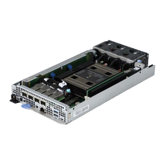
System configurations - inside view for PowerEdge XR4510c Figure 3. Inside view of the PowerEdge XR4510c sled 1. Connector cover 2. Fan bracket 3. System board 4. Processor 5. Network I/O ports 6. Sled handle 7. Information Tag 8. M.2 Riser Module 9. -
Page 11: Nic Indicator Codes
The unique Express Service Code and Service Tag are used to identify the system. The information tag is located on the rear of the system that includes system information such as iDRAC MAC address, Express Service Tag label. Dell PowerEdge XR4510c system configurations and features... -
Page 12: System Information Label
Alternatively, the Service Tag information is located on a label on the left wall of the chassis. System information label The system information label is located on the back of the system cover. Figure 6. DIP switch information Dell PowerEdge XR4510c system configurations and features... - Page 13 Figure 7. Mechanical overview and ports information Dell PowerEdge XR4510c system configurations and features...
-
Page 14: Chapter 3: Technical Specifications
• Ports and connectors specifications • Video specifications • Environmental specifications Sled dimensions Figure 8. Sled dimensions Table 4. PowerEdge XR4510c sled dimensions Z (handle closed) 167.2 mm (6.58 inches) 41.25 mm (1.62 inches) 342.5 mm (13.48 inches) Technical specifications... -
Page 15: System Weight
Number of processors supported Generation Intel Xeon D Scalable processor with up to 20 cores Cooling fan specifications The PowerEdge XR4510c system supports up to three standard cabled fans with normal and reverse air-flow. Table 7. Cooling fan specifications Fan type Label color... -
Page 16: Memory Specifications
The PowerEdge XR4510c system supports Boot Optimized Storage Subsystem (BOSS-N1): 2 x M.2 SSDs as internal boot. Drives The PowerEdge XR4510c system supports up to 4 x M.2 SSDs (M.2 2280 and M.2 22110) installed on M.2 riser module. Ports and connectors specifications USB ports specifications Table 10. -
Page 17: Serial Connector Specifications
The PowerEdge XR4510c system supports one Mini-DisplayPort in front of the system. iDRAC9 port specifications The PowerEdge XR4510c system supports one RJ45 with port status LEDs for iDRAC remote management (dedicated port only) on front of the system. Video specifications The PowerEdge XR4510c system supports integrated Matrox G200 graphics controller embedded in the iDRAC(BMC) chip, with 16 MB of video frame buffer. -
Page 18: Environmental Considerations
-5 to 55°C with a startup temperature of 0°C Non-operating temperature range -40 to 85°C Environmental Considerations The PowerEdge XR4510c system is targeted for edge deployments and it meets all the additional standards for thermal, shock, vibration parameters. Table 14. Environmental considerations Industry... -
Page 19: Thermal Restriction Matrix
Thermal restriction matrix Table 15. XR4000r RAF Configuration Matrix RAF Configurations CPU Type HSK type Fan type Edge 2 (Max Edge 1 (Max ASHRAE A4 (Max 55°C) 50°C) 45°C) Intel® Xeon® D - 2796NT, 20C,120W Intel® Xeon® D - 2776NT,16C,117W Vaper Standard Intel®... - Page 20 Table 18. M.2 Support Thermal Limitation for XR4000z Chassis (RAF Configurations) Riser Module BOSS Module AIC Card Type Edge 2 Edge 1 ASHRAE A4 Edge 2 Edge 1 ASHRAE Edge 2 Edge 1 ASHRAE (Max (Max (Max 45°C) (Max (Max A4 (Max (Max (Max...
- Page 21 Table 20. M.2 Support Thermal Limitation for XR4000r Chassis (RAF Configurations) (continued) Riser Module BOSS Module AIC Card Type Edge 2 Edge 1 ASHRAE A4 Edge 2 Edge 1 ASHRAE Edge 2 Edge 1 ASHRAE (Max (Max (Max 45°C) (Max (Max A4 (Max (Max...
- Page 22 ● Micron M.2 with 3.84BT on AIC card has active throttling for thermal protection when fully loaded and at 55°C environment temperature. ● In redundant mode, two power supplies are required. A single power supply failure is not supported. ● If memory slots are not fully populated, dummy DIMMs are required. ASHRAE A4 Support Restriction for NAF (Normal Air Flow Direction) Configurations: ●...
-
Page 23: Chapter 4: Initial System Setup And Configuration
Initial system setup and configuration This section describes the tasks for initial setup and configuration of the Dell system. The section also provides general steps to set up the system and the reference guides for detailed information. Topics: • Setting up the system •... -
Page 24: Options To Log In To Idrac
Ensure that you change the default username and password after setting up the iDRAC IP address. For more information about logging in to the iDRAC and iDRAC licenses, see the latest Integrated Dell Remote Access Controller User's Guide at www.dell.com/idracmanuals. -
Page 25: Options To Download Drivers And Firmware
You can also access iDRAC using command-line protocol - RACADM. For more information, see the Integrated Dell Remote Access Controller RACADM CLI Guide available at https://www.dell.com/idracmanuals. You can also access iDRAC using automation tool - Redfish API. For more information, see the Integrated Dell Remote Access Controller User's Guide Redfish API Guide available at https://developer.dell.com. -
Page 26: Chapter 5: Resources To Install Operating System
Dell Lifecycle Controller User's Guide, go to https://www.dell.com/poweredgemanuals > Product Support page of your system > Documentation. Dell recommends using Lifecycle Controller to install the OS, since all required drivers are installed on the system. NOTE: To determine the most recent iDRAC release for your platform and for latest documentation version, see KB article at https://www.dell.com/support/article/sln308699. -
Page 27: Downloading Drivers And Firmware
Ensure that you clear the web browser cache before downloading the drivers and firmware. Steps 1. Go to www.dell.com/support/drivers. 2. Enter the Service Tag of the system in the Enter a Dell Service Tag, Dell EMC Product ID or Model field, and then press Enter. NOTE: If you do not have the Service Tag, click Browse all products, and navigate to your product. -
Page 28: Chapter 6: Pre-Operating System Management Applications
UEFI (Unified Extensible Firmware Interface). You can enable or disable various iDRAC parameters by using the iDRAC settings utility. For more information about this utility, see Integrated Dell Remote Access Controller User’s Guide at www.dell.com/ poweredgemanuals. -
Page 29: System Bios
Table 25. System Setup Main Menu (continued) Option Description Device Settings Enables you to configure device settings for devices such as storage controllers or network cards. Service Tag Settings Enables you to configure the System Service Tag. System BIOS To view the System BIOS screen, power on the system, press F2, and click System Setup Main Menu > System BIOS. Table 26. - Page 30 Table 27. System Information details (continued) Option Description System Manufacturer Contact Information Specifies the contact information of the system manufacturer. System CPLD Version Specifies the current version of the system Complex Programmable Logic Device (CPLD) firmware. UEFI Compliance Version Specifies the UEFI compliance level of the system firmware. Memory Settings To view the Memory Settings screen, power on the system, press F2, and click System Setup Main Menu >...
- Page 31 MADT Core Enumeration Specifies the MADT Core Enumeration. This option is set to default in Round Robin. Linear option supports industry core enumeration whereas, Round Robin option supports Dell optimized core enumeration. UPI Prefetch Enables you to get the memory read started early on DDR bus.
- Page 32 Enables or disables AVX ICCP Pre-Grant License. This option is set to Disabled by default. Dell Controlled Turbo Dell Controlled Turbo Settings Controls the turbo engagement. Enable this option only when System Profile is set to Performance or Custom, and CPU Power Management is set to Performance.
- Page 33 Enables or disables the boot mode. The option is set to Non-RAID mode by default. BIOS NVMe Driver Sets the drive type to boot the NVMe driver. The available options are Dell Qualified Drives and All Drives. This option is set to Dell Qualified Drives by default.
- Page 34 Operating systems must be UEFI-compatible to be installed from the UEFI boot mode. DOS and 32-bit operating systems do not support UEFI and can only be installed from the BIOS boot mode. NOTE: For the latest information about supported operating systems, go to www.dell.com/ossupport. Pre-operating system management applications...
- Page 35 Changing boot order About this task You may have to change the boot order if you want to boot from a USB key or an optical drive. The following instructions may vary if you have selected BIOS for Boot Mode. NOTE: Changing the drive boot sequence is only supported in BIOS boot mode.
- Page 36 Table 36. ISCSI Device1 Settings screen details (continued) Option Description Connection 2 Enables or disables the iSCSI connection. This option is set to Disabled by default. Connection 1 Settings Enables you to control the configuration for the iSCSI connection. Connection 2 Settings Enables you to control the configuration for the iSCSI connection.
- Page 37 To view the Serial Communication screen, power on the system, press F2, and click System Setup Main Menu > System BIOS > Serial Communication. NOTE: The serial port is optional for the PowerEdge XR4510c system. The Serial Communication option is applicable only if the serial COM port is installed in the system. Table 38. Serial Communication details...
- Page 38 Table 38. Serial Communication details (continued) Option Description The options available for System without serial COM port (DB9) are On without Console Redirection, On with Console Redirection, Off. This option is set to Off by default. The options available for System with serial COM port (DB9) are On without Console Redirection, On with Console Redirection via Com1, On with Console Redirection via Com2,...
- Page 39 Table 39. System Profile Settings details Option Description System Profile Sets the system profile. If you set the System Profile option to a mode other than Custom, the BIOS automatically sets the rest of the options. You can only change the rest of the options if the mode is set to Custom.
- Page 40 Table 40. System Security details Option Description CPU AES-NI Improves the speed of applications by performing encryption and decryption by using the Advanced Encryption Standard Instruction Set (AES-NI). This option is set to Enabled by default. System Password Sets the system password. This option is read-only if the password jumper is not installed in the system.
- Page 41 Table 42. System Security details (continued) Option Description Power Button Enables or disables the power button on the front of the system. This option is set to Enabled by default. AC Power Recovery Sets how the system behaves after AC power is restored to the system. This option is set to Last by default.
- Page 42 Table 42. System Security details (continued) Option Description Secure Boot Policy Summary Specifies the list of certificates and hashes that secure boot uses to authenticate images. Creating a system and setup password Prerequisites Ensure that the password jumper is enabled. The password jumper enables or disables the system password and setup password features.
- Page 43 Deleting or changing system and setup password Prerequisites NOTE: You cannot delete or change an existing system or setup password if the Password Status is set to Locked. Steps 1. To enter System Setup, press F2 immediately after turning on or restarting your system. 2.
-
Page 44: Idrac Settings
NOTE: Accessing some of the features on the iDRAC settings needs the iDRAC Enterprise License upgrade. For more information about using iDRAC, see Dell Integrated Dell Remote Access Controller User's Guide at https:// www.dell.com/idracmanuals. -
Page 45: Device Settings
Dell Lifecycle Controller Dell Lifecycle Controller (LC) provides advanced embedded systems management capabilities including system deployment, configuration, update, maintenance, and diagnosis. LC is delivered as part of the iDRAC out-of-band solution and Dell system embedded Unified Extensible Firmware Interface (UEFI) applications. -
Page 46: Chapter 7: Minimum Configuration To Post
Minimum configuration to POST The components listed below are the minimum configuration to POST: ● One memory module (DIMM) ● One power supply unit ● XR4000r or XR4000z chassis (Power Interposer Board, cables) ● System board ● XR4510c sled Minimum configuration to POST... -
Page 47: Chapter 8: Installing And Removing System Components
Damage due to servicing that is not authorized by Dell is not covered by your warranty. Read and follow the safety instructions that are shipped with your product. -
Page 48: After Working Inside Your System
After working inside your system Prerequisites Follow the safety guidelines listed in Safety instructions. Steps 1. Replace the system cover. 2. If applicable, remove the I/O connector cover from the system connectors. Install the sled into the enclosure. 3. Reconnect the peripherals and connect the system to the electrical outlet, and then power on the system. Recommended tools You may need any or combination of the following tools to perform the removal and installation procedures: ●... -
Page 49: Installing A Sled Blank
Figure 9. Removing a sled blank from XR4000r Figure 10. Removing the sled blank from XR4000z Next steps Install a sled a sled blank. Installing a sled blank Prerequisites Follow the safety guidelines listed in Safety instructions. Installing and removing system components... -
Page 50: Removing The Sled
Steps 1. Align the sled blank with the bay of the chassis. 2. Insert and push the sled blank, until it locks into place. Figure 11. Installing a sled blank on XR4000r Figure 12. Installing the sled blank on XR4000z Removing the sled Prerequisites Follow the safety guidelines listed in... - Page 51 Steps 1. Pull the blue lever on the sled to release the sled handle. 2. Holding the sled handle, slide the sled out of the enclosure. NOTE: The numbers on the image do not depict the exact steps. The numbers are for representation of sequence. CAUTION: Support the system with both hands while sliding it out of the enclosure.
-
Page 52: Installing The Sled
Next steps Installing the sled Installing the sled Prerequisites Follow the safety guidelines listed in Safety instructions. Steps 1. Pull the blue lever on the sled to free the sled handle. 2. Holding the sled with both hands, align the sled along the sled-bay in to the enclosure. 3. -
Page 53: Sled Cover
Figure 16. Installing the sled into XR4000z Sled cover Removing the sled cover Prerequisites 1. Follow the safety guidelines listed in the Safety instructions. 2. Power off the sled, and any attached peripherals. 3. Follow the steps for Removing a sled. -
Page 54: Installing The Sled Cover
Figure 17. Removing the sled cover Next steps Follow the procedure listed in Replace the sled cover. Installing the sled cover Prerequisites 1. Follow the safety guidelines listed in the Safety instructions. 2. Ensure that all internal cables are connected and routed properly, and no tools or extra parts are left inside the system. Steps 1. -
Page 55: Cooling Fans
Next steps Follow the procedure listed in After working inside your system. Cooling fans Removing a cooling fan Prerequisites 1. Follow the safety guidelines listed in Safety instructions. 2. Follow the procedure listed in Before working inside your system. Remove the sled. -
Page 56: Installing A Cooling Fan
Installing a cooling fan Prerequisites 1. Follow the safety guidelines listed in Safety Instructions. 2. Follow the procedure listed in Before working inside your system. Remove the sled. Steps 1. Pull the blue latch on the side of the fan module and lift the fan handle. 2. -
Page 57: System Memory
System memory System memory guidelines The PowerEdge XR4510c system supports DDR4 registered DIMMs (RDIMMs) and LRDIMMs. System memory holds the instructions that are executed by the processor. Your system contains 4 memory sockets organized into 4 channels to the processor. -
Page 58: General Memory Module Installation Guidelines
NOTE: The memory bus operates at 2933 MT/s depending on the factors described in the General memory module installation guidelines. General memory module installation guidelines To ensure optimal performance of your system, observe the following general guidelines when configuring your system memory. If your system's memory configurations fail to observe these guidelines, your system might not boot, stop responding during memory configuration, or operate with reduced memory. -
Page 59: Installing A Memory Module
3. Lift the memory module away from the system. Figure 22. Removing a memory module Next steps Installing the memory module. 2. If you are removing the memory module permanently, install a memory module blank. The procedure to install a memory module blank is similar to that of the memory module. -
Page 60: Boss-N1 Card
3. Press the memory module with your thumbs until the ejectors firmly click into place. When the memory module is properly seated in the socket, the levers on the memory module socket align with the levers on the other sockets that have memory modules installed. -
Page 61: Installing The Boss-N1 Card
Figure 24. Removing the BOSS-N1 card Next steps Replace the BOSS-N1 card Replace the M.2 SSD module Installing the BOSS-N1 card Prerequisites 1. Follow the safety guidelines listed in the Safety instructions. 2. Follow the procedure listed in Before working inside your system. -
Page 62: Removing The M.2 Ssd Module
Figure 25. Installing the BOSS-N1 card Next steps After working inside your system. Removing the M.2 SSD module Prerequisites 1. Follow the safety guidelines listed in Safety instructions. 2. Follow the procedure listed in Before working inside your system. Remove the BOSS-N1 card. -
Page 63: Installing The M.2 Ssd Module
Installing the M.2 SSD module Prerequisites 1. Follow the safety guidelines listed in Safety instructions. 2. Follow the procedure listed in Before working inside your system. Steps 1. Align the M.2 SSD module connector with the connectors on the BOSS-N1 card. 2. -
Page 64: Installing The M.2 Riser Module
Figure 28. Removing the M.2 riser Next steps Replace the M.2 Riser. Installing the M.2 riser module Prerequisites 1. Follow the safety guidelines listed in Safety instructions. 2. Follow the procedure listed in Before working inside your system. Steps 1. Align the M.2 module with the system board and insert it firmly using the blue touch point until the riser is fully seated in the slot. -
Page 65: Removing The M.2 Ssd Module From The M.2 Riser Module
Next steps Follow the procedure listed in After working inside your system. Removing the M.2 SSD module from the M.2 riser module Prerequisites 1. Follow the safety guidelines listed in Safety instructions. 2. Follow the procedure listed in Before working inside your system. -
Page 66: Network I/O Board
Figure 31. Installing the M.2 SSD module Next steps Installing the M.2 riser module. 2. Follow the procedure listed in the After working inside your system. Network I/O board Removing the Network I/O board Prerequisites 1. Follow the safety guidelines listed in Safety instructions. -
Page 67: Install The Network I/O Board
Figure 32. Removing the Network I/O Board Figure 33. Cable routing for Network I/O Board Next steps Installing the Network I/O Board Install the Network I/O Board Prerequisites 1. Follow the safety guidelines listed in Safety instructions. 2. Follow the procedure listed in Before working inside your system. -
Page 68: System Battery
Figure 34. Install the Network I/O board 4. Using the Phillips 2 screwdriver, tighten the blue thumbscrew on the Network I/O Board and ensure it is installed correctly. CAUTION: Follow the guiding pin to prevent damage to the Network I/O board. NOTE: The numbers on the image do not depict the exact steps. - Page 69 Figure 35. Removing the system battery CAUTION: To avoid damage to the battery connector, you must firmly support the connector while installing or removing a battery. 2. To install a new system battery: a. Push the battery holder clip away. NOTE: Ensure that the + side of the battery is facing the battery holder clip.
-
Page 70: System Board
Figure 36. Installing the system battery Next steps 1. Follow the procedure listed in the After working inside your system. 2. Confirm that the battery is operating properly, by performing the following steps: a. Enter the System Setup, while booting, by pressing F2. b. - Page 71 Memory modules M.2 BOSS card M.2 Riser card Network I/O Board g. Disconnect all cables from the system board. CAUTION: Take care not to damage the system identification button while removing the system board from the system. Steps 1. Using a Phillips 2 screwdriver, remove the two screws that secure the connector cover on the system board to the chassis. Figure 37.
-
Page 72: Installing The System Board
Figure 38. Removing the system board Next steps Installing the system board. Installing the system board Prerequisites NOTE: Before replacing the system board, replace the old iDRAC MAC address label in the Information tag with the iDRAC MAC address label of the replacement system board 1. - Page 73 Figure 39. Installing the system board 5. Using a Phillips 2 screwdriver, tighten the screws that secure the connector cover to the system board. Figure 40. Installing the connector cover Next steps 1. Replace the following components: Trusted platform module (TPM).
- Page 74 Upgrading the Trusted Platform Module section. 4. If you are not using Easy Restore, import your new or existing iDRAC Enterprise license. For more information, see the Integrated Dell Remote Access Controller User's Guide available at https://www.dell.com/idracmanuals 5. Follow the procedure listed in After working inside your system.
-
Page 75: Trusted Platform Module
Trusted Platform Module This is a service technician replaceable part only. Upgrading the Trusted Platform Module Removing the TPM Prerequisites NOTE: ● Ensure the operating system is compatible with the TPM version you are installing. ● Ensure that you download and install the latest BIOS firmware on your system. ●... -
Page 76: Initializing Tpm For Users
Figure 41. Installing the TPM Initializing TPM for users Steps 1. Initialize the TPM. For more information, see Initializing the TPM for users. 2. The TPM Status changes to Enabled, Activated. Initializing the TPM 2.0 for users Steps 1. While booting your system, press F2 to enter System Setup. 2. -
Page 77: Chapter 9: Upgrade Kits
Upgrade Kits The table lists the available After Point Of Sale [APOS] kits. Table 49. Upgrade kits Kits Related links to service instructions Trusted Platform Module (TPM) Installing the TPM M.2 SSDs Installing the M.2 SSD module on M.2 riser Network I/O Board Installing the Network I/O Board Storage controller cards... -
Page 78: Chapter 10: Dip Switches
DIP Switches This topic provides some basic and specific information about DIP switches. DIP switches on the system board help to disable the system and reset the passwords. To set the switches correctly, you must know the location on the system board. Topics: •... -
Page 79: System Board Jumper Dip Switch Settings
Damage due to servicing that is not authorized by Dell is not covered by your warranty. Read and follow the safety instructions that are shipped with your product. - Page 80 Steps 1. Power off the compute sled and remove the compute sled from chassis. 2. Move the DIP switch on the system board from switches 1 and 2 to switches 2 and 3. NOTE: Use a plastic scribe to change the DIP switch settings. NOTE: The existing passwords are not disabled (erased) until the system boots with the DIP switch on switches 2 and 3.
-
Page 81: Chapter 11: Using System Diagnostics
Using system diagnostics If you experience an issue with the system, run the system diagnostics before contacting Dell for technical assistance. The purpose of running system diagnostics is to test the system hardware without using additional equipment or risking data loss. -
Page 82: System Diagnostic Controls
System diagnostic controls Table 51. System diagnostic controls Menu Description Configuration Displays the configuration and status information of all detected devices. Results Displays the results of all tests that are run. System health Provides the current overview of the system performance. Event log Displays a time-stamped log of the results of all tests run on the system. -
Page 83: Chapter 12: Getting Help
Dell contact information on your purchase invoice, packing slip, bill or Dell product catalog. The availability of services varies depending on the country and product, and some services may not be available in your area. To contact Dell for sales, technical... -
Page 84: Quick Resource Locator For Poweredge Xr4510C System
Dell. This information is used by Dell Technical Support to troubleshoot the issue. ● Proactive contact — A Dell Technical Support agent contacts you about the support case and helps you resolve the issue. The available benefits vary depending on the Dell Service entitlement purchased for your device. For more information about SupportAssist, go to www.dell.com/supportassist. -
Page 85: Chapter 13: Documentation Resources
This section provides information about the documentation resources for your system. To view the document that is listed in the documentation resources table: ● From the Dell support site: 1. Click the documentation link that is provided in the Location column in the table. - Page 86 Table 52. Additional documentation resources for your system (continued) Task Document Location Managing your system For information about systems management www.dell.com/poweredgemanuals software offered by Dell, see the Dell OpenManage Systems Management Overview Guide. For information about setting up, using, www.dell.com/openmanagemanuals > and troubleshooting OpenManage, see the OpenManage Server Administrator Dell OpenManage Server Administrator User’s...