Table of Contents
Advertisement
Quick Links
Advertisement
Table of Contents

Related Manuals for Emerson DIXELL XD70T


Summary of Contents for Emerson DIXELL XD70T
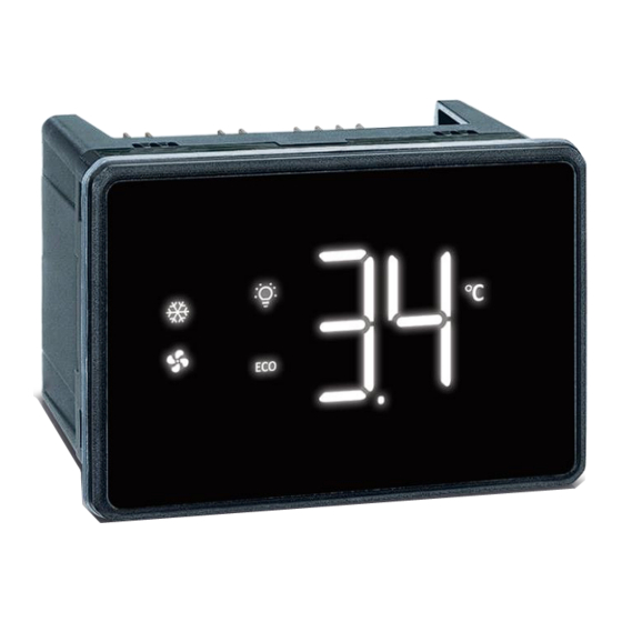
- Page 1 Full Touch XD70T (V.1.0)
-
Page 2: Table Of Contents
INDEX IMPORTANT USER INFORMATION ..................................4 PRODUCT DISPOSAL (WEEE) ....................................5 GENERALITIES ........................................6 USER INTERFACE ........................................6 SCREENS ........................................6 ICONS ........................................... 7 GESTURES ........................................9 HOME BROWSING ......................................9 STAND-BY MODE ......................................9 PROGRAMMING MENU ....................................9 SETPOINT MENU ......................................10 HOTKEY –... - Page 3 14.6.3 GENERAL NOTES ....................................40 14.7 DEAD BAND REGULATION ( ) ................................40 14.8 ON/OFF OUTPUT ( F) ..................................40 14.9 ENERGY SAVING OUTPUT ( = HES) ................................ 41 14.10 CONDENSER FAN OUTPUT ( ) ............................... 41 14.11 SECOND COMPRESSOR OUTPUT ( = CP2) ..............................
-
Page 4: Important User Information
1. IMPORTANT USER INFORMATION • symbol is intended to alert the user of a non-insultated voltage source within the product area that is sufficiently high to constitute a risk of electric shock to persons. • symbol is intended to alert the user of important operating and maintenance (servicing) instructions. -
Page 5: Product Disposal (Weee)
• It is good practice to bear in mind the following indications for all Dixell products: Prevent the electronic circuits from getting wet as contact made with water, humidity or any other type of liquid can damage them. Comply with the temperature and humidity limits specified in the manual in order to store the product correctly. -
Page 6: Generalities
3. GENERALITIES The XD-T is a microprocessor-based controller suitable for applications on medium or low temperature ventilated refrigeration units. It has 5 relay outputs to control compressor, fans, light and defrost or auxiliary outputs. The device is also provided with up to 4 NTC, PTC or PT1000 probe inputs. There are up to 3 configurable digital inputs. -
Page 7: Icons
Parameter Menu: These screens enable the modification of all parameter values. Stand-By: in this condition all outputs are deactivated. HotKey Download: “PRG” blinks during download operations (copy from HotKey to the internal memory) HotKey Upload: “PRG” blinks during upload operations (copy from internal memory to the HotKey) X9: it is possible to create the label of the parameter to be visualized or modified. - Page 8 FLASH When in the Virtual Keyboard screen: pull down ON When in the Virtual Keyboard screen: pull down OFF No alarm is active ALARM FLASH Some alarm is active Not used Celsius Degree FLASH Not used Measurement units: Celsius degree Not used Fahrenheit Degree FLASH...
-
Page 9: Gestures
4.3 GESTURES GESTURE NAME HOW-TO DESCRIPTION Switch ON / Switch OFF: when in Virtual Press a specific area Keyboard, use this to turn on/off a specific ONE TAP of the screen with a function. When in Programming mode, use this to finger for 1 sec select a parameter or a parameter value. -
Page 10: Setpoint Menu
4.7 SETPOINT MENU When in Programming Menu, it is possible to enter the Setpoint Menu by touching the SET icon for 3 sec. Both SET and PRG icons will blink until the Setpoint Menu is unlocked. Both PROG LEVEL icons start toggling to indicate that the visualized value is editable. -
Page 11: Parameter Menu
For example, if a modification of the “interval between defrosts” parameters is required (label “idF”), these are the steps to follow: Enter the X9 screen Swipe-up or down the first char position (lower segment on the left) until char “i” (lowercase) appears Move to the second char position (segment in the middle) and swipe-up or down until char “d”... -
Page 12: Password Menu
Alarm configuration parameters Digital and analogue output configuration parameters Digital input configuration parameters Energy saving configuration parameters Counters, read only values Real Time Clock configuration parameters Memory storage management Serial Communication port configuration parameters User Interface configuration parameters Information, read only parameters Password for entering protected menu parameters 4.12 PASSWORD MENU When in the PAS group, it is possible to set the password value by touching the PRG icon for 3 sec. -
Page 13: Probe Configuration Parameters - Prb
Anti-short cycle delay (2nd compressor): (0 to 999 sec) minimum interval between a stop and the following restart of the second compressor. 2on Activation delay for 2nd compressor: (0 to 999 sec) delay before activating second compressor. 2CC Activation mode for 2nd compressor: (HAF; FUL) HAF=step logic; FUL=delayed. Activation mode for 2nd compressor in Energy Saving: (HAF;... -
Page 14: Defrost Configuration Parameters - Def
Probe visualization percentage, F(P1; P2): (0 to 100) with dtr=1 the display will show this value VALUE=0.01*P1+0.99*P2 5.1.4 Defrost configuration parameters - dEF Defrost mode: in=fixed intervals; rtC=following real time clock Defrost type: EL=electrical heaters; in=hot gas; Probe selection for defrost control: (nP; P1; P2; P3; P4) nP=no probe; Px=probe “x”. Probe selection for second defrost control: (nP;... -
Page 15: Auxiliary Regulator Parameters - Aus
Evaporator fan operating mode: (Cn; on; CY; oY) • Cn = runs with the compressor, duty-cycle when compressor is OFF (see FoF, Fon, FF1 and Fo1 parameters) and OFF during defrost • on = continuous mode, OFF during defrost • CY = runs with the compressor, duty-cycle when compressor is OFF (see FoF, Fon, FF1 and Fo1 parameters) and ON during defrost •... -
Page 16: Alarm Configuration Parameters
5.1.7 Alarm configuration parameters Probe selection for temperature alarms: (nP; P1; P2; P3; P4) nP=no probe; Px=probe “x”. Temperature alarms configuration: (Ab, rE) Ab = absolute; rE = relative. High temperature alarm: when this temperature is reached, the alarm is enabled after the Ad delay time. -
Page 17: Digital And Analogue Output Configuration Parameters - Out
Alarm relay deactivation: (n; Y) n = no, it is not possible to deactivate neither the buzzer nor any digital output set as an alarm; Y = yes, it is possible to deactivate both the buzzer and the digital output set as an alarm. 5.1.8 Digital and analogue output configuration parameters - out Relay output oAx configuration: (nu;... -
Page 18: Energy Saving Configuration Parameters - Es
Digital input 3 configuration: (nu; dor; dEF; AUS; ES; EAL; bAL; PAL; FAn; HdF; onF; LiG; CC; EMt) • nu = not used • dor = door switch function • dEF = defrost activation • AUS = auxiliary output • ES = energy saving mode activation •... -
Page 19: Counters, Read Only Values - Cnt
5.1.11 Counters, read only values - Cnt Number of activations for relay output oA1 (thousands of) Number of activations for relay output oA1 (units of) Number of activations for relay output oA2 (thousands of) Number of activations for relay output oA2 (units of) Number of activations for relay output oA3 (thousands of) Number of activations for relay output oA3 (units of) Number of activations for relay output oA4 (thousands of) -
Page 20: Serial Communication Port Configuration Parameters - Com
Restore default factory settings: (n;Y) select Y and confirm to reload factory default values for the configuration currently used. Reset HACCP values: (n; Y) select Y and confirm to reset the memorized min and MAX temperature values (HACCP function must be enabled). 5.1.14 Serial Communication port configuration parameters - CoM Serial address: (1 to 247) device address for Modbus communication Baudrate: (9.6;... - Page 21 Maximum time with compressor on [0 to 255 min] (0=disabled) Compressor ON time in Energy Saving (0 0 to 255 min = disabled) Compressor selection during any defrost CP1(0); CP2(1); 2C(2) cycle Regulation percentage=F(P1; P2) 0 to 100 (100=P1; 0=P2) Maximum duration for Pull Down 00:00 hh:mm...
- Page 22 Temperature display delay after any 0 to 255 min defrost cycle Draining time 0 to 255 min Drain heater enabled after draining time 0 to 255 min (par. Fdt) Defrost cycle enebled at stat-up n(0); Y(1) Differential temperature during any pre- [-12,0°C to 12,0°C] defrost phase [-21,6°F to 21,6°F]...
- Page 23 nP(0); P1(1); P2(2); P3(3); Probe selection for auxiliary regulator P4(4) Auxiliary regulator disabled during any n(0); Y(1) defrost cycle Base time for parameters Ato and AtF SEC; Min Interval of time with auxiliary output ON 0 to 255 sec/min Interval of time with auxiliary output OFF 0 to 255 sec/min nP(0);...
- Page 24 nu(0); CP1(1); dEF(2); FAn(3); ALr(4); LiG(5); AUS(6); db(7); Relay output oA1 configuration onF(8); HES(9); Cnd(10); CP2(11); dF2(12); Het(13); inv(14); deH(15); HUM(16) nu(0); CP1(1); dEF(2); FAn(3); ALr(4); LiG(5); AUS(6); db(7); Relay output oA2 configuration onF(8); HES(9); Cnd(10); CP2(11); dF2(12); Het(13); inv(14); deH(15); HUM(16) nu(0);...
- Page 25 [-30.0°C to 30.0°C] Temperature differential in energy saving °C [-54.0°F to 54.0°F] ErA controls the lights in energy saving (lights OFF when energy saving goes n(0); Y(1) active) Period to switch from normal mode to 00:10 0 to 23h50min; nu energy saving (valid if ErA=bAS) Period to switch from energy saving 00:10...
- Page 26 Month read only Year read only First day of weekend Sun(0) to SAt(6); nu(7) 2nd day of weekend Sun(0) to SAt(6); nu(7) Energy saving cycle starting time on 23:00 0 to 23h50min; nu(144) working days Energy saving cycle duration on working 08:00 0.0 to 24h00min days...
-
Page 27: Parameter Configuration 2
5.3 PARAMETER CONFIGURATION 2 Factory default values for second parameter map (named “C-2”). Group Parameter Description Value Level U.O.M. RANGE Set Point -4.0 °F LS to US [-100,0°C to SET] Minimum Set point -148.0 °F [-148,0°F to SET] [SET to 150,0°C] Maximum Set point 302.0 °F... - Page 28 Temperature resolution: decimal, integer dE(0); in(1) P1(0); P2(1); P3(2); P4(3); Local display visualization SEt(4); dtr(5) Temperature display delay (resolution 10 00:00 mm:ss 0.0 to 20min00sec sec) Probe visualization percentage=F(P1;P2) (ex: dtr=1 means 1 to 99 VALUE=0.01*P1+0.99*P2) Defrost mode rtC(0); in(1); Sd(2) Defrost type: electric heating, hot gas EL(0);...
- Page 29 Evaporator fan ON time in normal mode 0 to 255 min (with compressor OFF) Evaporator fan OFF time in normal mode 0 to 255 min (with compressor OFF) Evaporator fan ON time in energy saving 0 to 255 min (with compressor OFF) Evaporator fan OFF time in energy 0 to 255 min saving (with compressor OFF)
- Page 30 [0,1°C to 25,0°C] 2nd temperature alarm differential 10.0 °F [0,1°F to 45,0°F] 2nd temperature alarm delay 0 to 255 min 2nd temperature alarm delay at start-up 00:00 0.0 to 24h00min Compressor OFF due to 2nd low n(0); Y(1);MAn(2) temperature alarm Compressor OFF due to 2nd high n(0);...
- Page 31 nu(0); dor(1); dEF(2); AUS(3); ES(4); EAL(5); bAL(6); PAL Digital input 2 configuration (7); Fan(8); HdF(9); onF(10); LiG(11); CC(12); EMt(13); MAP(14) Digital inputs 2 alarm delay (base time 0 to 255 min/sec depends on par. ixt) Digital input 3 polarity OP(0); CL(1) nu(0);...
- Page 32 Number of total activations of digital input read only 1 (units of) Number of total activations of digital input read only 2 (thousands of) Number of total activations of digital input read only 2 (units of) Number of working hours for relay output read only oA1 (thousands of) Number of working hours for relay output...
-
Page 33: Regulation
Parity control for COM1 no(0); odd(1); EvE(2) Button 1 enabled in stand-by n(0); Y(1) User interface timeout 1 to 255 sec Sound Level 0 to 5 Password for level Pr2 0 to 999 Probe P1 value visualization read only Probe P2 value visualization read only Probe P3 value visualization read only... -
Page 34: Parallel Logic - 2Cc=Ful
NEXT = CP1 NEXT = CP2 7.1.2 PARALLEL LOGIC – 2CC=FUL The par. 2CC = FUL enables parallel logic: The first compressor (based on the rotation sequence) will be activated when T > SET+HY1. The second compressor (based on the rotation sequence) will be activated when delay 2on expires. The deactivation logic follows: Both compressors are switched off when the temperature drops below: T <... -
Page 35: Parallel Logic - 2Ce=Ful
The second compressor (based on the rotation sequence) will be immediately activated (after 2on) if regulation temperature goes over T > SET_ES+HYE+HY2 during tCE interval. The deactivation logic follows: Both compressors are switched off when the temperature drops below: T < SET Every compressor stop will load the relative anti-short cycle timer (par. -
Page 36: Energy Saving Activation And Deactivation
(SET_ES), higher than the standard one, will be used. The parameter HES defines the energy setpoint according to the following formula: SET_ES = SET + HES There are also two different differential values for SET and SET_ES, which are used for compressor cut-in and cut-out: when ES status is active, the HYE parameter will be used instead of the HY parameter. -
Page 37: Interaction Among Sensors And Energy Saving
8.4 INTERACTION AMONG SENSORS AND ENERGY SAVING The following table reports the supported combinations among digital inputs and basic energy saving algorithm: How it works Any ≠ ES mode will change following EtS and StE or >0 >0 after door opening time greater than dS. Any ≠... -
Page 38: Synchronized Defrost
• EdF=in: the defrost is made every idF time – standard way for controller without RTC. • EdF=rtC: the defrost is real time controlled, depending on the day enabled in the parameters dd1…dd7 and the hours set in the parameters Ld1...Ld6. Other parameters are used to control defrosting cycles: the maximum length (MdF) and defrosting modes: timed or controlled by the evaporator’s probe (P2P). -
Page 39: Light Output Management
LIGHT OUTPUT MANAGEMENT Light outputs can be activated or deactivated: • By button • By digital input, when ixF=dor and CLi=Y • By digital input, when ixF=LiG • By digital input, when ixF=EMt and following par. n01 and t01 • By energy saving activation/deactivation, if LdE=Y •... -
Page 40: Digital Outputs
DIGITAL OUTPUTS Depending on the model, one or more digital outputs (relays) can be configurated with one of the following functionalities. 14.1 COMPRESSOR OUTPUT (oAx = CP1) With oAx=CP1 the relay operates as the main regulation output. 14.2 DEFROST OUTPUT (oAx = dEF) With oAx=dEF the relay operates as a defrost output. -
Page 41: Energy Saving Output (Oax = Hes)
14.9 ENERGY SAVING OUTPUT (oAx = HES) When oAx=HES, the output is activated when the energy saving mode is active and vice-versa. 14.10 CONDENSER FAN OUTPUT (oAx = Cnd) With oAx=Cnd the relay operates as a condenser fan output. 14.11 SECOND COMPRESSOR OUTPUT (oAx = CP2) With oAx=CP2 the relay operates as a second regulation output. -
Page 42: External Pressure Alarm (Ixf=Pal)
15.7 EXTERNAL PRESSURE ALARM (ixF=PAL) It is used to detect any pressure external alarm. This signal locks the regulation after detecting nPS events in the interval dxd. 15.8 EVAPORATOR FAN MODE (ixF=FAn) It is used to control the evaporator fan. 15.9 REMOTE HOLIDAY MODE (ixF=HdF) It is used to force the holiday mode. -
Page 43: Serial Communication
SERIAL COMMUNICATION The device supports different baudrates (par. bAU) and parity control (par. PAr). Please check the serial network to adapt them according to the other devices. The XJ485CX serial interface is required to convert the TTL output into an RS485 signal. A special cable (code DD900000 30) is required for connecting the Hotkey port. -
Page 44: Wiring Diagram
WIRING DIAGRAM 19.1 XD70T Power Supply: 100-240VAC, 50-60Hz oA1: always set as main compressor output (CP1) Warning: Internal short circuit between terminal number 17 and 18 Label Description 1-2-3 Relay oA5 SPDT relay Ground probes and digital inputs d.i.3 Digital input 3 Pb4 or d.i.2 Temperature probe Pb4 or digital input 2 Pb3 or d.i.1... -
Page 45: Technical Specifications
TECHNICAL SPECIFICATIONS FEATURES DESCRIPTION Housing Self-extinguishing PC Dimensions Front fascia 77.8x112.8 mm; case depth 56mm Mounting device Panel, 72.6x107.6mm panel cut-out NEMA – UL Indoor use only, Type 1 enclosure Degree of Protection IP-IEC/EN Front panel: IP54 Rear Housing: IP00 60529 Power Supply 100 to 240VAC10%, 50/60Hz... -
Page 46: Appendix
APPENDIX 21.1 TOOLS 21.1.1 XH-REP The XH-REP remote display enables the visualization of a second temperature value. A special cable must be used to connect an XH-REP to the controller (code DD900002 05). The remote display usage will disable the serial communication. Only specific product codes have remote display support, this option will disable the serial communication. -
Page 47: Example Of Menu Navigation And Parameter Modification
21.2 EXAMPLE OF MENU NAVIGATION AND PARAMETER MODIFICATION TAP and HOLD PRESS “PRG” TAP and HOLD “PRG” TAP and HOLD “PRG” H-SWIPE to browse V-SWIPE to modify (…) TAP and HOLD “PRG” to save and exit and exit icons are blinking 1592020900 XD70T EN v1.0 2021.06.18.docx XD70T 47/47...