Emerson Bettis XTE3000 Installation, Operation And Maintenance Manual
Hide thumbs
Also See for Bettis XTE3000:
- Installation, operation and maintenance manual (175 pages) ,
- Maintenance instruction (46 pages) ,
- Quick start manual (16 pages)

Related Manuals for Emerson Bettis XTE3000


Summary of Contents for Emerson Bettis XTE3000
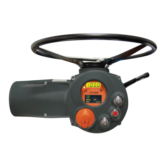
- Page 1 Installation, Operation and Maintenance Manual VCIOM-17023-EN Rev. 7 February 2022 Bettis XTE3000 PROFIBUS DPV1 Module...
- Page 2 Revision Details Installation, Operation and Maintenance Manual February 2022 VCIOM-17023-EN Rev. 7 Revision Details Revision Date Description Prepared Checked Approved February 2022 Migration to new template Revision Details...
-
Page 3: Table Of Contents
Installation, Operation and Maintenance Manual Table of Contents VCIOM-17023-EN Rev. 7 February 2022 Table of Contents Section 1: Introduction Introduction ......................1 Section 2: Operation and Storage Operation and Storage .................... 2 Section 3: Communication Features Communication Features ..................3 Section 4: ICON2000v4_DPV1 Module On Board Indication .................. - Page 4 Table of Contents Installation, Operation and Maintenance Manual February 2022 VCIOM-17023-EN Rev. 7 Section 10: Data Exchange Mode 10.1 Cyclic Communications DPV0 ..............15 10.1.1 Output Data ..................15 10.1.2 Input Data ..................16 10.1.3 Diagnosis Message ................18 10.2 Acyclic Communication DPV1 ..............
-
Page 5: Section 1: Introduction
Installation, Operation and Maintenance Manual Section 1: Introduction VCIOM-17023-EN Rev. 7 February 2022 Section 1: Introduction The ICON2000v4_DPV1 is an electronic module that allows connecting the Bettis electrical actuator XTE3000 to a PROFIBUS DP network. The module has its microprocessor and a program stored internally controls it, it works as a pure bus interface and does not affect the actuator control integrity. -
Page 6: Section 2: Operation And Storage
Section 2: Operation and Storage Installation, Operation and Maintenance Manual February 2022 VCIOM-17023-EN Rev. 7 Section 2: Operation and Storage The module is designed to work and to be stored in the same environment of the actuator. Operation and Storage... -
Page 7: Section 3: Communication Features
Installation, Operation and Maintenance Manual Section 3: Communication Features VCIOM-17023-EN Rev. 7 February 2022 Section 3: Communication Features Communication protocol : PROFIBUS DP according to EN 50170 Network topology : Line (bus) structure. With repeaters tree structures can also be realized Transmission medium : Twisted, screened copper cable according to EN 50170 Data rate... -
Page 8: Section 4: Icon2000V4_Dpv1 Module
Section 4: ICON2000v4_DPV1 Module Installation, Operation and Maintenance Manual February 2022 VCIOM-17023-EN Rev. 7 Section 4: ICON2000v4_DPV1 Module The module consists in a single PCB that is installed inside the actuator housing. It is connected to the XTE3000 base card via strip connector. The internal wiring connects the PROFIBUS data lines to the actuator terminal board. -
Page 9: Section 5: Profibus Dp Description
Installation, Operation and Maintenance Manual Section 5: PROFIBUS DP Description VCIOM-17023-EN Rev. 7 February 2022 Section 5: PROFIBUS DP Description PROFIBUS is a vendor-independent, open field bus standard used in a wide range of application in process automation. Vendor independence and openness are ensured by the international standards EN 50170 and EN 50254. The DP communication profile is designed for data exchange at the field level. The central controllers (as PLC) communicate via serial connection with field devices (as sensors and actuators). Data exchange is mainly cyclic. The central controller (called Master) cyclically reads the input information from the field devices (called Slaves) and cyclically writes the output information to the slaves. -
Page 10: Section 6: Rs485 Transmission Mode
Section 6: RS485 Transmission Mode Installation, Operation and Maintenance Manual February 2022 VCIOM-17023-EN Rev. 7 Section 6: RS485 Transmission Mode The ICON2000v4_DPV1 module uses a half duplex, multidrop, serial communication line RS485. The module communicates with the Masters via its RS485 interface and the transmission media consists in a shielded twisted pair cable. - Page 11 Installation, Operation and Maintenance Manual Section 6: RS485 Transmission Mode VCIOM-17023-EN Rev. 7 February 2022 The ICON2000v4_DPV1 module takes its electrical supply from the actuator power supply module. The RS485 bus transceiver is isolated from the actuator electronics. Also, the voltage supply of the bus termination is isolated.
-
Page 12: Section 7: Slave Redundancy
Section 7: Slave Redundancy Installation, Operation and Maintenance Manual February 2022 VCIOM-17023-EN Rev. 7 Section 7: Slave Redundancy The ICON2000v4_DPV1 is designed to allow the actuator to acts as a redundant slave as described in this section. To achieve the Slave Redundancy, two ICON2000v4_DPV1 modules are mounted in the actuator: in this way the actuator is equipped with a full redundant communication interface as specified by the PROFIBUS Guideline. - Page 13 Installation, Operation and Maintenance Manual Section 7: Slave Redundancy VCIOM-17023-EN Rev. 7 February 2022 Figure 7 Master Master Channel 1 Channel 2 In this layout, the two interfaces may have the same address because the two interfaces are on different channels. A synchronization method must be active between the Master stations to take the information from the Active Slave.
- Page 14 Section 7: Slave Redundancy Installation, Operation and Maintenance Manual February 2022 VCIOM-17023-EN Rev. 7 Figure 9 below shows the wiring necessary in case of redundant slave. The termination must be linked to the data lines only if the actuator is at the beginning or at the end of the bus segment. Figure 9 Terminal ICON2000_DPV1r...
-
Page 15: Section 8: Icon2000V4_Dpv1 Power-Up
Installation, Operation and Maintenance Manual Section 8: ICON2000v4_DPV1 Power-Up VCIOM-17023-EN Rev. 7 February 2022 Section 8: ICON2000v4_DPV1 Power-Up On power-up, the module checks the baud rate and then it waits for the “parameterization” telegram from the Master. The parameterization message contains user information needed for actuator operation and listed in the Section 9: ‘Data exchanged during parameterization‘. -
Page 16: Section 9: Data Exchanged During Parameterization
Section 9: Data Exchanged During Parameterization Installation, Operation and Maintenance Manual February 2022 VCIOM-17023-EN Rev. 7 Section 9: Data Exchanged During Parameterization The following data are sent to the ICON2000v4_DPV1 interface: Table 2. Byte Name Type Range Default Reserved DP V1 1 byte Reserved DP V1 1 byte... - Page 17 Installation, Operation and Maintenance Manual Section 9: Data Exchanged During Parameterization VCIOM-17023-EN Rev. 7 February 2022 Byte 4 Fail-safe action It defines the action of the actuator in case of loss of the bus signal. The action takes place only if the local selector is on REMOTE position and if the bus is operating. When the bus signal restores, the actuator also restores at its normal functioning. —...
- Page 18 Section 9: Data Exchanged During Parameterization Installation, Operation and Maintenance Manual February 2022 VCIOM-17023-EN Rev. 7 Byte 12 Timer Close Direction - Status It enables the Timer function in close direction. — Value 0: Off - disable (default setting) 1: On Byte 13 Timer Close Direction –...
-
Page 19: Cyclic Communications Dpv0
Installation, Operation and Maintenance Manual Section 10: Data Exchange Mode VCIOM-17023-EN Rev. 7 February 2022 Section 10: Data Exchange Mode The following paragraph describes the input and output messages of ICON2000v4_DPV1 interface when working in “data exchange mode” for “cyclic data” and “acyclic data”. In all cases, it is called “input signal” a data flowing from actuator to bus, vice-versa it is called “output signal” a data flowing from bus to slave. -
Page 20: Input Data
Section 10: Data Exchange Mode Installation, Operation and Maintenance Manual February 2022 VCIOM-17023-EN Rev. 7 10.1.2 Input Data BYTE = 0 BYTE = 1 Bit 0 = 1 : Close limit Bit 0 = 1 : Interlock open active Bit 1 = 1 : Open limit Bit 1 = 1 : Interlock close active Bit 2 = 1 : Closing Bit 2 = 1 : Fail-safe action... - Page 21 Installation, Operation and Maintenance Manual Section 10: Data Exchange Mode VCIOM-17023-EN Rev. 7 February 2022 DIN setting Via local operator interface of actuator, the DIN bits can be individually set to 1 if one of the conditions occurs: - open limit - local selected - high-high torque in CL - closed limit...
-
Page 22: Diagnosis Message
Section 10: Data Exchange Mode Installation, Operation and Maintenance Manual February 2022 VCIOM-17023-EN Rev. 7 10.1.3 Diagnosis Message The ICON2000v4_DPV1 interface manages the diagnosis indication coming from the actuator as stated by the PROFIBUS DP V1 standard. When the ICON2000v4_DPV1 interface needs to notify a fault to the master while in data exchange mode, it changes the function code in its response message to “high priority”. - Page 23 Installation, Operation and Maintenance Manual Section 10: Data Exchange Mode VCIOM-17023-EN Rev. 7 February 2022 The diagnose message implemented by ICON2000v4_DPV1 has the following structure: Figure 12 Octet 1 Octet 2 Standard Diagnosis Block Octet 3 Octet 4 6 octets Octet 5 Octet 6 Identifier Related Diagnosis Block...
- Page 24 Section 10: Data Exchange Mode Installation, Operation and Maintenance Manual February 2022 VCIOM-17023-EN Rev. 7 Octet 2 bit0 Diag.Prm_Req (1) = Slave has to be reparameterized Diag.Stat_Diag (1) = During start-up phase, slave not able to provide valid diagnosis data (1) = Fixed at 1 Diag.WD_On (1) = Threshold monitoring activated...
- Page 25 Installation, Operation and Maintenance Manual Section 10: Data Exchange Mode VCIOM-17023-EN Rev. 7 February 2022 10.1.3.2 Identifier Related Diagnosis Block Octet 7 bit0 Header: ICON2000v4_DPV1 report 0x42 Block_Length Number of octets of this block including this header Selection (01) = Identifier Related Diagnostic Octet 8 bit0 Identifier_Diagnosis_Data_Array Identifier_Diagnosis_Entry_1...
- Page 26 Section 10: Data Exchange Mode Installation, Operation and Maintenance Manual February 2022 VCIOM-17023-EN Rev. 7 Octet 13 bit0 Status_Data_ Description: (1) = Motor Thermostat (1) = HI-HI Torque in Opening (1) = HI-HI Torque in Closing (1) = Actuator blocked in Opening (1) = Actuator blocked in Closing (1) = HI-HI Temperature (1) = Position Sensor Failure...
-
Page 27: Acyclic Communication Dpv1
These information can be reached by PROFIBUS class 2 Master with MS2 services. For this purpose and graphical interface, device specific DTM and EDD interface are available for most of host systems. 10.2.1 Nameplate Slot 0, Index 0, length 26 byte: Actuator type Byte Name Range Bettis XTE3000 Bettis XTE3000 0 - 15 Actuator Type 16 byte Biffi F01 2000 Biffi F01 2000 16 - 25... -
Page 28: General Data
Section 10: Data Exchange Mode Installation, Operation and Maintenance Manual February 2022 VCIOM-17023-EN Rev. 7 10.2.2 General Data Slot 1, Index 0, length 4 byte: General data about current working condition Byte Name Description Close limit Open limit Moving Monitor relay Byte 0 Selector in local Selector in remote... - Page 29 Installation, Operation and Maintenance Manual Section 10: Data Exchange Mode VCIOM-17023-EN Rev. 7 February 2022 Slot 2, Index 1, length 22 byte: Recent maintenance information Byte Name Range 0 - 3 Test Date 4 bytes dd-mm-20yy BCD format 4 - 7 Recent log date 4 bytes dd-mm-20yy...
-
Page 30: Alarm And Warning Log
Section 10: Data Exchange Mode Installation, Operation and Maintenance Manual February 2022 VCIOM-17023-EN Rev. 7 Slot 2, Index 4, length 20 byte: Nominal torque and maintenance date Byte Name Range Torque lbf Torque Nm Nominal Torque EU 1 byte Thrust lb Thrust kN 1 - 7 Nominal Torque value... -
Page 31: Maintenance Commands
Installation, Operation and Maintenance Manual Section 10: Data Exchange Mode VCIOM-17023-EN Rev. 7 February 2022 Slot 3, Index 2, length 30 byte: Warning log: the first three records Byte Name Range Warning #1: Code 1 byte 0 - 255 Reserved 1 byte 2 - 5 Warning #1: Date... -
Page 32: Section 11: Data At Local Operator Interface
Section 11: Data at Local Operator Interface Installation, Operation and Maintenance Manual February 2022 VCIOM-17023-EN Rev. 7 Section 11: Data at Local Operator Interface Below are the description of the facilities available by the view and setup menu of XTE3000. 11.1 Bus Control DIN 1 - DIN 6... -
Page 33: Node Report
Installation, Operation and Maintenance Manual Section 11: Data at Local Operator Interface VCIOM-17023-EN Rev. 7 February 2022 Configuration procedure: • Move the local selector to OFF and then press simultaneously OPEN and STOP. Select the language and then enter the password according to the instructions “entering the set-up mode”. -
Page 34: Bus Signal Failure Indication
Section 11: Data at Local Operator Interface Installation, Operation and Maintenance Manual February 2022 VCIOM-17023-EN Rev. 7 STATUS 1 • These informations are from the Active Slave PROFIBUS module. Table 5. Description Reserved DP state 00 = ‘Wait_Prm’ state 01 = ‘Wait_Cfg’ state 10 = ‘DATA_EX’... -
Page 35: Profibus Certificate
Installation, Operation and Maintenance Manual Appendix VCIOM-17023-EN Rev. 7 February 2022 Appendix A: PROFIBUS Certificate Appendix... -
Page 36: Appendix B: Note For Base Card Fw 7.00
Appendix Installation, Operation and Maintenance Manual February 2022 VCIOM-17023-EN Rev. 7 Appendix B: Note for Base Card FW 7.00 This appendix explains the ESD command functionality introduced with base card Firmware version 7.00. The revision of base card can be checked with acyclic data; Nameplate Slot 0, index 0, byte 16 - 25 “SW_VERSION”. - Page 37 Installation, Operation and Maintenance Manual Notes VCIOM-17023-EN Rev. 7 February 2022 This page is intentionally left blank...
- Page 38 P. R. China Székesfehérvár 8000 T +86 22 8212 3300 Hungary The Emerson logo is a trademark and service mark of Emerson Electric Co. T +36 22 53 09 50 Bettis is a mark of one of the Emerson family of companies.