Advertisement
Quick Links
GP 3000
Modification Instructions
Power Panel Modifications
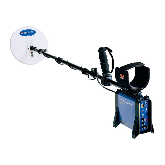
Pictured as you can see is a GP 3000 the mods are the same for all the GP Series. The only
difference will be the position of switches but they will operate the same.
Firstly you will notice the addition of 2 switches, 1 under the on/off and power socket, another is
under the Threshold label. The first switch is labeled Std and Smooth. This switch allows you to
run the detector in a very quiet mode similar to the salt position except the loss of sensitivity is
not as great, it also is similar in function to Enhanced on the GPX4500. There is a slight reduction
of sensitivity and signal response changes slightly. The sensitivity can be overcome by adjusting
the threshold so that the smallest target noise can be heard in conjunction with an audio
enhancer. The suggestion is this switch is used with a mono in ground that is highly mineralized
or salt, turn the threshold down until just audible and adjust the volume up on an enhancer to get
the level back to normal.
IMPORTANT NOTICE: DO NOT SWITCH THE SMOOTH CONTROL SWITCH WITH DETECTOR ON.
TURN OFF DETECTOR BEFORE SWITCHING.
The next switch selects the operating frequency of the detector similar to the 4 position frequency
switch on the SD2000. The switch is position with a left, centre and right direction rather than up
and down. Towards the left (towards the Power socket) is the standard frequency of the detector,
the middle is sensitive for small targets and last switching towards the outside selects the slower
frequency which is for deep larger targets. This will aid in finding those smaller and large targets
that sometimes are just a faint signal.
Advertisement

Related Manuals for Minelab GP 3000


Summary of Contents for Minelab GP 3000
- Page 1 Modification Instructions Power Panel Modifications Pictured as you can see is a GP 3000 the mods are the same for all the GP Series. The only difference will be the position of switches but they will operate the same. Firstly you will notice the addition of 2 switches, 1 under the on/off and power socket, another is under the Threshold label.
- Page 2 Coil Panel Modifications On this panel is 1 additional switch. This switch (Sens 2) gives an additional timing sequence. This gives a large gain in sensitivity and depth when activated and the detector soil switch in the sensitive position. Up on this switch will be the active or on position. Tests performed in this position and with sensitive selected have shown a very large increase in target response and depth on small and large targets.