
Related Manuals for Baxi HP40-XX-MB


Summary of Contents for Baxi HP40-XX-MB
- Page 1 Installer operation manual - Wired controller Heat Pump air/water "inverter" Baxi HP40-XX-MB Mono 2 AWHP 4-16MR...
- Page 2 • This manual gives detailed description of the precautions that should be brought to your attention during operation. • In order to ensure correct service of the wired controller, please read this manual carefully before using the unit. • For convenience of future reference, keep this manual after reading it. CONTENTS 1 GENERAL SAFETY PRECAUTIONS •...
-
Page 3: General Safety Precautions
1 GENERAL SAFETY PRECAUTIONS 1.1 About the documentation • The precautions described in this document cover very important topics, follow them carefully. • All activities described in the installation manual must be performed by an authorized installer. 1.1.1 Meaning of warnings and symbols DANGER Indicates a situation that results in death or serious injury. -
Page 4: For The User
1.2 For the user • If you are not sure how to operate the unit, contact your installer. • The appliance is not intended for use by persons, including children, with reduced physical, sensory or mental capabilities, or lack of experience and knowledge, unless they have been given supervision or instruction concerning use of the appliance by a person responsible for their safety. -
Page 5: Glance Of The User Interface
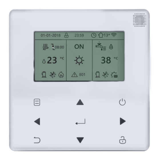
2 A GLANCE OF THE USER INTERFACE 2.1 The appearance of the wired controller Enter the menu structure from the home page Turn on or off the space operation mode or DHW mode turn on or off the function in Navigate the the menu structure cursor on the... -
Page 6: Status Icons
2.2 Status icons Lock icon Weekly schedule icon At the next scheduled action, the Timer icon desired temp. will decrease. Outdoor ambient temp. the desired temp. will not change. WLAN icon the desired temp. will decrease. the desired temp. Domestic hot water will increase. - Page 7 3 USING HOME PAGES 3.1 About home pages You can use the home pages to read out and change settings that are meant for daily usage. What you can see and do on the home pages is described where applicable. Depending on the system layout, the following home pages may be possible: •...
- Page 8 home page3 : If the DHW MODE is set NON , and if ‘’WATER FLOW TEMP.’’ is set YES, ‘’ROOM TEMP.’’ is set YES,There will be a main page and an additional one. The system functions include floor heating and space cooling for fan coil, home page 3 will appear: MAIN PAGE...
-
Page 9: About The Menu Structure
home page4 : If the DHW MODE is set YES. There will be a main page and an additional one. The system functions include floor heating, space cooling for fan coil and domestic hot water, home page 4 will appear: MAIN PAGE ADDITIONAL... -
Page 10: Basic Usage
5 BASIC USAGE 5.1 Screen Unlock If the icon is on the screen, the controller is locked. The following page is displayed: Press any key, the icon will flash. Long press the key. The icon will disappear, the interface can be controlled. -
Page 11: Turning On/Off Controls
The interface will be locked if there is no handing for a long time(about 120 seconds) If the interface is unlocked, long press , the interface will be locked. Long press Long press 5.2 Turning ON/OFF controls • Use the interface to turn on or off the unit for space heating or cooling. The ON/OFF of the unit can be controlled by the interface if the ROOM THERMOSTAT is NON. - Page 12 1 ) When the cursor is on the temperature of space operation mode side (In- cluding heat mode , cool mode and auto mode ), press key to turn on/off space heating or cooling. If the DHW TYPE is set NON,the following pages will display: If the TEMP.
- Page 13 Use the room thermostat to turn on or off the unit for space heating or cooling. ① The room thermostat is set to YES(see ‘’ROOM THERMOSTAT SETTING’’ on «Installation, User and Service Manual») the unit is turned on or off by the room thermostat, press on the interface, the following page will display: Turning on or off cooling/ heating...
- Page 14 Use the interface to turn on or off the unit for DHW.Press ‘’ ► ’’、 ‘’▼’’on home page,the black cursor will appear: 2)When the cursor is on DHW operation mode. Press key to turn on/off the DHW mode. If the space operation is ON,the following pages will display: If the space operation mode is OFF,the following pages will display:...
-
Page 15: Adjusting The Temperature
5.3 Adjusting the temperature Press ‘’ ◄ ‘’、 ‘’▲’’ on home page, the black cursor will appear: • If the cursor is on the temperature, use the ‘’◄’’、 ‘’ ► ’’ to select and use ‘’▼’’、 ‘’▲’’ to adjust the temperature. -
Page 16: Adjusting Space Operation Mode
5.4 Adjusting space operation mode • Adjusting space operation mode by interface. Go to ‘’MENU’’ > ‘’SPACE OPERATION MODE’’ . Press , the following page will appear: OPERATION MODE Operation mode setting: HEAT COOL AUTO CONFIRM... - Page 17 • There are three modes to be selected including HEAT, COOL and AUTO mode. Use the ‘’ ◄ ’’, ‘’ ► ’’ to scroll, press to select. Even if you don’t press button and exit the page by pressing button, the mode would still effective if the cursor have be moved to the operation mode.
-
Page 18: Safety Precaution
• Adjust space operation mode by the room thermostat, see ‘’ROOM THERMOSTAT’’ on «Installation, User and Service Manual». Go to MENU>OPERATION MODE, if you press any key to select or adjust, the following page will appear: Cool/heat mode is controlled by the room thermostat. - Page 19 WARNING Please entrust the distributor or professionals to install the unit. Installation by other persons may lead to imperfect installation, electric shock or fire. Strictly follow this manual. Improper installation may lead to electric shock or fire. Reinstallation must be performed by professionals. improper installation may lead to electric shock or fire.
-
Page 20: Preparation Before Installation
6.2 Other Precautions 6.2.1. Installation location Do not install the unit in a place with much oil, steam, sulfide gas. Otherwise, the product may deform and fail. Install in the room where the user spends most of their time, in a draught-free environment. - Page 21 3) The shielded cable must be connected stable to the ground, or transmission may fail. 4) Do not attempt to extend the shielded cable by cutting, if it is necessary, use Terminal Connection Block to connect. 5) After finishing connection, do not use Megger to have the insulation check for the signal wire.
-
Page 22: Back Cover Installation
Input Voltage(A/B) 13.5VAC Wiring size 0.75mm The rotating coded switch S3(0-F) on the main control board of hydraulic module is used for set the modbus address. By default the units have this coded switch positioned=0, but this corresponds to the modbus address 16 , while the others positions corresponds the number, e.g. - Page 23 Screw hole installed on the three M4X20 Screw hole installed on 86 Electrician box, use two M4X25 Back cover Signal switching wires 1 ) Use straight head screwdriver to insert in the buckling position in the bottom of wired controller, and spin the screwdriver to take down the back cover. (Pay attention to spinning direction, otherwise this will damage the back cover!) 2) Use three M4X20 screws to directly install the back cover on the wall.
- Page 24 Left down side wire outlet Cutting place of left down side wire outlet Wall hole and wiring hole Wiring Diameter: Φ8--Φ10 60mm hole Putty Putty Putty Trap Trap Trap Avoid the water entering into the wired remote controller, use trap and putty to seal the connectors of wires during wiring installation.
-
Page 25: Front Cover Installation
6.4 Front cover installation After adjusting the front cover and then buckle the front cover; avoid clamping the communication switching wire during installation. Sensor can not be affected with damp. Install correctly the back cover and firmly buckle the front cover and back cover, otherwise will make the front cover drop off. -
Page 26: Modbus Mapping Table
7 MODBUS MAPPING TABLE 7.1 Modbus Port Communication Specification Port: RS-485; the wired controller XYE is the communication port for connecting with the hydraulic module. H1 and H2 are the Modbus communication ports. Communication address: It is consistent with the DIP switch address of the hydraulic module. - Page 27 1 (PLC:40002) Setting the mode 1: Auto; 2: Cool; 3: Heat; Others: Invalid 2 (PLC:40003) Setting water temperature T1s Water temperature T1s is corresponding to the floor heating. 3 (PLC:40004) Setting air temperature Ts The room temperature range is between 17°C and 30°C, and is valid when there is Ta.
- Page 28 112 (PLC:40113) Refrigerant liquid side temperature in °C 113 (PLC:40114) Refrigerant gas side temperature in °C 114 (PLC:40115) Room temperature, in °C 115 (PLC:40116) Water tank temperature 116 (PLC:40117) Pressure 1 Outdoor unit high pressure value, in kPA 117 (PLC:40118) Pressure 2 Outdoor unit low pressure value, in kPA 118 (PLC:40119)
-
Page 29: Parameter Setting
132 (PLC:40133) Unit target frequency 133 (PLC:40134) Dc bus current In A (PLC:40135) Dc bus voltage The actual value/10, in V 135 (PLC:40136) TF module temperature Feedback on outdoor unit,in °C Hydraulic module curve T1S The corresponding calculated value of zone 1 136 (PLC:40137) calculated value 1 Hydraulic module curve... - Page 30 211 (PLC:40212) Parameter setting 2 BIT15 Reserved BIT14 Reserved BIT13 Reserved BIT12 Reserved BIT11 Reserved BIT10 Reserved BIT9 Reserved BIT8 Define the port, 0=remote ON/OFF; 1=DHW heater BIT7 Smart grid, 0=NON; 1=YES BIT6: Enable or disable the Tw2, 0=NON ; 1=YES BIT5: Setting the high/low temperature of cooling mode T1S BIT4:...
- Page 31 T4_AHS_on Ambient temperature for enabling the external heater AHS, range: -15~10°C, setting interval: -5°C 237 (PLC: 40238) dT1_AHS_on Temperature return difference for enabling the external heater AHS, 238 (PLC: 40239) range: 2~10°C; default setting: 5°C t_AHS_delay Delay time for enabling the external heater AHS, range: 5~120 min; 240 (PLC: 40241) default setting: 30 min t_DHWHP_max...
- Page 32 The type of power input limitation, 0=NON, 1~8=type 1~8, default:0 269 (PLC: 40270) HB:t_T4_FRESH_C range:0.5~6 hour, setting interval:0.5 hour, 270 (P LC: 40271 ) sending value=actural value*2 LB:t_T4_FRESH_H range:0.5~6 hour, setting interval:0.5 hour, sending value=actural value*2 T_PUMPI_DELAY range:2~20 hour, setting interval:0.5 hour, 271 (PLC: 40272) sending value=actural value*2: EMISSION TYPE...
- Page 33 Error Value Content code Pressure sensor fault Outlet water for zone 2 temp. sensor(Tw2) fault Outlet water temp. sensor(Tw_out) fault 3 times PP protection and Tw_out<7℃ Communication fault between hydraulic module parallel Communication error between main board and thermostat transfer board Inverter module board EE PROM fault H6 display 10 times in 2 hours Low pressure protection (Pe<0.6) occurred 3 times in 1 hour...
- Page 36 For Ireland For United Kingdom www.baxi.co.uk www.baxipottertonmyson.ie 0344 871 1545 00353 (0)1 4590870 Baxi, Brooks House Baxi Potterton Myson Unit F 5&6, Calmount Park, Calmount Road, Coventry Road, Warwick, CV34 4LL. Ballymount , Dublin 12, Ireland. 7799027-001-03 7799027 - v03 - 08022022...