Table of Contents
Advertisement
Available languages
Available languages
Quick Links
Advertisement
Chapters
Table of Contents

Related Manuals for Baxi RILANCIO+


Summary of Contents for Baxi RILANCIO+
- Page 1 RILANCIO+ SISTEMA PER LA GESTIONE DI UN IMPIANTO A ZONE AD INCASSO Istruzioni di installazione MANAGEMENT SYSTEM FOR A BUILT-IN ZONE SYSTEM Installation instructions SYSTÈME POUR LA GESTION D'UNE INSTALLATION À ZONES À ENCASTRER Instructions d'installation...
-
Page 2: Table Of Contents
Gentile Cliente, la nostra Azienda ritiene che il Suo nuovo prodotto soddisferà tutte le Sue esigenze. L’acquisto di un nostro prodotto garantisce quanto Lei si aspetta: un buon funzionamento ed un uso semplice e razionale. Quello che Le chiediamo è di non mettere da parte queste istruzioni senza averle prima lette: esse contengono informazioni utili per una corretta ed efficiente gestione della Suo prodotto. -
Page 3: Descrizione Simboli
DESCRIZIONE SIMBOLI AVVERTENZA Rischio di danno o di malfunzionamento dell'apparecchio. Prestare particolare attenzione alle avvertenze di pericolo che riguardano possibili danni alle persone. PERICOLO ALTA TENSIONE Parti elettriche in tensione, pericolo di shock elettrico. INFORMAZIONI IMPORTANTI Informazioni da leggere con particolare attenzione perchè utili al corretto funzionamento della caldaia. DIVIETO GENERICO Vietato effettuare/utilizzare quanto specificato a fianco del simbolo. -
Page 4: Installazione
2. INSTALLAZIONE L'apparecchio va installato all'interno della cassa/dima fornita a parte. Assicurarsi che il modello della cassa dima/dima sia corretto. 2.1 INSTALLAZIONE CASSA DIMA La cassa/dima deve essere inserita nel muro in una nicchia ricavata a tale scopo e bloccata con le apposite zanche laterali. Assicurarsi che l’installazione permetta una agevole manutenzione. -
Page 5: Collegamento Elettrico
4. COLLEGAMENTO ELETTRICO L’apparechio deve essere collegato elettricamente ad una rete d’alimentazione 230V~ monofase con terra mediante il cavo a tre fili in dotazione. L’allacciamento deve essere effettuato tramite un interruttore bipolare (lo stesso che alimenta la caldaia), con apertura dei contatti di almeno 3 mm. In caso di sostituzione del cavo d’alimentazione, deve essere utilizzato un cavo armonizzato “HAR H05 VV-F”... -
Page 6: Regolazione Delle Pompe Automodulanti
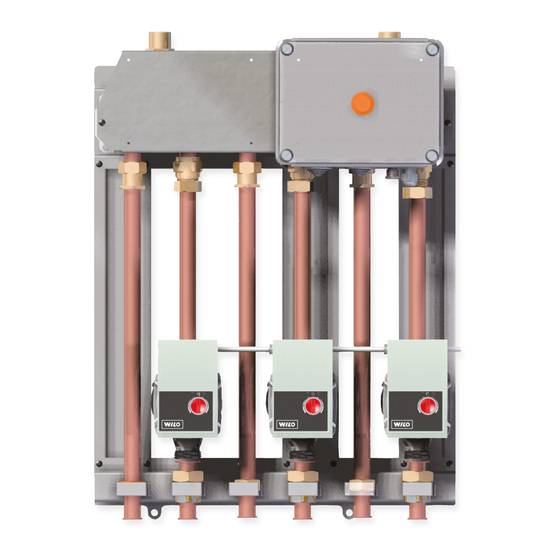
5. REGOLAZIONE DELLE POMPE AUTOMODULANTI Le pompe automodulanti sono dotate di una manopola con la quale è possibile attivare e disattivare tutte le funzioni e di un indicatore a LED posizionato intorno alla manopola stessa. Nella tabella che segue è riportata la diagnostica ed il significato della segnalazione luminosa del LED. - Page 7 7222564.01 (3-09/15)
- Page 8 Dear Customer, Our company is confident our new product will meet all your requirements. Buying one of our products guarantees all your expectations: good performance combined with simple and rational use. Please do not put this booklet away without reading it first: it contains useful information for the correct and efficient use of your product.
-
Page 9: Description Of Symbols
DESCRIPTION OF SYMBOLS WARNING Risk of damage to or malfunction of the appliance. Pay special attention to the warnings concerning danger to people. DANGER - HIGH VOLTAGE Live components - electrocution hazard. IMPORTANT INFORMATION Information to read with particular care as it is useful for the correct operation of the boiler. GENERIC PROHIBITION It is forbidden to do/use the things indicated alongside the symbol. -
Page 10: Installation
2. INSTALLATION The appliance must be installed inside the template box, supplied separately. Ensure that the model of the template box is correct. 2.1 INSTALLING THE TEMPLATE BOX The template box must be fitted into the wall in a niche created for the purpose and blocked with special rag bolts at the sides. Make sure the installation allows easy access for maintenance. -
Page 11: Electrical Connection
4. ELECTRICAL CONNECTION The appliance must be electrically connected to a 230V~ single-phase power mains with earth by means of the three-core cable provided. Use a two-pole switch (the same one powering the boiler) with a contact gap of at least 3 mm. When replacing the power supply cable, fit a harmonised “HAR H05 VV-F”... -
Page 12: Adjusting The Self-Modulating Pumps
5. ADJUSTING THE SELF-MODULATING PUMPS The self-modulating pumps have a knob for enabling and disabling all the functions, and a LED indicator around the same knob. The diagnostics and meaning of the light signals of the LED are indicated in the table below. ZONE PUMPS Turn the knob to (DP-v) and the pump regulates the speed by adjusting the DP according to the pressure loss of the system. - Page 13 7222564.01 (3-09/15)
- Page 14 Cher Client, notre Maison ose espérer que votre nouvel appareil saura répondre à toutes vos exigences. L'achat de l'un de nos produits vous apportera ce que vous recherchez : un fonctionnement irréprochable et une utilisation simple et rationnelle. Nous vous demandons de lire cette notice d'utilisation avant d’utiliser votre chaudière car elles fournissent des informations utiles pour une gestion correcte et efficace de votre produit.
-
Page 15: Description Symboles
DESCRIPTION SYMBOLES AVERTISSEMENT Risque d'endommagement ou anomalie de fonctionnement de l'appareil. Faire très attention aux avertissements qui concernent des risques dommages aux personnes. DANGER HAUTE TENSION Pièces électriques sous tension, risque de choc électrique. INFORMATIONS IMPORTANTES Informations à lire très attentivement car elles sont utiles pour le fonctionnement correct de la chaudière. INTERDICTION GÉNÉRALE Il est interdit d'effectuer/utiliser ce qui est indiqué... -
Page 16: Installation
2. INSTALLATION L'appareil doit être installé à l'intérieur du boîtier/gabarit fourni séparément. S'assurer que le modèle du boîtier/gabarit soit correct. 2.1 INSTALLATION BOÎTIER/GABARIT Le boîtier/gabarit doit être installé dans le mur, dans un encastrement spécialement réalisé à cette fin, et bloqué à l'aide des agrafes latérales. -
Page 17: Branchement Électrique
4. BRANCHEMENT ÉLECTRIQUE L'appareil doit être branché électriquement à un réseau d'alimentation 230 Vca monophasé muni de terre en se servant du cordon à trois fils fourni. Le branchement doit être effectué au moyen d'un interrupteur bipolaire (le même que celui qui alimente la chaudière) ayant une distance d'ouverture des contacts d'au moins 3 mm. -
Page 18: Réglage Des Pompes Auto-Modulantes
5. RÉGLAGE DES POMPES AUTO-MODULANTES Les pompes auto-modulantes sont dotées d'un bouton avec lequel il est possible d'activer et désactiver toutes les fonctions et d'un indicateur à LED positionné autour du bouton. Le tableau qui suit indique le diagnostic et la signification des signalisations lumineuses du LED. - Page 19 7222564.01 (3-09/15)
- Page 20 CG_2640 7222564.01 (3-09/15)
- Page 21 7222564.01 (3-09/15)
- Page 22 CG_2613 7222564.01 (3-09/15)
- Page 23 7222564.01 (3-09/15)
- Page 24 Q [l/h] Q [l/h] 7222564.01 (3-09/15)
- Page 25 Q [l/h] Q [l/h] 7222564.01 (3-09/15)
- Page 26 Q [l/h] Q [l/h] 7222564.01 (3-09/15)
- Page 27 7222564.01 (3-09/15)
- Page 28 7222564.01 (3-09/15)