Toshiba Satellite A100 User Manual
Toshiba satellite a100/ satellite pro a100 portable personal computer user's manual
Hide thumbs
Also See for Satellite A100:
- Maintenance manual (293 pages) ,
- User manual (171 pages) ,
- Manual (52 pages)
Table of Contents

Related Manuals for Toshiba Satellite A100


Summary of Contents for Toshiba Satellite A100
- Page 1 TOSHIBA Satellite A100/ Satellite Pro A100 Portable Personal Computer User’s Manual...
- Page 2 This manual has been validated and reviewed for accuracy. The instructions and descriptions it contains are accurate for the TOSHIBA Satellite A100/Satellite Pro A100 Portable Personal Computer at the time of this manual’s production. However, succeeding computers and manuals are subject to change without notice.
-
Page 3: Safety Instructions
TruSurround XT, WOW HD, Circle Surround Xtract, TruBass, SRS 3D , Defini- tion and FOCUS technologies are incorporated under license from SRS Labs, Inc. InterVideo and WinDVD are registered trademarks of the InterVideo Inc. WinDVD Creator is trademarks of the InterVideo Inc. Other trademarks and registered trademarks not listed above may be used in this manual. -
Page 4: Fcc Information
When setting up the computer for work, place it on a level surface. FCC information Product Name:Satellite A100/ Satellite Pro A100 Model number:PSAA0/ PSAA1 FCC notice “Declaration of Conformity Informa- tion”... -
Page 5: Fcc Conditions
Connect the equipment into an outlet on a circuit different from that to which the receiver is connected. Consult the dealer or an experienced radio/TV technician for help. WARNING: Only peripherals complying with the FCC class B limits may be attached to this equipment. Operation with non-compliant peripherals or peripherals not recommended by TOSHIBA is likely to result in inter- ference to radio and TV reception. - Page 6 BSMI Notice (Taiwan Only) TOSHIBA declares, that the product: Satellite A100/Satellite Pro A100 con- forms to the following Standards: Supplementary Information: This product is carrying the CE-Mark in accordance with the related European Directives. Responsible for CE-Marking is TOSHIBA Europe, Hammfelddamm 8, 41460 Neuss, Germany.
- Page 7 This Class B digital apparatus meets all requirements of the Canadian Interfer- ence-Causng Equipment Regulations. Cet appareil numérique de la class B respecte toutes les exgences du Règlement sur le matériel brouileur du Canada. Modem warning notice Conformity Statement The equipment has been approved to [Commission Decision “CTR21”] for pan- European single terminal connection to the Public Switched Telephone Network (PSTN).
-
Page 8: Region Selection
Japan regulations Region selection If you are using the computer in Japan, technical regulations described in the Telecommunications Business Law require that you select the Japan region mode. It is illegal to use the modem in Japan with any other selection. Redial Up to two redial attempts can be made. -
Page 9: Telephone Company Procedures
If you have any questions about your telephone line, such as how many pieces of equipment you can connect to it, the telephone company will provide this infor- mation upon request. Telephone company procedures The goal of the telephone company is to provide you with the best service it can. In order to do this, it may occasionally be necessary for them to make changes in their equipment, operations, or procedures. - Page 10 Instructions for IC CS-03 certified equipment The Industry Canada label identifies certified equipment. This certification means that the equipment meets certain telecommunications network protec- tive, operational and safety requirements as prescribed in the appropriate Terminal Equipment Technical Requirements document(s). The Department does not guarantee the equipment will operate to the user’s satisfaction.
- Page 11 Notes for Users in Australia and New Zealand Modem warning notice for Australia Modems connected to the Australian telecoms network must have a valid Austel permit. This modem has been designed to specifically configure to ensure com- pliance with Austel standards when the country/region selection is set to Austra- lia.
- Page 12 Some parameters required for compliance with Telecom’s PTC Specifica- tions are dependent on the equipment (PC) associated with this modem. The associated equipment shall be set to operate within the following limits for compliance with Telecom Specifications: (a) There shall be no more than 10 call attempts to the same number within any 30 minute period for any single manual call initiation, and (b) The equipment shall go on-hook for a period of not less than 30 seconds between the end of one attempt and the beginning of the next.
-
Page 13: General Conditions
The transmit level from this device is set at a fixed level and because of this there may be circumstances where the performance is less than optimal. Before reporting such occurrences as faults, please check the line with a standard Telepermitted telephone, and only report a fault if the phone perfor- mance is impaired. -
Page 14: Important Notice
This symbol may not stick depending on the country and region where you purchased. Optical disk drive standards TOSHIBA Satellite A100/Satellite Pro A100 computer is shipped with one of the following drives preinstalled: DVD-ROM, CD-RW/DVD-ROM, or DVD Super Multi (+-R Double Layer) drive. - Page 15 ment, transmission and disposition may be subject to claims for damages and penalties. Avoid using a telephone (other than a cordless type) during an electrical storm. There may be a remote risk of electric shock from lightning. Do not use the telephone to report a gas leak in the vicinity of the leak. Use only the power cord indicated in this manual.
- Page 16 CD-RW/DVD-ROM drive safety instructions CAUTIONS: 1. The drive employs a laser system. To ensure proper use of this product, please read this instruction manual carefully and retain for future reference. Should the unit ever require maintenance, contact an authorized service location. 2.
- Page 17 Toshiba Samsung TS-L462C Location of the required label HLDS GCC-4244A Location of the required label PRODUCT IS CERTIFIED BY THE MANUFACTURER TO COMPLY WITH DHHS RULES 21 CFR SUBCHAPTER J APPLICABLE AT THE DATE OF MANUFACTURE. MANUFACTURED: TOSHIBA SAMSUNG STORAGE TECHNOLOGY CORPORATION 580, HORIKAWA-CHO, SAIWAI-KU, KAWASAKI-SHI, KANAGAWA, 212-...
- Page 18 DVD Super Multi (+-R Double Layer) drive safety instructions CAUTIONS: 1. The drive employs a laser system. To ensure proper use of this product, please read this instruction manual carefully and retain for future reference. Should the unit ever require maintenance, contact an authorized service location.
- Page 19 TEAC DV-W28EB Location of the required label HDLS GMA-4082N Location of the required label CERTIFICATION TISH PRODUCT COMPLIES WITH DHHS RULES 21 CFR CHAPTER 1, SUBCHAPTER J APPLICABLE DATE OF MANUFAC- TURE MANUFACTURED: TEAC CORPORATION 3-7-3 NAKA-CHO, MUSASHINO-SHI, TOKYO, JAPAN COMPLIES WITHFDA RADIATION PERFORMANCE STANDARDS, 21 CFR SUBCHAPTER J.
- Page 20 Pioneer DVR-K16 Location of the required label NEC ND-7550N Location of the required label COMPLIES WITHFDA RADIATION PERFORMANCE STANDARDS, 21 CFR SUBCHAPTER J. MANUFACTURED: Manufactured by PIONEER CORPORATION 4-1. Meguro 1-chome, Meguro-ku TOKYO 153-8654, JAPAN COMPLIES WITHFDA RADIATION PERFORMANCE STANDARDS, 21 CFR SUBCHAPTER J.
- Page 21 CAUTION: This appliance contains a laser system and is classified as a “CLASS 1 LASER PRODUCT.” To use this model properly, read the instruction manual carefully and keep this manual for your future reference. In case of any trouble with this model, please contact your nearest “AUTHORIZED service station.”...
- Page 22 OBS! Apparaten innehåller laserkomponent som avger laserstråining överstigande gränsen för laserklass 1. VAROITUS. Suojakoteloa si saa avata. Laite sisältää laserdiodin, joka lähetää näkymätöntä silmilie vaarallista lasersäteilyä. CAUTION: USE OF CONTROLS OR ADJUST- MENTS OR PERFORMANCE OF PROCE- DURES OTHER THAN THOSE SPECIFIED IN THE OWNER’S MANUAL MAY RESULT IN HAZARDOUS RADIATION EXPOSURE.
-
Page 23: Table Of Contents
Table of Contents Preface Manual contents... xxvii Conventions ... xxviii Abbreviations ... xxviii Icons ... xxviii Keys... xxviii Key operation... xxix Display ... xxix Messages ... xxix General Precautions PC card overheating ... xxxi Mobile phone ... xxxi Chapter 1 Introduction Equipment checklist ... - Page 24 AV Buttons... 2-9 System indicators ... 2-10 USB diskette drive ... 2-12 Optical Media drive ... 2-13 Region codes for DVD drives and media... 2-13 Writable discs ... 2-13 CD-RW/DVD-ROM drive ... 2-14 DVD Super Multi (+-R Double Layer) drive... 2-14 AC adaptor...
- Page 25 Connecting 3 1/2" diskette drive ... 4-3 Disconnecting 3 1/2" diskette drive... 4-4 Using optical media drives ... 4-4 Loading discs... 4-5 Removing discs ... 4-7 AV Button function (Provided with some models)... 4-9 Express Media Player ... 4-9 Writing CDs on CD-RW/DVD-ROM drive ... 4-10 Important message (CD-RW/DVD-ROM drive) ...
- Page 26 LAN... 4-28 Connecting LAN cable ... 4-28 Disconnecting LAN cable... 4-29 Cleaning the computer ... 4-30 Moving the computer... 4-30 Heat dispersal ... 4-31 Chapter 5 The Keyboard Typewriter keys ... 5-1 F1 ... F12 function keys ... 5-2 Soft keys: Fn key combinations ... 5-2 Emulating keys on enhanced keyboard...
- Page 27 Maximizing battery operating time ... 6-11 Retaining data with power off ... 6-12 Extending battery life ... 6-12 Replacing the battery pack ... 6-13 Removing the battery pack ... 6-13 Installing the battery pack ... 6-15 Starting the computer by password... 6-15 Power-up modes...
- Page 28 Additional AC adaptor ... 8-11 USB FDD Kit ... 8-11 External monitor ... 8-11 Television ... 8-13 i.LINK (IEEE1394) ... 8-13 Precautions... 8-14 Connecting... 8-14 Disconnecting ... 8-15 Security lock... 8-15 Chapter 9 Troubleshooting Problem solving process ... 9-1 Preliminary checklist ... 9-1 Analyzing the problem ...
- Page 29 Standby/Hibernation ... 9-20 LAN... 9-21 Wireless LAN ... 9-21 i.LINK (IEEE1394) ... 9-21 TOSHIBA support ... 9-22 Before you call ... 9-22 Appendix Appendix A Specifications... A-1 Appendix B Display Controller and Modes ... B-1 Appendix C AT Commands... C-1 Appendix D S-registers ...
-
Page 31: Manual Contents
A100 computer. This powerful, lightweight notebook computer is designed to provide years of reliable, high-performance computing. This manual tells how to set up and begin using your Satellite A100/ Satellite Pro A100 computer. It also provides detailed information on configuring your com- puter, basic operations and care, using optional devices and troubleshooting. -
Page 32: Conventions
User’s Manual Chapter 6, Power and Power-Up resources and battery save modes. Chapter 7, HW Setup and Passwords, explains how to configure the computer using the HW Setup program. It also tells how to set a password. Chapter 8, Optional Devices, describes the optional hardware available. -
Page 33: Key Operation
Key operation Some operations require you to simultaneously use two or more keys. We iden- tify such operations by the key top symbols separated by a plus sign (+). For example, Ctrl + C means you must hold down Ctrl and at the same time press C. If three keys are used, hold down the first two and at the same time press the third. - Page 34 User’s Manual xxxiv...
-
Page 35: General Precautions
General Precautions TOSHIBA computers are designed to optimize safety, minimize strain and with- stand the rigors of portability. However, certain precautions should be observed to further reduce the risk of personal injury, damage to the computer or impared performance. Be certain to read the general precautions below and to note the cautions included in the text of the manual. -
Page 36: Pc Card Overheating
User’s Manual PC card overheating Some PC cards can become hot with prolonged use. Overheating of a PC card can result in errors or instability in the PC card operation. Also be careful when you remove a PC card that has been used for a long time. Mobile phone Use of mobile phones can interfere with the audio system. -
Page 37: Copy Protection
Non-applicable Icons Certain notebook chassis are designed to accommodate all possible config- urations for an entire product series. Your selected model may not have all the features and specifications corresponding to all of the icons or switches shown on the notebook chassis, unless you have selected all those features. Wireless LAN/Atheros For 802.11a, b and g The transmission speed over the wireless LAN and the distance over which... -
Page 38: Lcd Brightness And Eye Strain
User’s Manual SRS audio enhancements are available in the Microsoft Windows operation system only. Images All images are simulated for purposes of illustration. Express Media Player The Express Media Player is not a Windows based application. Battery life will be less than when using similar applications in the Windows Operating System. LCD Brightness and Eye Strain Your LCD display has a brightness approaching that of a TV device. -
Page 39: Chapter 1 Introduction
Carefully unpack your computer. Save the box and packing materials for future use. Hardware Check to make sure you have all the following items: Satellite A100/Satellite Pro A100 Portable Personal Computer Universal AC adaptor and power cord USB diskette drive (Provided with some models) Modular cable (Provided with some models) -
Page 40: Software
• TOSHIBA Zooming Utility • TOSHIBA Controls • TOSHIBA Virtual Sound Documentation: • Satellite A100/Satellite Pro A100 Resorce Guide • Microsoft Windows XP manual package • Instruction Manual for Safety & Comfort • End User License Agreement Product Recovery Media... -
Page 41: Features
Features The computer uses TOSHIBA’s advanced Large Scale Integration (LSI), Com- ple-mentary Metal-Oxide Semiconductor (CMOS) technology extensively to provide compact size, minimum weight, low power usage, and high reliability. This computer incorporates the following features and benefits: Processor Built-in The computer is equipped with a Dothan processor, on- die 32KB instruction L1 cache and 2MB L2 cache memory. -
Page 42: Memory
User’s Manual Memory Slots PC4200 256 MB or 512 MB or 1024 MB memory mod- ules can be installed in the two memory slots for a max- imum of 2048 MB system memory. Level 2 cache A 1 MB (Intel ®... - Page 43 DVD Super Multi Some models are equipped with a full-size DVD Super (+-R Double Layer) Multi (+- R Double Layer) drive module that lets you drive record data to rewritable CD/DVDs as well as run either 12 cm (4.72") or 8 cm (3.15") CD/DVDs without using an adaptor.
- Page 44 User’s Manual Display The computer’s LCD panel supports high-resolution video graphics. The screen can be set at a wide range of viewing angles for maximum comfort and readability. Built-in Thin-film transistor color LCD is available in three sizes: • 15.4" WXGA, 1280 horizontal x 800 vertical pixels •...
- Page 45 External monitor 15-pin, analog VGA port supports VESA DDC2B com- patible functions. Universal Serial Bus Four Universal Serial Bus (USB) enables chain connec- (USB2.0) tion of a number of USB-equipped devices to one port on your computer. i.LINK™ This port enables high-speed data transfer directly from (IEEE 1394) external devices such as digital video camera.
- Page 46 User’s Manual Communications Modem An internal modem provides capability for data and fax communication. It supports V.90 (V.92). Refer to V.90 section in Appendix E. The speed of date transfer and fax depends on analog telephone line conditions. It has a modem jack for connecting to a telephone line.
- Page 47 • Wired Equivalent Privacy (WEP) data encryption, based on 152 bit encryption algorithm (Atheros mod- ule type). • Wired Equivalent Privacy (WEP) data encryption, based on 128 bit encryption algorithm(Intel module type). • Advanced Encryption Standard (AES) data encryp- tion, based on 256 bit encryption algorithm (Atheros module type).
-
Page 48: Special Features
User’s Manual Special features The following features are either unique to TOSHIBA computers or are advanced features, which make the computer more convenient to use. Hot keys Key combinations let you quickly modify the system configuration directly from the keyboard without run- ning a system configuration program. - Page 49 Panel power on/off This feature turns power to the computer off when the display panel is closed and turns it back on when the panel is opened. You can specify the setting in the When I close the lid item of the Setup Action tab in TOSHIBA Power Saver.
-
Page 50: Utilities
User’s Manual Utilities This section describes preinstalled utilities and tells how to start them. For details on operations, refer to each utility’s online manual, help files or readme.txt files. TOSHIBA Assist TOSHIBA Assist is a graphical user interface that pro- vides easy access to help and services. -
Page 51: Options
TOSHIBA Config- ConfigFree is a suite of utilities to allow easy control of Free communication device and network connections. Con- figFree also allows you to find communication prob- lems and create profiles for easy switching between location and communication networks. You can boot ConfigFree from the menu bar as follows. - Page 52 User’s Manual Battery pack An additional battery pack 4 cells Type (TBD), 6 cells Type (TBD), 8 cells Type (TBD) can be purchased from your TOSHIBA dealer. The battery pack is identical to the one that came with your computer. Use it as a spare or replacement.
-
Page 53: Chapter 2 The Grand Tour
The Grand Tour This chapter identifies the various components of your computer. Become famil- iar with each component before you operate the computer. Front with the display closed Figure 2-1 shows the computer’s front with its display panel in the closed posi- tion. - Page 54 User’s Manual Multiple Digital Slide the cover toward the medium to access the Multi- Media Card Slot ple Digital Media Card Slot of your computer. This slot lets you easily transfer data from devices, such as digital camera and PDA, that use flash memory (SD/MS/MS Pro/MMC/xD memory cards).
-
Page 55: Left Side
Left side Figure 2-2 shows the computer’s left side. AN VENT XTERNAL MONITOR PORT Figure 2-2 The left side of the computer External monitor This 15-pin port lets you connect an external monitor. port Fan vent Provides air flow for the fan. CAUTION: Be careful not to block the fan vent. -
Page 56: Right Side
User’s Manual PC Card Slot The PC card slot can accommodate one 5 mm PC card (Type II). The slot supports 16-bit PC card and 32-bit CardBus PC card. CAUTION: Keep foreign objects out of the PC card slot. A pin or similar object can damage the computer’s circuitry Express Card The computer provides Express Card slot on its left... -
Page 57: Back Side
Wirless commu- Slide this switch toward the right of the computer to turn nication switch on Wireless communication. Slide it toward the left of the computer to turn off the functions. (Provided with some models) Security lock slot A security cable attaches to this slot. The optional secu- rity cable anchors your computer to a desk or other large object to deter theft. - Page 58 User’s Manual LAN jack This jack lets you connect to a LAN. The adaptor has built-in support for Ethernet LAN (10 megabits per sec- ond, 10BASE-T), Fast Ethernet LAN (100 megabits per second, 100BASE-Tx). The LAN has two indicators. See Chapter 4, DC IN 19V The AC adaptor connects to this socket.
-
Page 59: Underside
Underside Figure 2-5 shows the underside of the computer. Make sure the display is closed before turning over your computer. ATTERY ATTERY PACK EMORY MODULE COVER Figure 2-5 The underside of the computer Battery pack The battery pack powers the computer when the AC adaptor is not connected. -
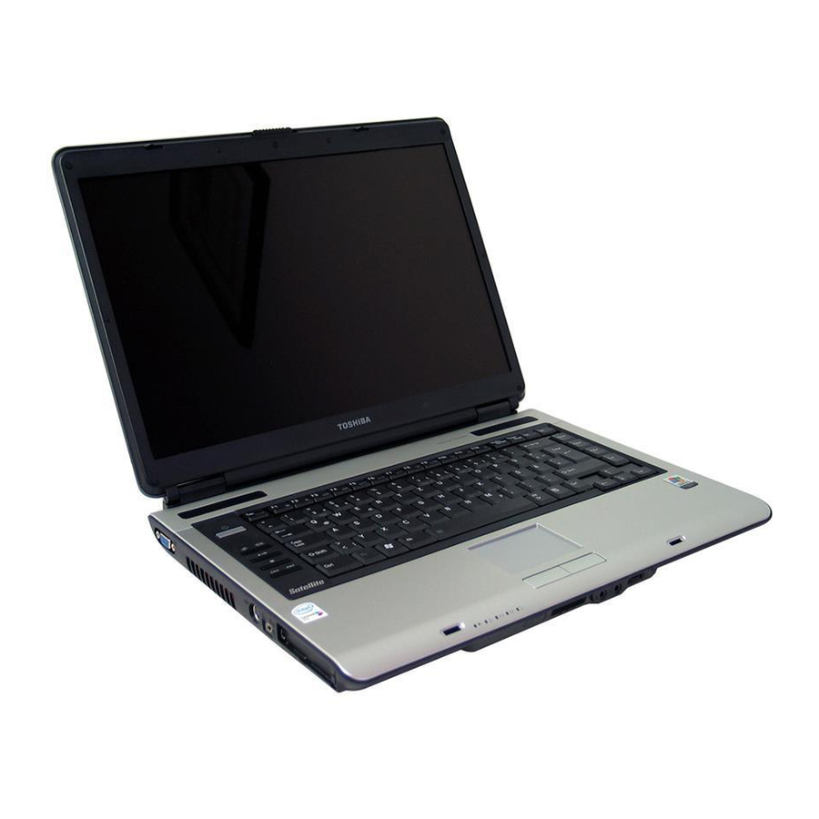
Page 60: Front With The Display Open
User’s Manual Front with the display open Figure 2-6 shows the front of the computer with the display open. To open the display, slide the display latch on the front of the computer and lift the display up. Position the display at a comfortable viewing angle. ISPLAY SCREEN ISPLAY INGE... -
Page 61: Av Buttons
Touch Pad Moves the pointer and selects or activates items on the screen. Can be set to perform other mouse functions, such as scrolling, selecting, and double-clicking. Touch Pad Function like the left and right buttons on an external Control Buttons mouse. -
Page 62: System Indicators
User’s Manual System indicators Figure 2-7 shows the system indicators, which light when various computer operations are in progress. DC IN Figure 2-7 Systems indicators Power source/system indicators DC IN The DC IN indicator glows blue when DC power is sup- plied from the AC power adaptor. -
Page 63: Keyboard Indicator
The figures below show the positions of the keypad overlay indicators and the CapsLock indicator. When the F10 key indicator glows the keypad overlay lets you control the cursor. When the F11 key indicator glows the keypad overlay lets you enter numbers. UMERIC MODE RROW MODE Figure 2-8 Keypad overlay indicators... -
Page 64: Usb Diskette Drive
User’s Manual USB diskette drive A 3 1/2" diskette drive accommodates 1.44-megabyte or 720-kilobyte diskettes. It connects to the USB port. NDICATOR ISKETTE SLOT JECT BUTTON Figure 2-10 USB diskette drive Disk-In-Use This indicator lights when the diskette is being Indicator accessed. -
Page 65: Optical Media Drive
Optical Media drive CD-RW/DVD-ROM drive, DVD-ROM drive, DVD Super Multi (+-R Double Layer) drive. An ATAPI interface controller is used for CD/DVD-ROM opera- tion. When the computer is accessing a CD/DVD, an indicator on the drive glows. Region codes for DVD drives and media CD-RW/DVD-ROM, DVD Super Multi (+-R Double Layer) drive and media are manufactured according to the specifications of six marketing regions. -
Page 66: Cd-Rw/Dvd-Rom Drive
User’s Manual DVDs DVD-R, DVD+R and DVD+R DL discs can be written only once. The recorded data cannot be erased or changed. DVD-RW, DVD+RW and DVD-RAM discs can be recorded more than once. Formats The drives support the following formats: •... - Page 67 DVD-RW write 6 speed (maximum) DVD+R write 8 speed (maximum) DVD+RW write 8 speed (maximum) DVD+R DL write 4 speed (maximum) DVD-R DL write 4 speed (maximum) DVD-RAM write 5 speed (maximum) CD-R write 24 speed (maximum) CD-RW write 16 speed (maximum, ultra-speed media) Optical Media drive 2-15...
-
Page 68: Ac Adaptor
User’s Manual AC adaptor The AC adaptor converts AC power to DC power and reduces the voltage sup- plied to the computer. It can automatically adjust to any voltage from 100 to 240 volts and to a frequency of either 50 or 60 hertz, enabling you to use the com- puter in almost any region. -
Page 69: Chapter 3 Getting Started
Getting Started This chapter provides basic information to get you started using your computer. It covers the following topics: Setting up your work space — for your health and safety NOTE: Be sure also to read Instruction Manual for Safety & Com- fort. -
Page 70: Setting Up Your Work Space
User’s Manual Setting up your work space Establishing a comfortable work site is important for you and your computer. A poor work environment or stressful work habits can result in discomfort or seri- ous injury from repetitive strain to your hands, wrists or other joints. Proper ambient conditions should also be maintained for the computer’s operation. -
Page 71: Seating And Posture
Set the computer on a flat surface at a comfortable height and distance. The display should be no higher than eye level to avoid eye strain. Place the computer so that it is directly in front of you when you work and make sure you have adequate space to easily operate other devices. -
Page 72: Lighting
User’s Manual Lighting Proper lighting can improve legibility of the display and reduce eye strain. Position the computer so that sunlight or bright indoor lighting does not reflect off the screen. Use tinted windows, shades or other screen to elimi- nate sun glare. -
Page 73: Connecting The Ac Adaptor
Connecting the AC adaptor Attach the AC adaptor when you need to charge the battery or you want to oper- ate from AC power. It is also the fastest way to get started, because the battery pack will need to be charged before you can operate from battery power. The AC adaptor can be connected to any power source supplying from 100 to 240 volts and 50 or 60 hertz. -
Page 74: Opening The Display
User’s Manual 3. Plug the power cord into a live wall outlet. The Battery and DC IN indicator on the front of the computer should glow. Opening the display The display panel can be rotated in a wide range of angles for optimal viewing. 1. -
Page 75: Starting Up For The First Time
OWER UTTON Figure 3-5 Turning on the power Starting up for the first time When you first turn on the power, the computer’s initial screen is the Microsoft ® Windows XP Startup Screen Logo. Follow the on-screen directions. Turning off the power The power can be turned off in one of the following modes: Shut down (Boot), Hibernation or Standby mode. -
Page 76: Hibernation Mode
User’s Manual ® 3. If you are using Windows From the Turn off computer menu select Turn off. 4. Turn off the power to any peripheral devices. CAUTION: Do not turn the computer or devices back on immedi- ately. Wait a moment to let all capacitors fully discharge. Hibernation mode The hibernation feature saves the contents of memory to the hard disk when the computer is turned off. -
Page 77: Starting Hibernation
Starting Hibernation To enter Hibernation mode, follow the steps below. Windows XP 1. Click Start. 2. Select Turn Off Computer. 3. Open the Turn Off Computer dialog box. 4. Select Hibernate. Automatic Hibernation The computer will enter Hibernate mode automatically when you press the power button or close the lid. - Page 78 User’s Manual CAUTIONS: 1. Before entering Standby mode, be sure to save your data. 2. Do not install or remove a memory module while the com- puter is in standby mode. The computer or the module could be damaged. 3. Do not remove the battery pack while the computer is in standby mode (unless the computer is connected to an AC power source).
-
Page 79: Restarting The Computer
When you turn the power back on, you can continue where you left when you shut down the computer. NOTES: 1. When the computer is shut down in standby mode, the power indicator glows amber. 2. If you are operating the computer on battery power, you can lengthen the operating time by shutting down in hibernation mode. -
Page 80: Using The Express Media Player Software Backup Cd
User’s Manual not removed the partition, your operating system, files and saved documents will remain on your computer. NOTE: The following procedure is for systems that have the Recov- ery Disc Creator icon on the desktop. If the Express Media Player Software is not provided on a separate software back-up CD, or is not included on your computer's recovery media, Toshiba rec- ommends that you create a backup copy of the software and store it in a conve- nient location. -
Page 81: Restoring The Preinstalled Software From The Product Recovery Media
Restoring the preinstalled software from the Product Recovery Recover to the initial state Update Express Media Player functions (if you have a newer version of the SW) Delete Express Media Player Cancel Restoring the preinstalled software from the Product Recovery Media If preinstalled files are damaged, use the Product Recovery Media to restore them. - Page 82 User’s Manual 3-14...
-
Page 83: Chapter 4 Operating Basics
Operating Basics This chapter gives information on basic operations including using the Touch Pad, USB diskette drive, optical media drives, the microphone, the internal modem, wireless communication and LAN. It also provides tips on caring for your computer, diskettes and CD/DVDs. Using the Touch Pad/Lux Pad To use the Touch Pad, simply touch and move your finger tip across it in the direction you want the on-screen pointer to go. - Page 84 User’s Manual Lux Pad Button Function ONFIG AUNCHING Figure 4-2 Functionality of each button on Lux Pad Mail Start your mail box for you to receive and send mails. ConfigFree ConfigFree is a suite of utilities to allow easy con- trol of communication devices and network connec- tions.
-
Page 85: Using The Usb Diskette Drive
Using the USB diskette drive A 3 1/2" diskette drive connects to the computer’s USB port. It accommodates 1.44-megabyte or 720-kilobyte diskettes. Refer to Chapter 2, The Grand Tour, for more information. Connecting 3 1/2" diskette drive To connect the drive, plug the diskette drive connector into a USB port. Refer to Figure 4-1. -
Page 86: Disconnecting 3 1/2" Diskette Drive
User’s Manual Disconnecting 3 1/2" diskette drive When you have finished using the diskette drive, follow the procedures below to disconnect it: 1. Wait for the indicator light to go out to make sure all diskette activity has stopped. CAUTION: If you disconnect the diskette drive or turn off the power while the computer is accessing the drive you may lose data or dam- age the diskette or the drive. -
Page 87: Loading Discs
Loading discs To load CD/DVDs, follow the steps below and refer to figures 4-4 to 4-8. 1. a. When the power is on, press the DVD-ROM eject button to open the drawer slightly. Figure 4-4 Pressing the DVD-ROM eject button b. - Page 88 User’s Manual 2. Grasp the drawer gently and pull until it is fully opened. Figure 4-6 Pulling the drawer open 3. Lay the CD/DVD, label side up, in the drawer. Figure 4-7 Inserting a CD/DVD Note: When the drawer is fully opened, the edge of the computer will extend slightly over the CD/DVD tray.
-
Page 89: Removing Discs
2. Do not keep foreign matter from entering the drive. Check the back edge of the tray to make sure it carries no debris before closing the drive. 4. Press gently at the center of the CD/DVD until you feel it click into place. The CD/DVD should lie below the top of the spindle, flush with the spindle base. - Page 90 User’s Manual CAUTIONS: 1. When the drawer pops open slightly, wait a moment to make sure the CD/DVD has stopped spinning before pull- ing the drawer fully open. 2. Turn off the power before you use the eject hole. If the CD/DVD is spinning when you open the drawer, the CD/ DVD could fly off the spindle and cause injury.
-
Page 91: Av Button Function (Provided With Some Models)
AV Button function (Provided with some models) This section describes a button function. Figure 4-10 AV Button Windows mode Icon AV Button (WinDVD5) CD/DVD Detect and activate media Play/Pause Play/Pause Stop Stop Previous Previous chapter Next Next chapter *Windows Media Player 10 Express Media Player Express Media Player is a quick play feature that enables users to perform DVD and CD playback without using Windows. -
Page 92: Writing Cds On Cd-Rw/Dvd-Rom Drive
User’s Manual 2. Depending the video being played, noise may be present. 3. When WinDVD uses pre-installation. 4. External display output (DVI/S-Video out) is not supposed to support. Writing CDs on CD-RW/DVD-ROM drive You can use the CD-RW/DVD-ROM drive to write data to either CD-R or CD- RW discs. -
Page 93: When Writing Or Rewriting
Writing CDs on CD-RW/DVD-ROM drive TOSHIBA has confirmed the operation of CD-R and CD-RW media of the man- ufacturers above. Operation of other media cannot be guaranteed. CD-RW can generally be rewritten about 1,000 times. However, the actual number of rewrites is affected by the quality of the media and the way it is used. -
Page 94: Disclaimer (Cd-Rw/Dvd-Rom Drive)
User’s Manual Set the computer on a level surface and avoid places subject to vibration such as airplanes, trains, or cars. Do not use an unstable surface such as a stand. Keep mobile phones and other wireless communication devices away from the computer. -
Page 95: Before Writing Or Rewriting
Writing CD/DVDs on DVD Super Multi (+-R Double Layer) drive If you fail to do so, the DVD Super Multi (+-R Double Layer) drive may not function properly, and you may fail to write or rewrite, lose data or incur other damage. - Page 96 User’s Manual Note: This drive cannot use discs that allow writing of 8 speeds or more (DVD-R, DVD+R, DVD+RW), 6 speeds or more (DVD-RW). If the disc is poor in quality, dirty or damaged, writing or rewriting errors may occur. Be careful to check the disc for dirt or damage before you use it. The actual number of rewrites to CD-RW, DVD-RW, DVD+RW or DVD- RAM is affected by the quality of the disc and the way it is used.
-
Page 97: When Writing Or Rewriting
Writing CD/DVDs on DVD Super Multi (+-R Double Layer) drive Operate the computer in the full-power mode. Do not use power-saving fea- tures. Format 4 is not supported. Do not write while virus check software is running. Wait for it to finish, and then disable virus detection programs including any software that checks files automatically in the background. -
Page 98: Disclaimer (Dvd Super Multi (+-R Double Layer) Drive)
User’s Manual Keep mobile phones and other wireless communication devices away from the computer. Always copy data from the HDD to the DVD-RAM. Do not use cut-and- paste. The original data will be lost if there is a write error. Disclaimer (DVD Super Multi (+-R Double Layer) drive) TOSHIBA does not bear responsibility for the following:... -
Page 99: Data Verification
Writing CD/DVDs on DVD Super Multi (+-R Double Layer) drive RecordNow! cannot record in packet format. You might not be able to use the “Exact Copy” function of RecordNow! to back up a DVD-R/-R DL/-RW or DVD+R/+R DL/+RW disc that was made with other software on a different DVD-R/-R DL/-RW or DVD+R/+RW recorder. -
Page 100: Dla For Toshiba
User’s Manual 3. Mark the Verify data written to the disc after burning check box in the Data Options. 4. Click the OK button. DLA for TOSHIBA Note the following limitations when you use DLA: This software supports only rewritable discs (DVD+RW/+R DL, DVD-RW/ -R DL, and CD-RW). -
Page 101: How To Learn More About Intervideo Windvd Creator
Writing CD/DVDs on DVD Super Multi (+-R Double Layer) drive 4. Click the Advanced tab in the System Properties window. 5. Click the Settings icon in the “Performance” section. 6. Click the Advanced tab in the Performance Options window. 7. Click the Change icon in the “virtual memory” section. 8. - Page 102 User’s Manual Operate the computer at Full Power. Do not use power-saving features. While you are editing DVD, you can display previews. However, if another application is running, the preview might not display properly. WinDVD Creator cannot show video on the external monitor when in simultaneous mode.
-
Page 103: Media Care
A maximum of about 2 hours of video data can be written in DVD Video format to DVD-R/+R/-RW/+RW disc. WinDVD Creator cannot export to DVD-Audio, VideoCD, miniDVD for- mat. WinDVD Creator can write DVD-RAM/+RW in VR format, but the disc may only play on your computer. -
Page 104: Diskettes
User’s Manual 3. Do not write on, apply a sticker to, or otherwise mark the surface of the CD/ DVD that contains data. 4. Hold the CD/DVD by its outside edge or the edge on the center hole. Fin- gerprints on the surface can prevent the drive from properly reading data. 5. -
Page 105: Modem
input is output to the speaker (throughput) and the speaker volume is too loud or too close to the microphone. You can control throughput by adjusting the volume of your speaker or through the Mute function in the Master Volume panel. Refer to your Windows documentation for details on using the Master Volume panel. -
Page 106: Properties Menu
User’s Manual 3. Click the icon with the primary mouse button to display a list of regions that the modem supports. A sub menu for telephony location information will also be displayed. A check will appear next to the currently selected region and telephony location. -
Page 107: Modem Selection
A warning dialog box is displayed if current settings for region code and telephony location are incorrect. Modem Selection If the computer cannot recognize the internal modem, a dialog box is displayed. Select the COM port for your modem to use. Dialing Properties Select this item to display the dialing properties. -
Page 108: Wireless Communications
User’s Manual Disconnecting To disconnect the internal modem cable, follow the steps below. 1. Pinch the lever on the connector in the telephone jack and pull out the con- nector. 2. Disconnect the cable from the computer in the same manner. Wireless communications The computer’s wireless communication function supports both Wireless LAN and Bluetooth devices. -
Page 109: Bluetooth Wireless Technology
Be sure to enable WEP (encryption) function. Otherwise your computer will allow the illegal access by outsider through wireless LAN to cause illegal instruction, eavesdropping, and loss or destruction of stored data. TOSHIBA strongly recommends the customer to enable the WEP function. TOSHIBA is not liable for the eavesdropping of data due to the use of Wire- less LAN and the damage thereof. -
Page 110: Wireless Communication Indicator
User’s Manual Wireless communication Indicator The wireless communication indicator indicates the status of the wireless com- munication functions. Indicator status Indication Indicator off Wireless communication switch is set to off. Automatic power down because of overheating. Power malfunction Indicator glows Wireless communication switch is on. -
Page 111: Disconnecting Lan Cable
If you are using Ethernet LAN (10 megabits per second, 10BASE-T), connect with a category 3 cable, CAT3, or higher. To connect the LAN cable, follow the steps below. 1. Turn off the power to the computer and to all external devices connected to the computer. -
Page 112: Cleaning The Computer
User’s Manual Cleaning the computer To help ensure long, trouble-free operation, keep the computer free of dust and use care with liquids around the computer. Be careful not to spill liquids into the computer. If the computer does get wet, turn the power off immediately and let the computer dry completely before you turn it on again. -
Page 113: Heat Dispersal
Heat dispersal To protect from overheating, the CPU has an internal temperature sensor. If the computer’s internal temperature rises to a certain level, the cooling fan is turned on or the processing speed is lowered. You can select whether to control the CPU temperature by turning on the fan first, then if necessary, lowering the CPU speed. - Page 114 User’s Manual 4-32...
-
Page 115: Chapter 5 The Keyboard
The Keyboard The computer’s keyboard layouts are compatible with a 101/102-key enhanced keyboard. By pressing some keys in combination, all the 101/102-key keyboard functions can be executed on the computer. The number of keys on your keyboard depends on which country/region’s key- board layout your computer is configured with. -
Page 116: F1 ... F12 Function Keys
User’s Manual F1 ... F12 function keys The function keys, not to be confused with Fn, are the 12 keys at the top of your keyboard. These keys are dark gray, but function differently from the other dark gray keys. F1 through F12 are called function keys because they execute programmed functions when pressed. -
Page 117: Hot Keys
Soft keys: Fn key combinations tion in this chapter for more information on how to operate these keys. The power on default for both settings is off. Press Fn + F12 (ScrLock) to lock the cursor on a specific line. The power on default is off. - Page 118 User’s Manual Instant security: Press Fn + F1 to lock the keyboard and blank the screen to prevent others from accessing your data. To restore the screen and original set- tings, press any key. When a dialog box appears, enter the screensaver password and click OK.
- Page 119 Display selection: Press Fn + F5 to change the active display device. When you press these hot keys a dialog box appears. Only selectable devices will be displayed. Hold down Fn and press F5 again to change the device. When you release Fn and F5, the selected device will change.
- Page 120 User’s Manual Touch Pad: Pressing Fn + F9 in a windows environment enables or disables the Touch Pad function. When you press these hot keys, the current setting will change and be displayed as an icon. Display resolution selection: Press Fn + space keys to change the display resolution.
-
Page 121: Fn Sticky Key
Windows special keys Fn Sticky key You can use the Toshiba Accessibility Utility to make the Fn key sticky, that is, you can press it once, release it, and they press an “F number” key. To start the Toshiba Accessibity Utility, click start, point to All Programs, point to TOSHIBA, point to Utilities and click Accessibility. -
Page 122: Arrow Mode
User’s Manual Arrow mode To turn on the Arrow mode, press Fn + F10. The Arrow mode indicator lights. Now try cursor and page control using the keys shown in figure 5-1. Press Fn + F10 again to turn off the overlay. Numeric mode To turn on the Numeric mode, press Fn + F11. -
Page 123: Temporarily Using Overlay (Overlay Off)
Temporarily using overlay (overlay off) While using the normal keyboard, you can temporarily use the keypad overlay without turning it on: 1. Press and hold down Fn. 2. Check the keyboard indicators. Pressing Fn turns on the most recently used overlay. - Page 124 User’s Manual 5-10...
-
Page 125: Chapter 6 Power And Power-Up Modes
Chapter 6 Power and Power-Up Modes The computer’s power resources include the AC adaptor and internal batteries. This chapter gives details on making the most effective use of these resources including charging and changing batteries, tips for saving battery power, and power up modes. - Page 126 User’s Manual Table 1: Power conditions Power on Battery fully • Operates adaptor charged • No charge connected • LED: Battery Blue Battery • Operates partially • Charge charged or • LED: Battery Amber no charge No battery • Operates installed •...
-
Page 127: Power Indicators
Power indicators The Battery, DC IN and Power indicators on the system indicator panel alert you to the computer’s operating capability and battery charge status. Battery indicator Check the Battery indicator to determine the status of the battery. The following indicator lights indicate the battery status: Flashing amber The battery charge is low. -
Page 128: Power Indicator
User’s Manual Power indicator Check the Power indicator to determine the power status. Blue Indicates power is being supplied to the computer and the computer is turned on. Blinking amber Indicates the power was turned off while the computer was in Supsend mode. No light Under any other conditions, the indicator does not light. -
Page 129: Real Time Clock Battery
To ensure that the battery pack maintains its maximum capacity, operate the computer on battery power at least once a month until the battery pack is fully discharged. Refer to Extending battery life computer is continuously operated on AC power, more than a month, the battery may fail to retain a charge. - Page 130 User’s Manual Caution: Indicates a potentially hazardous situation, Which if not avoided, may result in moderate or minor injury or property damage. Note: Provides important information. Danger 1. Never try to dispose of the battery pack by burning or expose it to a heating device such as a microwave oven.
- Page 131 Warning 1. Never allow caustic electrolyte fluid leaked from a battery pack to contact your eyes, skin or clothing. If caustic electrolyte fluid should contact your eyes, immediately wash your eyes with large amounts of running water and seek medical attention, to help prevent eye damage. It electrolyte fluid should contact your skin immediately wash it under running water to pre- vent rash.
-
Page 132: Charging The Batteries
User’s Manual 6. Be sure to monitor the remaining battery power. If the battery pack and real time clock battery discharge completely. Standby and Suspend will not function and data in memory will be lose. Also, the computer might register an incorrect time and date. -
Page 133: Battery Charging Notice
Procedures To recharge a battery pack while it is installed in the computer, connect the AC adaptor to the DC IN socket and plug the other end into a working outlet. The Battery indicator glows amber when the battery is being charged. CAUTION: Use only the computer connected to an AC power source or the optional TOSHIBA Battery charger to charge the bat- tery pack. -
Page 134: Monitoring Battery Capacity
User’s Manual The battery has not been used for a long time. The battery has completely discharged and been left in the computer for a long time. A cool battery is installed in a warm computer. In such case, follow the steps below. 1. -
Page 135: Maximizing Battery Operating Time
Maximizing battery operating time A battery’s usefulness depends on how long it can supply power on a single charge. How long the charge lasts in a battery depends on: How you configure the computer (for example, whether you enable battery- power saving options). -
Page 136: Retaining Data With Power Off
User’s Manual Retaining data with power off When you turn off your computer with fully charged batteries, the batteries retain data for the following approximate time periods: Battery pack (4 cell) Battery pack (6 cell) Battery pack (8 cell) RTC battery Extending battery life To maximize the life of your battery pack: At least once a month, disconnect the computer from a power source and... -
Page 137: Replacing The Battery Pack
If you are not going to use the computer for more than eight hours, discon- nect the AC adaptor. Store spare battery packs in a cool dry place out of direct sunlight. Replacing the battery pack When the battery pack reaches the end of its operating life you will need to install a new one. - Page 138 User’s Manual Figure 6-1 Slide the locking latch to the unlocked position 6. Slide the battery release latch to free the battery pack for removal, then lift up the battery pack. ATTERY ELEASE ATCH Figure 6-2 Removing the battery pack 7.
-
Page 139: Installing The Battery Pack
Installing the battery pack To install a battery pack, follow the steps below. CAUTION: The battery pack is a lithium ion battery, which can explode if not properly replaced, used, handled or disposed of. Dis- pose of the battery as required by local ordinances or regulations. Use only batteries recommended by TOSHIBA as replacements. -
Page 140: Power-Up Modes
User’s Manual CAUTION: If you enter the password incorrectly three times in a row, the computer shuts off. In this case, you must turn the computer back on to retry password entry. Power-up modes The computer has the following power-up modes: Boot: Computer shuts down without saving data. -
Page 141: Chapter 7 Hw Setup And Passwords
HW Setup and Passwords This chapter explains how to use TOSHIBA HW Setup program to configure your computer and how to set passwords. HW Setup TOSHIBA HW Setup lets you configure settings for pointing devices, display, CPU, boot priority, keyboard, USB, LAN, general, password, and device config. Note: If the supervisor password is set, access to the TOSHIBA HW Setup program can be prevented when the user password is used to log on to the computer. -
Page 142: Hw Setup Window
User’s Manual HW Setup window The HW Setup window contains the following tabs: Pointing Devices, Display, CPU, Boot Priority, Keyboard, USB, LAN, General, Password, and Device Con- fig. There are also three buttons: OK, Cancel and Apply. Accepts your changes and closes the HW Setup win- dow. - Page 143 2. Enter a password of up to 10 characters. The character string you enter is displayed as a string of asterisks. For example, if you enter a password con- sisting of four characters, the display is shown as: Enter Password: **** Note: If you click the OK button before entering the password, Not registered will appear on the display.
- Page 144 User’s Manual You will not be able to access the password option in the HW Setup. In this case you must turn the power off and back on to retry the procedure. 4. Follow the same procedures described in the earlier section, How to set the password, to set a new user password.
-
Page 145: Boot Priority
Boot Priority Boot Priority Options This option sets the priority for booting the computer. Select from the following settings: FDD -> HDD -> CD-ROM -> LAN HDD -> FDD -> CD-ROM -> LAN FDD -> CD-ROM -> LAN -> HDD HDD ->... - Page 146 User’s Manual To change the boot drive, follow the steps below. 1. Hold down F12 and boot the computer. 2. Use the up/down cursor keys to select boot device you want and press Enter. NOTES: 1. If a supervisor password is set, the menu above does not appear when you use the user password to start the computer.
- Page 147 Built-in LAN Enables built-in LAN functions. (Default) Enabled Disables built-in LAN functions. Disabled HW Setup...
- Page 148 User’s Manual...
-
Page 149: Chapter 8 Optional Devices
Optional Devices Optional devices can expand the computer’s capabilities and its versatility. The following optional devices are available from your TOSHIBA dealer: Cards/memory PC cards SD, MS (MS Pro), MMC, xD memory cards Memory expansion Express cards Power devices Additional battery pack (4 cell, 6 cell and 8 cell) Additional AC adaptor Peripheral devices USB FDD Kit... -
Page 150: Pc Cards
User’s Manual PC cards The computer is equipped with a PC card expansion slot that can accommodate one 5 mm Type II card. Any PC card that meets industry standards (manufac- tured by TOSHIBA or other vendor) can be installed. The slots support 16-bit PC cards, including PC card 16’s multifunction card and CardBus PC cards. -
Page 151: Removing A Pc Card
Removing a PC card To remove the PC card, follow the steps below. ® 1. In Windows XP, open the Safely Remove Hardware icon on the sys- tem tray and disable the PC card. 2. Press the eject button of the PC card you want to remove to extend the but- ton. -
Page 152: Express Card
User’s Manual Express Card Installing an Express Card The Express Card slot is located on the left side of the computer. You can install one Express Card in the slot. Windows’ hot-install feature lets you install Express Card while the computer’s power is on. -
Page 153: Removing An Express Card
Removing an Express Card To remove the Express Card, follow the steps below. ® 1. In Windows XP, open the Safely Remove Hardware icon on the sys- tem tray and disable the Express Card. 2. Press the Express Card slightly to make it stretch out. 3. -
Page 154: Multiple Digital Media Card Slot (Supported With Some Models)
User’s Manual Multiple Digital Media Card Slot ported with some models) The computer is equipped with a Multiple Digital Media Card Slot that can accom- modate Secure Digital (SD)/Memory Stick (MS)/Memory Stick Pro (MS Pro)/ Multi Media Card (MMC)/xD memory cards. These memory cards let you easily transfer data from devices, such as digital cameras and Personal Digital Assistants, that use SD/MS/MS Pro/MMC/xD memory cards. -
Page 155: Removing A Sd/Ms/Ms Pro/Mmc/Xd Card
Multiple Digital Media Card Slot (Supported with some models) 1. Memory Stick Duo/Memory Stick Pro Duo/Mini SD card is not supported. 2. Two kinds of cards will not work at the same time. Please insert only one card when using Multiple Digital Media Card Slot. -
Page 156: Memory Expansion
User’s Manual Memory expansion You can install additional memory in the computer’s memory module to increase the amount of RAM. CAUTION: Only memory modules with the following parts numbers can be installed: 256MB: PA3389U-1M25 512MB: PA3412U-1M51 1GB: PA3411U-1M1G Installing memory module To install a memory module, make sure the computer is in boot mode then: 1. - Page 157 Figure 8-7 Removing the cover 6. Insert the memory module into the connector on the computer. Press the module carefully and firmly to ensure a solid connection. 7. Push the module down so that it lies flat and is secured by two latches. CAUTION: Do not touch the connectors on the memory module or on the computer.
-
Page 158: Removing Memory Module
User’s Manual Removing memory module To remove the memory module, make sure the computer is in boot mode then: 1. Turn the computer off and remove all cables connected to the computer. CAUTIONS: 1. If you use the computer for a long time, the memory mod- ules will become hot. -
Page 159: Additional Battery Pack (4 Cell, 6 Cell And 8 Cell )
Additional battery pack (4 Cell, 6 Cell and 8 Cell ) Additional battery pack (4 Cell, 6 Cell and 8 Cell ) You can increase the portability of the computer with additional battery packs (4 Cell: PA3451U-1BAS/PA3451U-1BRS, 6 Cell: PA3465U-1BAS/PA3465U- 1BRS, 8 Cell: PA3457U-1BAS/PA3457U-1BRS). - Page 160 User’s Manual You can use the HW Setup to select between Auto-Selected and Simultaneous displays. Refer to Chapter 7, HW Setup and If you have selected Simultaneous under the Display options of the HW Setup, both the external monitor and the internal LCD will be active when you turn on the computer.
-
Page 161: Television
Television A television can be connected to the video out port on the computer. To connect a television, follow the steps below. 1. Turn the computer off. 2. Use a video cable (not supplied) to connect the television to the video out port. -
Page 162: Precautions
User’s Manual Precautions 1. Make a back-up of your data before transferring it to the computer. There is a possibility that the original data will be damaged. There is a particular risk that some frames will be deleted in the case of digital video transfer. TOSHIBA assumes no liability for such loss of data. -
Page 163: Disconnecting
f. When multiple IEEE1394 devices are connected to a PC, the devices may not correctly be identified. This problem may occur when Win- ® dows XP is restarted while the devices are connected or when the power to the IEEE1394 devices is turned on before the PC is turned on. If it occurs, disconnect the IEEE1394 cables and then reconnect them. - Page 164 User’s Manual 8-16...
-
Page 165: Chapter 9 Troubleshooting
Troubleshooting TOSHIBA designed the computer for durability. However, should problems occur, following the procedures in this chapter can help to determine the cause. All readers should become familiar with this chapter. Knowing what might go wrong can help prevent problems from occurring. Problem solving process Resolving problems will be much easier if you observe the following guidelines: Stop immediately when you recognize a problem exists. -
Page 166: Analyzing The Problem
User’s Manual Check that your diskette is correctly inserted and that the diskette’s write protect tab is correctly set. Make notes of your observations and keep them in a permanent error log. This will help you describe your problems to your dealer. If a problem recurs, the log will help you identify the problem faster. -
Page 167: Hardware And System Checklist
Hardware and system checklist This section discusses problems caused by your computer’s hardware or attached peripherals. Basic problems may occur in the following areas: System start-up Self test Power Password Keyboard LCD panel Hard disk drive DVD-ROM drive CD-RW/DVD-ROM drive DVD +-R/+-RW drive DVD Super Multi drive Diskette drive... -
Page 168: Self Test
User’s Manual Self test When the computer starts up, the self-test will be run automatically, and the fol- lowing will be displayed: In Touch with Tomorrow TOSHIBA This message remains on the screen for a few seconds. If the self test is successful, the computer tries to load the operating system. Depending on how the Boot Priority is set in the Hardware Setup, the computer tries to load first from drive A then from drive C, or first from drive C then from drive A. -
Page 169: Overheating Power Down
Overheating power down If the computer’s internal temperature becomes too high, the computer will auto- matically shut down. AC power If you have trouble turning on the computer with the AC adaptor connected, check the DC IN indicator. Refer to Chapter 6, more information. - Page 170 User’s Manual Problem Procedure Battery doesn’t If the battery is completely discharged, it will not charge when the AC begin charging immediately. Wait a few minutes. adaptor is attached (Battery indicator If the battery still does not charge, make sure does not glow the outlet is supplying power.
-
Page 171: Password
Password Problem Procedure Cannot enter pass- Refer to the word Setup and Keyboard Keyboard problems can be caused by your setup configuration. For more informa- tion refer to Chapter 5, The Keyboard Problem Procedure Some letter keys pro- Check that the numeric keypad overlay is not duce numbers selected. -
Page 172: Hard Disk Drive
User’s Manual Problem Procedure Problems above Refer to your software’s documentation to deter- remain unresolved or mine if the software is causing the difficulty. other problems occur Contact your dealer if the problems continue. Hard disk drive Problem Procedure Computer does not Check if a diskette is in the diskette drive or a boot from hard disk CD-ROM is in the optical media drive. -
Page 173: Cd-Rw/Dvd-Rom Drive
CD-RW/DVD-ROM drive For more information, refer to Chapter 4, Problem Procedure You cannot access a Make sure the drive’s drawer is securely closed. CD/DVD in the drive Press gently until it clicks into place. Open the drawer and make sure the CD/DVD is properly seated. - Page 174 User’s Manual Problem Procedure Rrcordable: CD-R, CD-RW Check the region code on the DVD. It must match that on the CD-RW/DVD-ROM drive. Region codes are listed in the Optical media section in Chapter 2, Cannot write correctly If you have trouble writing, make sure you are observing the following precautions: •...
-
Page 175: Dvd Super Multi (+-R Double Layer) Drive
DVD Super Multi (+-R Double Layer) drive For more information, refer to Chapter 4, Problem Procedure You cannot access a Make sure the drive’s drawer is securely closed. CD/DVD in the drive Press gently until it clicks into place. Open the drawer and make sure the CD/DVD is properly seated. -
Page 176: Diskette Drive
User’s Manual Problem Procedure Check the region code on the DVD. It must match that on the CD-RW/DVD-ROM drive. Region codes are listed in the Optical media section in Chapter 2, Cannot write correctly If you have trouble writing, make sure you are observing the following precautions: •... -
Page 177: Pointing Device
Pointing device If you are using a USB mouse, also refer to the USB section in this chapter and to your mouse documentation. Touch Pad Problem Procedure On-screen pointer The system might be busy. If the pointer is does not respond to shaped as an hourglass, waitfor it to resum its Pad operation normal shape and try again to move it. -
Page 178: Usb Mouse
User’s Manual Problem Procedure When the reaction of Adjust the touch Sensitivity. Touch pad is sensitive 1. Open the Control Panel. to slow 2. Click the Printers icon and then the Other Hardware icon. 3. Click the Mouse icon. 4. Click the Device Setting tab. 5. -
Page 179: Pc Card
Problem Procedure 1. Open the Control Panel, select the Mouse icon and press Enter. 2. Click the Buttons tab. 3. Set the double-click speed as instructed and click OK. The mouse pointer Try changing the speed setting in the mouse moves too fast or too control utility. -
Page 180: Sd/Ms/Mmc/Xd Card
User’s Manual SD/MS/MMC/xD card Refer also to Chapter 4, Operating Problem Procedure Memory card error Reseat the memory card to make sure it is firmly occurs connected. Check the card’s documentation. You cannot write to Make sure the card is not write protected. the memory card You cannot read a file Make sure the target file is on the memory card... -
Page 181: Sound System
Problem Procedure Display error occurs Check that the cable connecting the external monitor to the computer is attached firmly. If problems persist, contact your dealer. Sound system Problem Procedure No sound is heard Adjust the volume control dial. Check the software volume settings. Make sure the headphone connection is secure. -
Page 182: Usb
User’s Manual Problem Procedure Press hot keys Fn + F5 to change the display. Refer to Chapter 5, Keyboard. NOTE: If you turn the computer off in Resume mode while the display is on TV, the computer will select either the internal LCD or an external computer CRT as the display device. -
Page 183: Modem
Modem Refer to the online help files for Appendix C Problem Procedure Communication soft- Make sure the computer’s internal modem set- ware can’t initialize tings are correct. Refer to Phone and Modem modem Options in the Control Panel. You can hear a dial If the call is going through a PBX machine, make tone but can’t make a sure the communication application’s tonedial... -
Page 184: Standby/Hibernation
User’s Manual Problem Procedure A CONNECT display is Check the error control setting in your communi- quickly replaced by cations application. NO CARRIER You can also use the AT\N command. Refer to the chapter on AT commands in online help files for Appendix C, AT Commands. -
Page 185: Lan
Problem Procedure Cannot access LAN Check for a firm cable connection between the LAN jack and the LAN HUB. Wireless LAN If the following procedures do not restore LAN access, consult your LAN admin- istrator. For more information on wireless communication, refer to Chapter 4, Operating Basics. -
Page 186: Toshiba Support
User’s Manual TOSHIBA support If you require any additional help using your computer or if you are having prob- lems operating the computer, you may need to contact TOSHIBA for additional technical assistance. Before you call Some problems you experience may be related to software or the operating sys- tem, it is important to investigate other sources of assistance first. - Page 187 TOSHIBA support 9-23...
- Page 188 User’s Manual 9-24...
-
Page 189: Where To Write
Where to write If you are still unable to solve the problem and suspect that it is hard- ware related, write to TOSHIBA at the nearest location listed on the below. Outside of Europe Australia TOSHIBA Australia Pty. Ltd. Information Systems Division 84-92 Talavera Road North Ryde N.S.W. - Page 190 User’s Manual 9-26...
-
Page 191: Appendix B Display Controller And Modes
Appendixes Appendix A Specifications... A-1 Appendix B Display Controller and Modes ...B-1 Appendix C AT Commands ...C-1 Appendix D S-registers ...D-1 Appendix E V.90/V.92 ... E-1 Appendix F nternal Modem Guide ... F-1 Appendix G Wireless LAN ...G-1 Appendix H AC Power Cord and Connectors ... - Page 192 User’s Manual...
-
Page 193: Physical Dimensions
Specifications This appendix summarizes the computer’s technical specifications. Physical Dimensions Size With TFT display 360 (w) x 267 (d) x 29.8 (front) / 36.8 (rear) millimeters Weight (typical*) < 3 kilograms, configured with: 15.4" panel, DVD Combo drive, 6-cell bat- tery, and modem. - Page 194 User’s Manual Computer 19 VDC 5.0 amperes Built-in Modem Network control unit (NCU) Type of NCU Type of line Telephone line (analog only) Type of dialing Pulse Tone Control command AT commands EIA-578 commands Monitor function Computer’s speaker Communication specifications Communication Data: system...
-
Page 195: Display Controller And Modes
Appendix B Display Controller and Modes Display controller The display controller interprets software commands into hardware commands that turn particular pels on or off. The controller is an advanced Video Graphics Array (VGA) that provides Super VGA (SVGA) and Extended Graphics Array (XGA) support for the internal LCD and external monitors. -
Page 196: Video Modes
User’s Manual Video Modes The computer supports video modes defined in the table below. If your applica- tion offers a selection of mode numbers that do not match the numbers on the table, select a mode based on, resolution, number of colors and refresh rates. Table Video Modes CRT Display Color Depth... -
Page 197: At Commands
AT Commands In most cases, you will not need to type AT commands manually. However, there might be some occasions when you will need to do so. This chapter describes AT commands for data mode. Fax and voice commands are taken care of by application software. The format for entering AT commands is: ATXn where X is the AT command, and n is the specific value for that command. - Page 198 User’s Manual AAnswer command This command instructs the modem to go off-hook and answer an incoming call. BnCommunication standard setting This command determines the communication standard CCITT or Bell. Selects CCITT V.22 mode when the modem is at 1200 bps. Selects Bell 212A when the modem is at 1200 bps (default).
- Page 199 Return to command mode. Causes the modem to return to com- mand mode after dialing a number, without disconnecting the call. Dial a telephone number previously stored using the &Zn=X command (See &Zn=X command for more information). The range is 0-3. EnEcho command This command controls whether or not the characters entered from your computer keyboard are displayed on your monitor (echoed) while the...
- Page 200 User’s Manual Monitor speaker volume This command sets speaker volume to low, medium, or high. Low volume. Low volume. (Same as L0) Medium volume (default). High volume. Result Codes: n=0,1,2,3 ERROR Otherwise MnMonitor speaker mode This command turns the speaker on or off. The speaker is off.
- Page 201 Result Codes: n=0,1 ERROR Otherwise OnReturn on-line to data mode Instructs the modem to exit on-line command mode and return to data mode (see AT escape sequence, +++). This command issues a retrain before returning to on-line data mode. This command issues a rate renegotiation before returning to on-line data mode.
- Page 202 User’s Manual TSelect tone dialing This command instructs the modem to send DTMF tones while dialing. Dialed digits are tone dialed until a P command or dial modifier is received. This is the default setting. VnDCE response format This command controls whether result codes (including call progress and negotiation progress messages) are displayed as words or their numeric equivalents.
- Page 203 Enable Enable Dial tone detect Disabled: The modem dials a call regardless of whether it detects a dial tone. Enabled: The modem dials only upon detection of a dial tone, and disconnects the call if the dial tone is not detected within 10 seconds.
- Page 204 User’s Manual &C0 The state of the carrier from the remote modem is ignored. DCD circuit is always on. &C1 DCD turns on when the remote modem’s carrier signal is detected, and off when the carrier signal is not detected (default).
- Page 205 &GnV.22bis guard tone control This command determines which guard tone, if any, to transmit while transmitting in the high band (answer mode). This command is only used in V.22 and V.22bis mode. This option is not used in North Amer- ica and is for international use only.
- Page 206 User’s Manual &T0 Abort. Stops any test in progress. &T1 Local analog loop. This test verifies modem operation, as well as the connection between the modem and computer. Any data entered at the local DTE is modulated, then demodulated, and returned to the local DTE.
- Page 207 \NnError control mode selection This command determines the type of error control used by the modem when sending or receiving data. Buffer mode. No error control. Direct mode. MNP or disconnect mode. The modem attempts to connect using MNP2-4 error control procedures. If this fails, the modem disconnects.
- Page 208 User’s Manual \VnProtocol result code Disable protocol result code appended to DCE speed. Enable protocol result code appended to DCE speed (default). Result Codes: n=0,1 ERROR Otherwise %BView numbers in blacklist If blacklisting is in effect, this command displays the numbers for which the last call attempted in the past two hours failed.
-
Page 209: Appendix D S-Registers
S-registers S-registers contain the settings that determine how a number of functions of the internal modem operate. For example, how many times to let the telephone ring before the modem answers and how long to wait before it hangs up if a connec- tion fails. - Page 210 User’s Manual S0 Auto answer ring number This register determines the number of rings the modem will count before automatically answering a call. Enter 0 (zero) if you do not want the modem to automatically answer at all. When disabled, the modem can only answer with an ATA command.
- Page 211 S4Response formatting character (user defined) This register determines the ASCII value used as the line feed character. The modem uses a line feed character in command mode when it responds to the computer. Range: 0-127, ASCII decimal Default: 10 (line feed) Units: ASCII S5Command line editing character (user defined)
- Page 212 User’s Manual S7Connection completion time-out This register sets the time, in seconds, that the modem must wait before hanging up because carrier is not detected. The timer is started when the modem finishes dialing (originate), or goes off-hook (answer). In origi- nate mode, the timer is reset upon detection of an answer tone if allowed by county restriction.
- Page 213 S37Dial line rate S37 = 0 (default) maximum modem speed S37 = 1 reserved S37 = 2 1200/75 bps S37 = 3 300 bps S37 = 4 reserved S37 = 5 1200 bps S37 = 6 2400 bps S37 = 7 4800 bps S37 = 8 7200 bps...
-
Page 214: At Command Set Result Codes
User’s Manual AT command set result codes The following table shows the result codes. The result code summary Result Code CONNECT RING NO CARRIER ERROR CONNECT 1200 EC*1 NO DIAL TONE BUSY NO ANSWER CONNECT 2400 EC*1 CONNECT 4800 EC*1 CONNECT 9600 EC*1 CONNECT 14400 EC*1 CONNECT 19200 EC*1... - Page 215 Result Code DELAYED BLACKLISTED BLACKLIST FULL EC only appears when the Extended Result Codes configuration option is enabled. EC is replaced by one of the following symbols, depending upon the error control method used: V.42bis - V.42 error control and V.42bis data compression. V.42 - V.42 error control only.
- Page 216 User’s Manual...
- Page 217 V.90/V.92 The TOSHIBA internal modem uses V.90 technology. The modem is capable of downstream speeds of 56Kbps (kilobits per second) when connected to an Inter- net service provider that supports V.90/V.92. As with any modem, the actual throughput (speed of data transfer) depends on analog telephone line conditions, which can vary considerably.
- Page 218 User’s Manual Table E-1 Result codes for a V.90 connection Result code CONNECT 32000 EC* CONNECT 36000 EC* CONNECT 40000 EC* CONNECT 44000 EC* CONNECT 48000 EC* CONNECT 52000 EC* CONNECT 56000 EC* CONNECT 28000 EC* CONNECT 29333 EC* CONNECT 30666 EC* CONNECT 33333 EC* CONNECT 34666 EC* CONNECT 37333 EC*...
- Page 219 AT Command -V90=* V.90 Dial Line Rate -V90 sets the maximum V.90 downstream that the modem attempts to connect. -V90=0 V.90 disabled -V90=1 V.90 enabled: automatic speed selection - maximum modem speed (default) Appendix E...
- Page 220 User’s Manual...
-
Page 221: Internal Modem Guide
Internal Modem Guide This appendix describes how to install and the remove the internal modem. CAUTION: Do not disassemble the computer beyond the steps described in this instruction or touch any components not specifi- cally described. Installing the modem board Note: The internal modem is preinstalled. -
Page 222: Removing The Modem Board
User’s Manual Removing the modem board To remove the internal modem. 1. Save your data, quit Windows and turn off the power. 2. Disconnect the AC adaptor and any other peripheral devices. 3. Turn the computer upside down and remove the battery pack. 4. -
Page 223: Appendix G Wireless Lan
Wireless LAN This appendix is intended to help you get your Wireless LAN network up and running, with a minimum of parameters. Card specifications From Factor Mini PCI TypeIII ■ Compatibility IEEE 802.11 Standard for Wireless LANs ■ Wi-Fi (Wireless Fidelity) certified by the Wi-Fi ■... - Page 224 User’s Manual R-F Frequency Band 5 GHz (5150-5850 MHz) (Revision A, 11a ■ Turbo Mode) Band 2.4 GHz (2400-2483.5 MHz) ■ (Revision B, G, 11g Turbo Mode) Modulation Tech- Direct Sequence Spread Spectrum nique CCK, DQPSK, DBPSK (Revision B) ■ OFDM-BPSK, OFDM-QPSK, OFDM- ■...
- Page 225 Wireless IEEE 802.11 Channels Sets (11G Turbo Mode) Frequency Range Channel ID When installing Wireless LAN cards, the channel configuration is managed as follows: For wireless clients that operate in a Wireless LAN infrastructure, the Wire- less LAN card will automatically start operation at the channel identified by the Wireless LAN Access Point.
- Page 226 User’s Manual Frequency Range Channel ID Wireless Channels Sets (Turbo Mode) Frequency Range Channel ID Factory-set default channels Refer to the sheet Approved Countries/Regions for use for the countries/ regions that in which these channels can be used. These channels are available to A/B/G combo type only. Available Area: US (USA, CANADA) only.
-
Page 227: Ac Power Cord And Connectors
AC Power Cord and Connectors The power cord’s AC input plug must be compatible with the various interna- tional AC power outlets and the cord must meet the standards for the country/ region in which it is used. All cords must meet the following specifications: Length: Minimum 2 meters Wire size:... -
Page 228: United Kingdom
User’s Manual The following illustrations show the plug shapes for the U.S.A. and Canada, the United Kingdom, Australia, Europe and China. UL approved Australia AS approved Canada CSA approved United Kingdom BS approved Europe Approved by the appropriate agency China CCC approved... -
Page 229: Parts Numbers
Appendix I Parts Numbers The computer configuration and parts numbers, printed on a label on the bottom of the computer, indicate the CPU, LCD, memory, HDD, ODD modules, com- munication and graphics devices. - Page 230 User’s Manual Configurations The following table shows the computer configuration indicated on a label. Shaded areas indicate abbreviations used on the label. The explanations are to the left of the shading. Abbreviations are not limited to those in this chart. They may change without notice. Pentium-M PentiumM 725 (1.6GHz) PM725 15.4”...
-
Page 231: Glossary
Glossary The terms in this glossary cover the topics discussed in this manual. Alternate naming is included for reference. Abbreviations AC: alternating current AGP: accelerated graphics port ANSI: American National Standards Institute APM: advanced power manager ASCII: American Standard Code for Information Interchange BIOS: basic input output system CMOS: complementary metal-oxide... - Page 232 AccuPoint (Abbreviations continued) SO-DIMM: small-outline dual in-line memory module SVGA: super video graphics adapter SDRAM: synchronized dynamic ran- dom access memory TFT: thin-film transistor UART: universal asynchronous receiver/transmitter USB: Universal Serial Bus VESA: Video Electronic Standards Association VGA: video graphics array VRM: video ready modem VRT: voltage reduction technology adapter: A device that provides an...
- Page 233 asynchronous: Lacking regular time relationship. As applied to computer communications, asynchronous refers to the method of transmitting data that does not require a steady stream of bits to be transmitted at regular time inter- vals. AUTOEXEC.BAT: A batch file that executes a series of MS-DOS com- mands and programs each time you start the computer.
-
Page 234: Cache Memory
cache memory cache memory: High speed memory which stores data that increases pro- cessor speed and data transfer rate. When the CPU reads data from main memory, it stores a copy of this data in cache memory. The next time the CPU needs that same data, it looks for it in the cache memory rather than the main memory, which saves time. - Page 235 compatibility: 1) The ability of one computer to accept and process data in the same manner as another computer without modifying the data or the media upon which it is being trans- ferred. 2) the ability of one device to connect to or communicate with another system or component.
- Page 236 device driver device driver: A program that con- trols communication between a spe- cific peripheral device and the computer. The CONFIG.SYS file con- tains device drivers that MS-DOS loads when you turn the computer on. dialog box: A window that accepts user input to make system settings or record other information.
- Page 237 execute: To interpret and execute an instruction. Extended Capability Port: An indus- try standard that provides a data buffer, switchable forward and reverse data transmission, and run length encoding (RLE) support. fast infrared: An industry standard that enables cableless infrared serial data transfer at speeds of up to 4 Mbps.
- Page 238 hot dock/undock hot dock/undock: Connecting or dis- connecting a device to or from the computer while the computer’s power is turned on. hot key: The computer’s feature in which certain keys in combination with the extended function key, Fn, can be used to set system parameters, such as speaker volume.
- Page 239 keyboard: An input device contain- ing switches that are activated by man- ually pressing marked keys. Each keystroke activates a switch that trans- mits a specific code to the computer. For each key, the transmitted code is, in turn, representative of the (ASCII) character marked on the key.
- Page 240 monitor monitor: A device that uses rows and columns of pixels to display alphanu- meric characters or graphic images. See CRT. motherboard: A name sometimes used to refer to the main printed circuit board in processing equipment. It usu- ally contains integrated circuits that perform the processor’s basic func- tions and provides connectors for add- ing other boards that perform special...
- Page 241 parity: 1) The symmetrical relation- ship between two parameter values (integers) both of which are either on or off; odd or even; 0 or 1. 2) In serial communications, an error detection bit that is added to a group of data bits making the sum of the bits even or odd.
- Page 242 restart restart: Resetting a computer without turning it off (also called ‘warm boot’ or ‘soft reset’). To restart the computer, press Ctrl + Alt + Del while the com- puter is on. See also boot. RCA jack: A single-pin connector that carries composite video signals, which include both contrast and color information.
-
Page 243: Write Protection
S-video: This connection provides separate lines for contrast and color, which produces a video image superior to that produced by a composite con- nection. See also RCA jack. synchronous: Having a constant time interval between successive bits, char- acters or events. system disk: A disk that has been for- matted with an operating system. - Page 244 Glossary-14...
-
Page 245: Index
Index AC adaptor 1-6, 2-6 DC IN 19V port 2-5 additional 1-14, 8-11 connecting 3-5 ASCII characters 5-9 Auto power on, See Power Battery, See also Battery pack charging 6-8 extending life 6-12 indicator 2-10, 6-3 monitoring capacity 6-10 real time clock 6-5 safety precautions 6-5 types 6-4 Battery pack 6-5... - Page 246 User’s Manual Fn + Enter 5-3 Fn + Esc (sound mute) 5-3 Fn + F1 (instant security) 5-4 Fn + F2 (power save mode) 5-4 Fn + F3 (standby) 5-4 Fn + F4 (hibernation) 5-4 Fn + F5 (display selection) 5-5 Fn + F6 (display brightness) 5-5 Fn + F7 (display brightness) 5-5 Fn + F8 (wireless setting) 5-5...
- Page 247 installing 8-8 removing 8-10 slots 1-3 Microphone, See sound system, microphone Microprocessor, See Processor Modem 1-8, 4-28 connecting 4-30 disconnecting 4-31 jack location 2-5 problems 9-22 region selection 4-28 using 4-28 Monitor external 8-12, See also Video modes and Ports problems 9-19 Moving the computer 4-35 Numeric keypad, See Keypad overlay...
- Page 248 User’s Manual USB 9-21 Wireless LAN 9-24 Processor 1-3 Real time clock battery, See Battery Recovery Media 3-12 Screen, See Display ScrLock (Fn + F12), See Soft keys Security lock 1-9 attaching 8-15 location 2-5 Self Test, See Problems Serial port, See Ports, serial adaptor 1-14, 2-17, 8-11 options 1-14 Soft keys 5-2...