Toshiba A100 User Manual
Toshiba computer
Hide thumbs
Also See for A100:
- Maintenance manual (293 pages) ,
- User manual (248 pages) ,
- Manual (52 pages)
Table of Contents
Advertisement
Quick Links
Advertisement
Table of Contents

Related Manuals for Toshiba A100


Summary of Contents for Toshiba A100
- Page 1 User’s Manual A100 Choose freedom. computers.toshiba-europe.com...
- Page 2 This manual has been validated and reviewed for accuracy. The instructions and descriptions it contains are accurate for the TOSHIBA A100 Portable Personal Computer at the time of this manual’s production. However, succeeding computers and manuals are subject to change without notice.
-
Page 3: Safety Instructions
TOSHIBA A100 InterVideo and WinDVD are registered trademarks of the InterVideo Inc. DVD MovieFactory is trademarks of the Ulead Systems. Inc. Other trademarks and registered trademarks not listed above may be used in this manual. Macrovision License of Notice This product incorporates copyright protection technology that is protected by methods and claims of certain U.S. - Page 4 When setting up the computer for work, place it on a level surface. EU Declaration of Conformity TOSHIBA declares, that the product: Toshiba A100 conforms to the following Standards: This product is labelled with the CE Mark in accordance with the related...
- Page 5 TOSHIBA A100 Modem warning notice Conformity Statement The equipment has been approved to [Commission Decision "CTR21"] for pan-European single terminal connection to the Public Switched Telephone Network (PSTN). However, due to differences between the individual PSTNs provided in different countries/regions the approval does not, of itself, give an unconditional assurance of successful operation on every PSTN network termination point.
- Page 6 TOSHIBA A100 Optical disk drive safety instructions TOSHIBA A100 computer is shipped with one of the following drives preinstalled: DVD-ROM, CD-RW/DVD-ROM, or DVD Super Multi (+-R DL) drive. The optical disc drive employs a laser system. To ensure proper use of this product, please read the manual carefully and retain for future reference.
- Page 7 TOSHIBA A100 This computer is equipped with one of the optical drive in the following list according to the model: Manufacturer Type HLDS DVD Super Multi (±R Double Layer) GSA-T10-ATAKK0 HLDS DVD Super Multi (±R Double Layer) GMA-4082N-ATAKK0 Matsushita DVD Super Multi (±R Double Layer) UJ-841BTJV-A DVD Super Multi (±R Double Layer)
-
Page 8: Important Notice
Dispose of used batteries according to the manufacturer’s instructions. Use only the battery pack that came with the computer or an optional battery pack. Use of wrong battery could damage your computer TOSHIBA assumes no liability for any damage in such case. User’s Manual viii... -
Page 9: Table Of Contents
Special Features ......... . 1-9 TOSHIBA Value Added Package ......1-11 Utilities and Application. - Page 10 TOSHIBA Disc Creator ........4-13...
- Page 11 TOSHIBA support ........
- Page 12 This manual tells how to set up and begin using your Toshiba A100 computer. It also provides detailed information on configuring your computer, basic operations and care, using optional devices and troubleshooting.
- Page 13 TOSHIBA A100 Chapter 4, Operating Basics, includes tips on care of the computer and on using the Touch Pad, optical media drive, external diskette drive, Wireless LAN, LANs, Audio/Video controls, and internal modem. Chapter 5, Keyboard, describes special keyboard functions including the keypad overlay and hot keys.
- Page 14 TOSHIBA A100 Key operation Some operations require you to simultaneously use two or more keys. We identify such operations by the key top symbols separated by a plus sign (+). For example, Ctrl + C means you must hold down Ctrl and at the same time press C.
-
Page 15: General Precautions
General Precautions TOSHIBA computers are designed to optimize safety, minimize strain and withstand the rigors of portability. However, certain precautions should be observed to further reduce the risk of personal injury, damage to the computer or impared performance. Be certain to read the general precautions below and to note the cautions included in the text of the manual. - Page 16 TOSHIBA A100 Pressure or impact damage Do not apply heavy pressure to the computer or subject it to strong impact. Excessive pressure or impact can cause damage to computer components or otherwise cause malfunctions. PC card overheating Some PC cards can become hot with prolonged use. Overheating of a PC card can result in errors or instability in the PC card operation.
-
Page 17: Introduction
Some of the features described in this manual may not function properly if you use an operating system that was not pre- installed by TOSHIBA. Equipment checklist Carefully unpack your computer. Save the box and packing materials for future use. -
Page 18: Windows Vista
■ TOSHIBA SD Memory Utilities SD Memory Card Format Utility and other SD functions are packaged into TOSHIBA SD Memory Utilities. When uninstalling the SD utilities, click , Control Panel, Uninstall a program, and select TOSHIBA SD Memory Utilities. ■... -
Page 19: Features
■ Windows Anytime Upgrade DVD (provided in some regions) Features The computer uses TOSHIBA’s advanced Large Scale Integration (LSI), Comple-mentary Metal-Oxide Semiconductor (CMOS) technology extensively to provide compact size, minimum weight, low power usage, and high reliability. This computer incorporates the following features and benefits: Please visit your region’s website for the configuration details of the model... - Page 20 Introduction Disks Hard disk drive The computer has an integrated, 2 1/2" hard disk drive (HDD) for nonvolatile storage of data and software. It comes in the following sizes. ■ 40 GB (37.26 billion bytes) ■ 60 GB (55.89 billion bytes) ■...
- Page 21 Introduction DVD Super Multi Some models are equipped with a full-size DVD (+-R DL) drive Super Multi (+- R DL) drive module that lets you record data to rewritable CD/DVDs as well as run either 12 cm (4.72") or 8 cm (3.15") CD/DVDs without using an adaptor.
-
Page 22: Pointing Device
Introduction Graphics Graphics controller maximizes display performance. controller Refer to Appendix B for more information. Keyboard ® Built-in 85 keys or 86 keys, compatible with IBM enhanced keyboard, embedded numeric overlay, dedicated cursor control, keys. See Chapter 5, Keyboard, for details. Pointing Device Built-in A Touch Pad and control buttons in the palm rest... - Page 23 Introduction Slots PC card A PC card slot accommodates: One 5 mm Type II card Refer to Chapter 8, Optional Devices, for details Multiple Digital This slot lets you easily transfer data from devices, Media Card such as digital cameras and Personal Digital Assistants, that use flash memory (SD/MS/MS Pro/MMC/xD memory cards).
- Page 24 Introduction Wireless LAN Some computers in this series are equipped with a Wireless LAN mini card that is compatible with other LAN systems based on Direct Sequence Spread Spectrum/Orthogonal Frequency Division Multiplexing radio technology that complies with the IEEE 802.11 Standard (Revision A, B and G). ■...
-
Page 25: Special Features
Special Features The following features are either unique to TOSHIBA computers or are advanced features, which make the computer more convenient to use. Hot keys Key combinations let you quickly modify the system configuration directly from the keyboard without running a system configuration program. - Page 26 You can specify the setting in the When I close the lid item of the Setup Action tab in TOSHIBA Power Saver. Low battery When battery power is exhausted to the point that...
-
Page 27: Toshiba Value Added Package
When you turn on the power again, you can continue working right where you left off. TOSHIBA Value Added Package This section describes the TOSHIBA Component features pre-installed on the computer. TOSHIBA TOSHIBA Power Saver provides you with the... -
Page 28: Utilities And Application
This section describes preinstalled utilities and tells how to start them. For details on operations, refer to each utility’s online manual, help files or readme.txt files. TOSHIBA Assist TOSHIBA Assist is a graphical user interface that provides easy access to help and services. HW Setup To start the utility, click... - Page 29 You can boot ConfigFree from the menu bar as follows. - All Programs - TOSHIBA - Networking - ConfigFree Bluetooth This software enables communication between TOSHIBA Stack remote Bluetooth devices.
-
Page 30: Options
6 cells Type (PA3399U-2BAS/PA3399U-2BRS), 9 cells Type (PA3478U-1BAS/PA3478U-1BRS), 12 cells Type (PA3400U-1BAS/PA3400U-1BRS) can be purchased from your TOSHIBA dealer. The battery pack is identical to the one that came with your computer. Use it as a spare or replacement. AC adaptor... -
Page 31: Chapter 2 The Grand Tour
Chapter 2 The Grand Tour This chapter identifies the various components of your computer. Become familiar with each component before you operate the computer. Front with the display closed Figure below shows the computer’s front with its display panel in the closed position. -
Page 32: Left Side
The Grand Tour Headphone jack A standard 3.5 mm mini headphone jack enables connection of a stereo headphone (16 ohm minimum) or other device for audio output. When you connect headphones, the internal speaker is automatically disabled. Infrared receiver Infrared receiver window is provided with some window models. - Page 33 The Grand Tour Be careful not to block the fan vent. Also be careful to keep foreign objects out of the vents. A pin or similar object can damage the computer’s circuitry. Video-out jack Plug a 4-pin S-Video connector into this jack. i.LINK (IEEE 1394) Connect an external device, such as a digital video Port...
-
Page 34: Right Side
The Grand Tour Right side Figure below shows the computer’s right side. Wireless communication switch Security lock slot USB Ports Optical Media Drive *Modem jack *The availability of Modem Jack is depending on the model you purchased. The right side of the computer Universal Serial The two Universal Serial Bus (USB) ports comply Bus Ports... -
Page 35: Back Side
The Grand Tour Security lock slot A security cable attaches to this slot. The optional security cable anchors your computer to a desk or other large object to deter theft. Back side Figure below shows the computer’s back side. LAN jack USB Ports DC IN 15V The computer’s back side... -
Page 36: Underside
Chapter 6, Power and Power-Up Modes, describes how to access the battery pack. Additional battery packs can be purchased from your TOSHIBA dealer to extend the computer’s battery operating time. Battery pack cover Slide this latch to release the battery pack. -
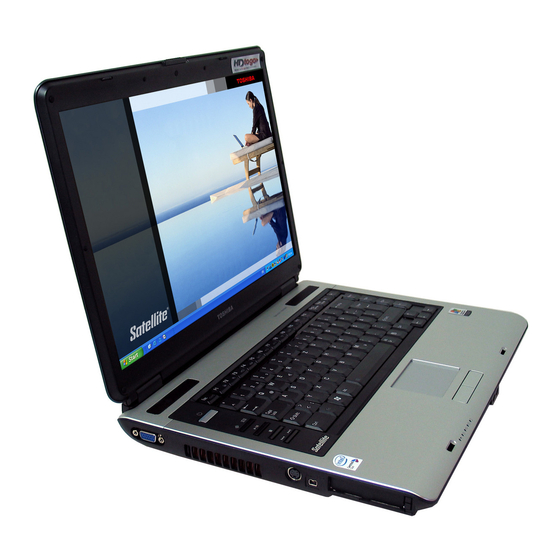
Page 37: Front With The Display Open
The Grand Tour Front with the display open Figure below shows the front of the computer with the display open. To open the display, slide the display latch on the front of the computer and lift the display up. Position the display at a comfortable viewing angle. Display Screen Display Hinge Stereo Speaker... -
Page 38: Av Buttons
The Grand Tour Stereo Speaker The speaker emits sound generated by your software as well as audio alarms, such as low battery condition, generated by the system. Touch Pad Moves the pointer and selects or activates items on the screen. Can be set to perform other mouse functions, such as scrolling, selecting, and double- clicking. -
Page 39: System Indicators
The Grand Tour System indicators Figure below shows the system indicators, which light when various computer operations are in progress. Multiple Digital Media card slot Disk DC IN Power Main battery Systems indicators Power source/system indicators DC IN The DC IN indicator glows blue when DC power is supplied from the AC power adaptor. -
Page 40: Keyboard Indicators
The Grand Tour Keyboard indicators The figures below show the positions of the keypad overlay indicators and the CapsLock indicator. When the F10 key indicator glows the keypad overlay lets you control the cursor. When the F11 key indicator glows the keypad overlay lets you enter numbers. -
Page 41: Usb Diskette Drive
The Grand Tour USB diskette drive A 3 1/2" diskette drive accommodates 1.44-megabyte or 720-kilobyte diskettes. It connects to the USB port. Disk-In-Use Indicator Diskette slot Eject button USB diskette drive Disk-In-Use This indicator lights when the diskette is being Indicator accessed. -
Page 42: Writable Discs
Writable discs This section describes the types of writable CD/DVD discs. Check the specifications for your drive to for the type of discs it can write. Use TOSHIBA Disc Creator to write compact discs. Refer to Chapter 4, Operating Basics. - Page 43 The Grand Tour DVD-ROM drive The full- size DVD-ROM drive module lets you record data to rewritable CD/DVDs as well as run either 12 cm (4.72") or 8 cm (3.15") CD/DVDs without using an adaptor. The read speed is slower at the center of a disc and faster at the outer edge.
- Page 44 The AC adaptor(2-pin plug) The AC adaptor (3-pin plug) Use of the wrong adaptor could damage your computer. TOSHIBA assumes no liability for any damage in such case. The output rating for the computer is 15 volts DC.
-
Page 45: Chapter 3 Getting Started
Chapter 3 Getting Started This chapter provides basic information to get you started using your computer. It covers the following topics: Be sure also to read Instruction Manual for Safety & Comfort. This guide, which is included with the computer, explains product liability. ■... -
Page 46: Connecting The Ac Adaptor
Chapter 6, Power and Power-Up Modes. Use of the wrong adaptor could damage your computer. TOSHIBA assumes no liability for any damage in such case. The output rating for the computer is 15 volts DC. -
Page 47: Turning On The Power
Getting Started When you open the display, hold it with both hands and lift up slowly. Display latch Opening the display panel Turning on the power This section describes how to turn on the power. After you turn on the power for the first time, do not turn it off until you have set up the operating system (OS) and the OS has started up. -
Page 48: Starting Up For The First Time
Getting Started Starting up for the first time When you first turn on the power, the computer’s initial screen is the ® Microsoft Windows Vista™ Startup Screen Logo. Follow the on-screen directions. Turning off the power The power can be turned off in one of the following modes: Shut down (Boot), Hibernation or Sleep mode. -
Page 49: Starting Hibernation
For the computer to shut down in hibernation mode, the hibernation feature must be enabled in two places: the Hibernate tab in Power Options and Setup Action tab in TOSHIBA Power Saver. Otherwise, the computer will shut down in Sleep mode. If battery power becomes depleted, data saved in Sleep mode will be lost. -
Page 50: Sleep Mode
Getting Started Sleep mode In sleep mode the power remains on, but the CPU and all other devices are in sleep mode. 1. Before entering Sleep mode, be sure to save your data. 2. Do not install or remove a memory module while the computer is in sleep mode. -
Page 51: Restarting The Computer
Getting Started Restarting the computer Certain conditions require that you restart the computer system. For example, if: ■ You change certain computer settings. ■ An error occurs and the computer does not respond to your keyboard commands. There are three ways to restart the computer system: 1. -
Page 52: Restoring The Preinstalled Software From The Product Recovery Media
2. Hold down the F12 key and turn on the power. When In Touch with Tomorrow TOSHIBA appears, release the F12 key. 3. Use the cursor keys to select CD/DVD in the display menu. For details, refer to the Boot priority section in Chapter 7, HW Setup and Passwords. -
Page 53: Chapter 4 Operating Basics
Chapter 4 Operating Basics This chapter gives information on basic operations including using the Touch Pad/Dual Mode Pad, USB diskette drive, optical media drives, the microphone, the internal modem, wireless communication and LAN. It also provides tips on caring for your computer, diskettes and CD/DVDs. Using the Touch Pad To use the Touch Pad, simply touch and move your finger tip across it in the direction you want the on-screen pointer to go. -
Page 54: Using The Usb Diskette Drive
Operating Basics Touch Pad Touch Pad Control Buttons Touch Pad and Touch Pad control buttons Using the USB diskette drive A 3 1/2" diskette drive connects to the computer’s USB port. It accommodates 1.44-megabyte or 720-kilobyte diskettes. Refer to Chapter 2, The Grand Tour, for more information. -
Page 55: Using Optical Media Drives
Operating Basics Disconnecting 3 1/2" diskette drive When you have finished using the diskette drive, follow the procedures below to disconnect it: 1. Wait for the indicator light to go out to make sure all diskette activity has stopped. If you disconnect the diskette drive or turn off the power while the computer is accessing the drive you may lose data or damage the diskette or the drive. -
Page 56: Loading Discs
Operating Basics Loading discs To load CD/DVDs, follow the steps below and refer to figures 4-3 to 4-7. 1. a. When the power is on, press the DVD-ROM eject button to open the drawer slightly. Eject button Pressing the DVD-ROM eject button b. - Page 57 Operating Basics 2. Grasp the drawer gently and pull until it is fully opened. Pulling the drawer open 3. Lay the CD/DVD, label side up, in the drawer. Inserting a CD/DVD When the drawer is fully opened, the edge of the computer will extend slightly over the CD/DVD tray.
-
Page 58: Removing Discs
Operating Basics 4. Push the center of the drawer to close it. Press gently until it locks into place. If the CD/DVD is not seated properly when the drawer is closed, the CD/ DVD might be damaged. Also, the drawer might not open fully when you press the eject button. -
Page 59: Av Button Function (Provided With Some Models)
Operating Basics Removing a CD/DVD 3. Push the center of the drawer to close it. Press gently until it locks into place. AV Button function (Provided with some models) This section describes a button function. AV Button Icon AV Button *CD/None CD/DVD Launch WinDVD... -
Page 60: Writing Cds On Cd-Rw/Dvd-Rom Drive
MITSUBISHI CHEMICAL CORPORATION, RICOH Co., Ltd. ■ Ultra-speed CD-RW: MITSUBISHI CHEMICAL CORPORATION TOSHIBA has confirmed the operation of CD-R and CD-RW media of the manufacturers above. Operation of other media cannot be guaranteed. ■ CD-RW can generally be rewritten about 1,000 times. However, the actual number of rewrites is affected by the quality of the media and the way it is used. -
Page 61: When Writing Or Rewriting
Write from the computer’s HDD to the CD. Do not try to write from shared devices such as a LAN server or any other network device. ■ Writing with software other than TOSHIBA Disc Creator has not been confirmed. Therefore, operation with other software cannot be guaranteed. -
Page 62: Writing Cd/Dvds On Dvd Super Multi (+-R Dl) Drive
Based on TOSHIBA’s limited compatibility testing, we suggest the following manufacturers of CD-R/RW and DVD-R/+R/-RW/+RW/-RAM/ +R DL/-R DL disc. ■ However, in no event does TOSHIBA guarantee the operation, quality or performance of any disc. Disc quality can affect write or rewrite success rates. CD-R: TAIYO YUDEN CO., LTD. - Page 63 Operating Basics DVD+R MITSUBISHI KAGAKU MEDIA CO., LTD Ricoh Co., Ltd. DVD-RW DVD Specifications for Recordable Disc for Version 1.1 VICTOR COMPANY OF JAPAN, LIMITED MITSUBISHI KAGAKU MEDIA CO., LTD DVD+RW MITSUBISHI KAGAKU MEDIA CO., LTD Ricoh Co., Ltd. DVD-RAM DVD Specifications for DVD-RAM Disc for Version 2.0, Version 2.1 or Version 2.2 Matsushita Electric Industrial Co., Ltd.
- Page 64 Write from the computer’s HDD to the CD/DVD. Do not try to write from shared devices such as a LAN server or any other network device. ■ Writing with software other than TOSHIBA Disc Creator is not recommended. When writing or rewriting Please observe/consider the following when you write or rewrite to a CD-R/ RW, DVD-R/-R DL/-RW/-RAM or DVD+R/+R DL/+RW disc.
-
Page 65: Toshiba Disc Creator
CD Player" function to record music to the DVD-R/-R DL/-RW or DVD+R/+R DL/+RW disc. ■ Do not use the "Exact Copy" function of TOSHIBA Disc Creator to copy DVD-Video and DVD-ROM with copyright protection. ■ DVD-RAM disc cannot be backed up with the "Exact Copy" function of TOSHIBA Disc Creator. -
Page 66: Data Verification
DVD drive with the disc loaded is unable to be ejected even the "Eject" button is pressed. To solve this problem, please click on the "eject" button ( ) on the TOSHIBA Disc Creator main screen, or right click on the icon of the DVD drive where the disc loaded, select "Eject"... -
Page 67: When Using Ulead Dvd Moviefactory® For Toshiba
Simplified steps for making a DVD-Video from video data captured from a DV-Camcorder: 1. Click - All Programs - DVD MovieFactory for TOSHIBA - Ulead DVD MovieFactory for TOSHIBA Launcher to launch DVD MovieFactory. 2. Insert a DVD-RW or DVD+RW disc in Burner. - Page 68 Operating Basics ■ Do not operate DVD MovieFactory immediately after turning on the computer. Please wait until all Disc Drive activity has stopped. ■ When recording to a DV-Camcorder, to ensure you capture all of your data, let the camcorder record for a few seconds before you begin recording your actual data.
-
Page 69: Media Care
Operating Basics Media care This section provides tips on protecting data stored on your CD/DVDs and diskettes. Handle your media with care. The following simple precautions will increase the lifetime of your media and protect the data stored on them: CD/DVDs 1. -
Page 70: Modem (Provided With Some Models)
To select a region, follow the steps below. 1. In Windows Vista™, click , point to All Programs, point to TOSHIBA, point to Networking and click Modem Region Select Utility. Do not use the Country/Region Select function in the Modem setup utility in the Control Panel if the function is available. -
Page 71: Properties Menu
Operating Basics Properties menu Click the icon with the secondary mouse button to display the following menu. The menu list (Windows Vista™) Setting You can enable or disable the following settings: AutoRun Mode The Region Select utility starts automatically when you start up the operating system. -
Page 72: Wireless Communications
Operating Basics Connecting To connect the internal modem cable, follow the steps below. 1. Plug one end of the modular cable into the modem jack. 2. Plug the other end of the modular cable into a telephone jack. Telephone Jack Modem Jack Connecting the internal modem Do not pull on the cable or move the computer while the cable is... -
Page 73: Bluetooth Wireless Technology
TOSHIBA strongly recommends the customer to enable the WEP function. ■ TOSHIBA is not liable for the eavesdropping of data due to the use of Wireless LAN and the damage thereof. Bluetooth wireless technology Bluetooth™ wireless technology eliminates the need for cables between electronic devices such as desktop computers, printers and mobile phones. -
Page 74: Lan
Operating Basics Wireless communication switch You can enable or disable Wireless LAN and Bluetooth functions, with the on/off switch. No transmissions are sent or received when the switch is off. Slide the switch toward the left of the computer to turn it on and toward the right of the computer to turn it off. -
Page 75: Connecting Lan Cable
Operating Basics Connecting LAN cable The computer must be configured properly before connecting to a LAN. Logging onto a LAN using the computer’s default settings could cause a malfunction in LAN operation. Check with your LAN administrator regarding set-up procedures. If you are using Fast Ethernet LAN (100 megabits per second, 100BASE-TX), be sure to connect with a category 5 cable, CAT5, or higher. -
Page 76: Cleaning The Computer
Operating Basics Cleaning the computer To help ensure long, trouble-free operation, keep the computer free of dust and use care with liquids around the computer. ■ Be careful not to spill liquids into the computer. If the computer does get wet, turn the power off immediately and let the computer dry completely before you turn it on again. -
Page 77: Heat Dispersal
CPU speed. Or, by lowering the CPU speed first, then if necessary, turning on the fan. Use the Cooling Method item of the Basic Setup window in TOSHIBA Power Saver. When the CPU temperature falls to a normal range, the fan is turned off and the CPU operation returns to standard speed. -
Page 78: Chapter 5 The Keyboard
Chapter 5 The Keyboard The computer’s keyboard layouts are compatible with a 101/102-key enhanced keyboard. By pressing some keys in combination, all the 101/ 102-key keyboard functions can be executed on the computer. The number of keys on your keyboard depends on which country/region’s keyboard layout your computer is configured with. -
Page 79: F1 ... F12 Function Keys
Soft keys: Fn key combinations The Fn (function) is unique to Toshiba computers and is used in combination with other keys to form soft keys. Soft keys are key combinations that enable, disable or configure specific features. -
Page 80: Hot Keys
The Keyboard Press Fn + Enter to simulate Enter on the enhanced keyboard’s numeric keypad. Press Fn + Ctrl to simulate the enhanced keyboard’s right Ctrl key. Press Fn + Alt to simulate the enhanced keyboard’s right Alt key. Hot keys Hot keys (Fn + a function or Esc key) let you enable or disable certain features of the computers. - Page 81 The Keyboard Display selection: Press Fn + F5 to change the active display device. When you press these hot keys a dialog box appears. Only selectable devices will be displayed. Hold down Fn and press F5 again to change the device.
-
Page 82: Windows Special Keys
Fn key. Fn Sticky key You can use the Toshiba Accessibility Utility to make the Fn key sticky, that is, you can press it once, release it, and they press an "F number" key. To start the Toshiba Accessibility Utility, click , point to All Programs, point to TOSHIBA, point to Utilities and click Accessibility. -
Page 83: Arrow Mode
The Keyboard Arrow mode To turn on the Arrow mode, press Fn + F10. The Arrow mode indicator lights. Now try cursor and page control using the keys shown in figure above. Press Fn + F10 again to turn off the overlay. Numeric mode To turn on the Numeric mode, press Fn + F11. -
Page 84: Generating Ascii Characters
The Keyboard Temporarily using overlay (overlay off) While using the normal keyboard, you can temporarily use the keypad overlay without turning it on: 1. Press and hold down Fn. 2. Check the keyboard indicators. Pressing Fn turns on the most recently used overlay. -
Page 85: Chapter 6 Power And Power-Up Modes
Chapter 6 Power and Power-Up Modes The computer’s power resources include the AC adaptor and internal batteries. This chapter gives details on making the most effective use of these resources including charging and changing batteries, tips for saving battery power, and power up modes. Power conditions The computer’s operating capability and battery charge status are affected by the power conditions: whether an AC adaptor is connected, whether a... -
Page 86: Power Indicators
• LED: Battery trigger point flashes Amber DC IN off Battery charge is Computer goes into exhausted Hibernation or shuts down (depending on the Toshiba power Management Utility Setting) No battery • No operation installed • LED: Battery off DC IN off... -
Page 87: Battery Types
Dispose of the battery as required by local ordinances or regulations. Use only batteries recommended by TOSHIBA as replacements. The battery recharges the RTC batteries. The battery maintains the state of the computer when you enable Resume. -
Page 88: Care And Use Of The Battery Pack
Check system. Then press [F1] key . . . The computer’s RTC battery is a lithium ion battery and should be replaced only by your dealer or by a TOSHIBA service representative. The battery can explode if not properly replaced, used, handled or disposed of. - Page 89 Never use the computer again until it has been checked by a TOSHIBA service provider. It might generate smoke or fire, or the battery pack might rupture. User’s Manual...
- Page 90 2. Never dispose of battery packs with normal trash. Bring them to your TOSHIBA dealer or to another recycling center to save resources and prevent environmental damage. Cover the terminals with electrical tape to prevent short-circuits, which could cause the battery pack to ignite or rupture.
-
Page 91: Charging The Batteries
The Battery indicator glows amber when the battery is being charged. Use only the computer connected to an AC power source or the optional TOSHIBA Batteries charger to charge the battery pack. Never attempt to charge the battery pack with any other charger. -
Page 92: Monitoring Battery Capacity
Therefore, an often used, older battery will not operate for as long as a new battery even when both are fully charged. In this case, TOSHIBA Power Saver will indicate a 100% charge for both the old and new battery, but the displayed estimated time remaining will be shorter for the older battery. -
Page 93: Extending Battery Life
Power and Power-Up Modes ■ Screen brightness ■ Cooling Method ■ System Sleep ■ System Hibernation ■ Monitor Power off ■ HDD Power off ■ How often and how long you use the hard disk, CD/DVD-ROM drive and the diskette drive. ■... -
Page 94: Replacing The Battery Pack
Power and Power-Up Modes 3. Operate the computer on battery power for five minutes. If the battery pack has at least five minutes of operating time, continue operating until the battery pack is fully discharged. If the battery LED flashes or there is some other warning to indicate a low battery, go to step 4. - Page 95 Battery Release Latch Battery Pack Removing the battery pack 7. Pull the battery pack forward to remove it. For environmental reasons, do not throw away a spent battery pack. Please return spent battery pack to your TOSHIBA dealer. User’s Manual 6-11...
-
Page 96: Starting The Computer By Password
Dispose of the battery as required by local ordinances or regulations. Use only batteries recommended by TOSHIBA as replacements. 1. Be sure the computer’s power is off and all cables are disconnected. 2. Insert the battery pack. -
Page 97: Power-Up Modes
Chapter 3, Getting Started. Windows utilities You can specify the setting in TOSHIBA Power Saver. Hot keys You can use hot keys Fn + F3 to enter Sleep mode and Fn + F4 to enter Hibernation. See Chapter 5, The Keyboard for details. -
Page 98: Chapter 7 Hw Setup And Passwords
CPU, boot priority, keyboard, USB, LAN, general, password, and device config. If the supervisor password is set, access to the TOSHIBA HW Setup program can be prevented when the user password is used to log on to the computer. -
Page 99: User Password
HW Setup and Passwords General This window displays the BIOS version and contains two buttons: Default and About. Return all HW Setup values to the factory settings. Default Display the HW Setup version. About Setup This field displays BIOS Version and date. -
Page 100: Power On Display
HW Setup and Passwords 2. Enter the currently registered password. The character string you enter is displayed as a string of asterisks. Enter Password: **** Registered If you click the OK button before entering the password, will appear on the display. 3. -
Page 101: Boot Priority
HW Setup and Passwords Boot Priority Boot Priority Options This option sets the priority for booting the computer. You can override the settings and manually select a boot device by pressing one of the following keys while the computer is booting: Selects the USB diskette drive. -
Page 102: Legacy Usb Support
HW Setup and Passwords Keyboard Wake-up on Keyboard When this feature is enabled and the computer is in sleep mode, you can turn on the computer by pressing any key. It is effective only for the internal keyboard and only when the computer is in sleep mode. Enables Wake-up on Keyboard. -
Page 103: Chapter 8 Optional Devices
Chapter 8 Optional Devices Optional devices can expand the computer’s capabilities and its versatility. The following optional devices are available from your TOSHIBA dealer: Cards/memory ■ PC cards ■ SD, MS, MS Pro, MMC, xD memory cards ■ Memory expansion depending on the model purchased ■... -
Page 104: Pc Cards
The computer is equipped with a PC card expansion slot that can accommodate one 5 mm Type II card. Any PC card that meets industry standards (manufactured by TOSHIBA or other vendor) can be installed. The slots support 16-bit PC cards, including PC card 16’s multifunction card and CardBus PC cards. -
Page 105: Express Card
Optional Devices Removing a PC card To remove the PC card, follow the steps below. 1. In Windows Vista™, open the Safely Remove Hardware icon on the system tray and disable the PC card. 2. Press the eject button of the PC card you want to remove to extend the button. -
Page 106: Removing An Express Card
Optional Devices 3. Check the configuration in the HW Setup window to make sure it is appropriate for your card. Express Card slot Inserting the Express Card Removing an Express Card To remove the Express Card, follow the steps below. 1. -
Page 107: Multiple Digital Media Card Slot
Optional Devices Multiple Digital Media Card Slot The computer is equipped with a Multiple Digital Media Card Slot that can accommodate Secure Digital (SD)/Memory Stick (MS)/Memory Stick Pro (MS Pro)/Multi Media Card (MMC)/xD memory cards. These memory cards let you easily transfer data from devices, such as digital cameras and Personal Digital Assistants, that use SD/MS/MS Pro/MMC/xD memory cards. - Page 108 Optional Devices Make sure the SD/MS/MS Pro/MMC/xD card is oriented properly before you insert it. ■ Memory Stick Duo/Memory Stick Pro Duo/Mini SD card is not supported. ■ Two kinds of cards will not work at the same time. Please insert only one card when using Multiple Digital Media Card Slot.
-
Page 109: Memory Expansion
Optional Devices Memory expansion You can install additional memory in the computer’s memory module to increase the amount of RAM. Only memory modules with the following parts numbers can be installed: ■ 256MB: PA3389U-1M25 ■ 512MB: PA3412U-1M51 ■ 1GB: PA3411U-1M1G Installing memory module To install a memory module, make sure the computer is in boot mode then: 1. - Page 110 Optional Devices Removing the cover 6. Insert the memory module into the connector on the computer. Press the module carefully and firmly to ensure a solid connection. 7. Push the module down so that it lies flat and is secured by two latches. Do not touch the connectors on the memory module or on the computer.
-
Page 111: Removing Memory Module
Optional Devices Removing memory module To remove the memory module, make sure the computer is in boot mode then: 1. Turn the computer off and remove all cables connected to the computer. ■ If you use the computer for a long time, the memory modules will become hot. -
Page 112: Additional Battery Pack (6 Cell, 9 Cell And 12 Cell)
Optional Devices Additional battery pack (6 Cell, 9 Cell and 12 Cell) You can increase the portability of the computer with additional battery packs (6 Cell: PA3399U-2BAS/PA3399U-2BRS, 9 Cell: PA3478U-1BAS/ PA3478U-1BRS, 12 Cell: PA3400U-1BAS/PA3400U-1BRS). If you’re away from an AC power source, you can replace a low battery with a fully charged one. -
Page 113: Television
Optional Devices If you have selected Simultaneous under the Display options of the HW Setup, both the external monitor and the internal LCD will be active when you turn on the computer. If Auto-Selected is selected, only the external monitor will be active. To change the display settings, press Fn + F5. - Page 114 There is a possibility that the original data will be damaged. There is a particular risk that some frames will be deleted in the case of digital video transfer. TOSHIBA assumes no liability for such loss of data. 2. Do not transfer data in areas where static electricity is easily generated or in areas subjected to electronic noise.
-
Page 115: Security Lock
Optional Devices Disconnecting 1. Open the Safety Remove Hardware icon on the Task Bar. 2. Point to i.LINK (IEEE1394) device and click. 3. Disconnect the cable from the computer then from the i.LINK device. Refer also to the documentation that came with your i.LINK device. Security lock A security lock enables you to anchor your computer to a desk or other heavy object to help prevent unauthorized removal of the computer. -
Page 116: Troubleshooting
Chapter 9 Troubleshooting TOSHIBA designed the computer for durability. However, should problems occur, following the procedures in this chapter can help to determine the cause. All readers should become familiar with this chapter. Knowing what might go wrong can help prevent problems from occurring. -
Page 117: Analyzing The Problem
Troubleshooting ■ Make sure all options are set properly in the setup program. ■ Check all cables. Are they correctly and firmly attached? Loose cables can cause signal errors. ■ Inspect all connecting cables for loose wires and all connectors for loose pins. -
Page 118: Hardware And System Checklist
When the computer starts up, the self-test will be run automatically, and the following will be displayed: In Touch with Tomorrow TOSHIBA This message remains on the screen for a few seconds. If the self test is successful, the computer tries to load the operating system. -
Page 119: Overheating Power Down
Troubleshooting Turn off the computer and check all cable connections. If the test fails again, contact your dealer. Power When the computer is not plugged into an AC adaptor, the battery pack is the primary power source. However, your computer has a number of other power resources, including intelligent power supply and Real Time Clock battery. - Page 120 Troubleshooting Battery If you suspect a problem with the battery, check the DC IN indicator as well as the battery indicator. For information on indicators and battery operation see Chapter 6, Power and Power-Up Modes. Problem Procedure Battery doesn’t The battery may be discharged. Connect the power the computer AC adaptor to charge the battery.
-
Page 121: Lcd Panel
Troubleshooting Keyboard Keyboard problems can be caused by your setup configuration. For more information refer to Chapter 5, The Keyboard and Chapter 7, HW Setup Passwords. Problem Procedure Some letter keys Check that the numeric keypad overlay is not produce numbers selected. - Page 122 Troubleshooting Problem Procedure Slow performance Your files may be fragmented. Run SCANDISK and defragmenter to check the condition of your files and disk. Refer to your OS documentation or online HELP for information on running SCANDISK and the defragmenter. As a last resort, reformat the hard disk. Then, reload the operating system and other files.
- Page 123 Troubleshooting CD-RW/DVD-ROM drive For more information, refer to Chapter 4, Operating Basics. Problem Procedure You cannot access a Make sure the drive’s drawer is securely closed. CD/DVD in the drive Press gently until it clicks into place. Open the drawer and make sure the CD/DVD is properly seated.
- Page 124 Cannot write If you have trouble writing, make sure you are correctly observing the following precautions: ■ Use only media recommended by TOSHIBA ■ Do not use the mouse or keyboard during writing. ■ Use only the software supplied with the computer for recording.
- Page 125 Cannot write If you have trouble writing, make sure you are correctly observing the following precautions: ■ Use only media recommended by TOSHIBA ■ Do not use the mouse or keyboard during writing. ■ Use only the software supplied with the computer for recording.
-
Page 126: Diskette Drive
Troubleshooting Diskette drive For more information, refer to Chapter 4, Operating Basics. Problem Procedure Drive does not There may be a faulty cable connection. Check the operate connection to the computer and to the drive. Some programs run The software or hardware configuration may be correctly but others causing a problem. - Page 127 Troubleshooting Problem Procedure When the reaction Adjust the touch Sensitivity. of Touch pad is 1. Open the Control Panel. sensitive to slow 2. Click the Printers icon and then the Other Hardware icon. 3. Click the Mouse icon. 4. Click the Device Setting tab. 5.
- Page 128 Troubleshooting Problem Procedure The mouse pointer The mouse might be dirty. Refer to your mouse moves erratically documentations for instructions on cleaning. If problems persist, contact your dealer. PC card Refer also to Chapter 4, Operating Basics. Problem Procedure PC card error Reseat the PC card to make sure it is firmly occurs connected.
-
Page 129: Sound System
Troubleshooting Problem Procedure Display error occurs Check that the cable connecting the external monitor to the computer is attached firmly. If problems persist, contact your dealer. Sound system Problem Procedure No sound is heard Adjust the volume control dial. Check the software volume settings. Make sure the headphone connection is secure. - Page 130 Troubleshooting Refer also to your USB device’s documentation. Problem Procedure USB device does Check for a firm cable connection between the not work USB ports on the computer and the USB device. Make sure the USB device drivers are properly installed.
- Page 131 Troubleshooting Problem Procedure A CONNECT display Check the error control setting in your is quickly replaced communications application. by NO CARRIER You can also use the AT\N command. Refer to the chapter on AT commands in online help files for Appendix C, Commands.
- Page 132 Troubleshooting Wireless LAN If the following procedures do not restore LAN access, consult your LAN administrator. For more information on wireless communication, refer to Chapter 4, Operating Basics. Problem Procedure Cannot access Make sure the computer’s wireless communication Wireless LAN switch is set to on.
-
Page 133: Toshiba Support
Troubleshooting TOSHIBA support If you require any additional help using your computer or if you are having problems operating the computer, you may need to contact TOSHIBA for additional technical assistance. Before you call Some problems you experience may be related to software or the operating system, it is important to investigate other sources of assistance first. - Page 134 Chapter 10 Disclaimers This chapter slates the Disclaimer(s) information applicable to TOSHIBA computers. Central Processing Unit ("CPU") Performance Disclaimer. CPU performance in your computer product may vary from specifications under the following conditions: ■ use of certain external peripheral products ■...
-
Page 135: Main Memory Disclaimer
This is a normal phenomenon for all batteries. To purchase a new battery pack, see the accessories information that is shipped with your computer, or visit the Toshiba web site at www.pcsupport.toshiba.com User’s Manual... -
Page 136: Hdd Drive Capacity
Disclaimers HDD Drive Capacity 1 Gigabyte (GB) means 10 = 1,000,000,000 bytes using powers of 10. The computer operating system, however, reports storage capacity using powers of 2 for the definition of 1 GB = 2 = 1,073,741,824 bytes, and therefore shows less storage capacity. -
Page 137: Lcd Brightness And Eye Strain
Disclaimers SRS audio enhancements are available in the Microsoft Windows operation system only. LCD Brightness and Eye Strain Your LCD display has a brightness approaching that of a TV device. We recommend that you adjust the brightness of your LCD to a comfortable level to prevent possible strain on your eyes. -
Page 138: Specifications
Appendix A Specifications This appendix summarizes the computer’s technical specifications. Physical Dimensions Size With TFT display 360 (w) × 267 (d) × 29.8 (front) / 36.8 (rear) millimeters Weight (typical*) < 3 kilograms, configured with: 15.4" panel, DVD Combo drive, 6-cell battery, and modem. * Weight will vary depending on whether or not and what kind of options are adopted. -
Page 139: Power Requirements
Specifications Power Requirements AC adaptor 100- 240 volts AC 50 or 60 hertz (cycles per second) Computer 15 VDC 5.0 amperes/6.0 amperes Built-in Modem The ability of this feature is depending on the model you purchased. Network control unit (NCU) Type of NCU Type of line Telephone line (analog only) - Page 140 Specifications Communication Data transmission and reception speed 300/1200/2400/4800/7200/9600/12000/14400/ 16800/19200/21600/24000/26400/28800/31200/ 33600 bps Data reception only with V.90 28000/29333/30666/32000/33333/34666/36000/ 37333/38666/40000/41333/42666/44000/45333/ 46666/48000/49333/50666/52000/53333/54666/ 56000 bps 2400/4800/7200/9600/12000/14400 bps Error correcting MNP class 4 and ITU-T V.42 Data compression MNP class 5 and ITU-T V.42bis User’s Manual...
-
Page 141: Appendix B Display Controller And Modes
Appendix B Display Controller and Modes Display controller The display controller interprets software commands into hardware commands that turn particular pels on or off. The controller is an advanced Video Graphics Array (VGA) that provides Super VGA (SVGA) and Extended Graphics Array (XGA) support for the internal LCD and external monitors. -
Page 142: Video Modes
Display Controller and Modes Video Modes The computer supports video modes defined in the table below. If your application offers a selection of mode numbers that do not match the numbers on the table, select a mode based on, resolution, number of colors and refresh rates. - Page 143 Appendix C V.90/V.92 The TOSHIBA internal modem uses V.90 technology. The modem is capable of downstream speeds of 56Kbps (kilobits per second) when connected to an Internet service provider that supports V.90/V.92. As with any modem, the actual throughput (speed of data transfer) depends on analog telephone line conditions, which can vary considerably.
- Page 144 V.90/V.92 Result codes for a V.90 connection Result code Description CONNECT 32000 EC* Connection at 32000 bits/s CONNECT 36000 EC* Connection at 36000 bits/s CONNECT 40000 EC* Connection at 40000 bits/s CONNECT 44000 EC* Connection at 44000 bits/s CONNECT 48000 EC* Connection at 48000 bits/s CONNECT 52000 EC* Connection at 52000 bits/s...
- Page 145 V.90/V.92 AT Commands -V90=* V.90 Dial Line Rate -V90 sets the maximum V.90 downstream that the modem attempts to connect. -V90=0 V.90 disabled -V90=1 V.90 enabled: automatic speed selection - maximum modem speed (default) User’s Manual...
-
Page 146: Wireless Lan
Appendix D Wireless LAN This appendix is intended to help you get your Wireless LAN network up and running, with a minimum of parameters. Card specifications ■ From Factor Mini Card ■ Compatibility IEEE 802.11 Standard for Wireless LANs ■ Wi-Fi (Wireless Fidelity) certified by the Wi-Fi Alliance. -
Page 147: Radio Characteristics
Subject to the radio regulations that apply in your country/region, your Wireless LAN card may support a different set of 5 GHz/2.4 GHz channels. Consult your Authorized Wireless LAN or TOSHIBA Sales office for information about the radio regulations that apply in your country/region. - Page 148 Wireless LAN Wireless IEEE 802.11 Channels Sets (Revision B and G) Frequency Range Channel ID 2400-2483.5 MHz 2412 2417 2422 2427 2432 2437 2442 2447 2452 2457* 2462 2467 2472 When installing Wireless LAN cards, the channel configuration is managed as follows: ■...
- Page 149 Wireless LAN Wireless IEEE 802.11 Channels Sets (Revision A) Frequency Range Channel ID 5150-5850 MHz Note 5180 5200 5220 5240 5260 5280 5300 5320 5500 5520 5540 5560 5580 5600 5620 5640 5660 5680 5700 5745 US only 5765 US only 5785 US only 5805...
-
Page 150: Ac Power Cord And Connectors
Appendix E AC Power Cord and Connectors The power cord’s AC input plug must be compatible with the various international AC power outlets and the cord must meet the standards for the country/region in which it is used. All cords must meet the following specifications: Length: Minimum 1.7 meters... - Page 151 AC Power Cord and Connectors In Europe, two conductors power cord must be VDE type, H05VVH2-F or H03VVH2-F and for three conductors power cord must be VDE type, H05VV-F. For the United States and Canada, two pin plug configuration must be a 2-15P (250V) or 1-15P (125V) and three pin plug configuration must be 6-15P (250V) or 5-15P (125V) as designated in the U.S.
-
Page 152: If Your Computer Is Stolen
What is your address, phone, and fax number? To register the theft on paper, please follow these procedures: ■ Fill in the TOSHIBA Theft Registration form (or a copy of it) below. ■ Attach a copy of your receipt showing where your computer was purchased. -
Page 153: Toshiba Theft Registration
TOSHIBA Europe GmbH Technical Service and Support Leibnizstr. 2 93055 Regensburg Germany Fax number: +49 (0) 941 7807 921 Country stolen: Machine type: (e.g. TOSHIBA A100) Model number: (e.g. PSA30 YXT) Serial number: (e.g. 12345678G) Date stolen: Year Month Owner’s details... - Page 154 Glossary The terms in this glossary cover the topics discussed in this manual. Alternate naming is included for reference. Abbreviations AC: alternating current AGP: accelerated graphics port ANSI: American National Standards Institute APM: advanced power manager ASCII: American Standard Code for Information Interchange BIOS: basic input output system CMOS: complementary metal-oxide semiconductor CPU: central processing unit...
- Page 155 Glossary HDD: hard disk drive IDE: integrated drive electronics I/O: input/output IrDA: Infrared Data Association IRQ: interrupt request KB: kilobyte LCD: liquid crystal display LED: light emitting diode LSI: large scale integration MDA: monochrome display adapter MPEG: moving picture coding experts group MS-DOS: Microsoft Disk Operating System OCR: optical character recognition (reader) PCB: printed circuit board...
- Page 156 Glossary adapter: A device that provides an interface between two dissimilar electronic devices. For example, the AC adapter modifies the power from a wall outlet for use by the computer. This term also refers to the add-in circuit cards that control external devices, such as video monitors and magnetic tape devices.
- Page 157 Glossary BIOS: Basic Input Output System. The firmware that controls data flow within the computer. See also firmware. bit: Derived from ìbinary digit,î the basic unit of information used by the computer. It is either zero or one. Eight bits is one byte. See also byte.
- Page 158 Glossary CGA: Color/graphics adapter. A video display protocol defined by the IBM Color/Graphics Monitor Adapter and its associated circuitry. This protocol supports two-color 640 × 200 and four-color 320 × 200 graphics, and 16-color 640 × 200 and 320 × 200 text modes. character: Any letter, number, punctuation mark, or symbol used by the computer.
- Page 159 Glossary CPS: Characters per second. Typically used to indicate the transmission speed of a printer. CPU: Central processing unit. The portion of the computer that interprets and executes instructions. CRT: Cathode Ray Tube. A vacuum tube in which beams projected on a fluorescent screen-producing luminous spots.
- Page 160 Glossary driver: A software program, generally part of the operating system, that controls a specific piece of hardware (frequently a peripheral device such as a printer or mouse). echo: To send back a reflection of the transmitted data to the sending device.
- Page 161 Fn, can be used to set system parameters, such as speaker volume. HW Setup: A TOSHIBA utility that lets you set the parameters for various hardware components. I/O devices: Equipment used to communicate with the computer and transfer data to and from it.
- Page 162 Glossary input: The data or instructions you provide to a computer, communication device or other peripheral device from the keyboard or external or internal storage devices. The data sent (or output) by the sending computer is input for the receiving computer. instruction: Statements or commands that specify how to perform a particular task.
- Page 163 Glossary main board: See motherboard. MDA: Monochrome Display Adapter. A video display protocol defined by the IBM Monochrome Display Adapter and its associated circuitry for direct drive TTL displays that supports a monochrome 720 × 350 text mode. megabyte (MB): A unit of data storage equal to 1024 kilobytes. See also kilobyte.
- Page 164 Glossary OCR wand: A device that reads, using an optical device, hand written or machine printed symbols into a computer. See also OCR. OCR: Optical Character Recognition (reader). A technique or device that uses laser or visible light to identify characters and input them into a storage device.
- Page 165 A Class A device is sufficient for office use. Class B provides a more stringent classification for home equipment use. TOSHIBA portable computers comply with Class B computing device regulations. Random Access Memory (RAM): High speed memory within the computer circuitry that can be read or written to.
- Page 166 Glossary serial interface: Refers to a type of information exchange that transmits information sequentially, one bit at a time. Contrast: Parallel interface. serial port: A communications port to which you can connect devices, such as a modem, mouse, or serial printer. serial: The handling of data bits one after the other.
- Page 167 Glossary VGA: Video graphics array is an industry standard video adapter that lets you run any popular software. volatile memory: Random access memory (RAM) that stores information as long as the computer is connected to a power source. Warm dock/undock: Connecting or disconnecting a device to or from the computer while the computer is suspended.
- Page 168 Index AC adaptor, 1-6, 2-5 DC IN indicator, 2-9, 6-3 DC IN 15V port, 2-5 Disk indicator, 2-9 additional, 1-14, 8-10 Display, 1-5, 2-7 connecting, 3-2 automatic power off, 1-9 ASCII characters, 5-7 opening, 3-2 Auto power on, See Power See also Video modes and Monitor external...
- Page 169 Index Fn + Esc (Sound mute), 5-3 Fn + F1 (lock computer mode), 5-3 Keyboard, 1-6, 5-1 Fn + F2 (power save mode), 5-3 emulating enhanced Fn + F3 (sleep), 5-3 keyboard, 5-2 Fn + F4 (hibernation), 5-3 F1 ... F12 function keys, 5-2 Fn + F5 (display selection), 5-4 problems, 9-6 Fn + F6 (display brightness), 5-4...
- Page 170 9-1 with, 6-12 self test, 9-3 user, 7-2 sleep/hibernation, 9-16 PC card, 1-7 sound system, 9-14 installing, 8-2 support from TOSHIBA, 9-18 location of slots, 2-2 TV output signal, 9-14 problems, 9-13 USB, 9-15 removing, 8-3 Wireless LAN, 9-17 Ports...
- Page 171 ScrLock, 5-2 Sound system, 1-7 headphone, 1-6, 2-2 microphone, 1-6, 2-1 problems, 9-14 speaker, 2-8 volume control, 2-1 TOSHIBA Power Saver, 1-11 TOSHIBA Theft Registration, F-2 TV, 8-11 Utilities and Application list, 1-12 USB, 1-6 location, 2-4, 2-5 problems, 9-15...