Panasonic Panaboard UB-5310 Operating Instructions Manual
Electronic board
Hide thumbs
Also See for Panaboard UB-5310:
- Operating instructions manual (48 pages) ,
- Installation manual (20 pages) ,
- Brochure & specs (2 pages)
Table of Contents
Advertisement
Quick Links
Download this manual
See also:
Installation Manual
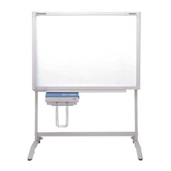
[Stand (option)]
Stand kit is optional.
• To assemble this unit, please refer to the Installation Manual.
• Before operating this unit, please read these instructions completely and keep them carefully for future reference.
• This product is designed for installation by a qualified servicing dealer.
Installation performed by non-authorized individuals could cause safety-related problems with the operation of
this equipment.
• To locate the closest authorized dealer in your area, please call 1-800-449-8989.
(for qualified service personnel)
[Wall-mounting]
Electronic Board
Operating Instructions
With Installation Manual
Model No.
UB-5310
Advertisement
Chapters
Table of Contents

Related Manuals for Panasonic Panaboard UB-5310


Summary of Contents for Panasonic Panaboard UB-5310
-
Page 1: Operating Instructions
Installation performed by non-authorized individuals could cause safety-related problems with the operation of this equipment. • To locate the closest authorized dealer in your area, please call 1-800-449-8989. Electronic Board Operating Instructions With Installation Manual (for qualified service personnel) Model No. UB-5310... - Page 2 • Power cord ....1 * The stand is optional. By way of example, this manual describes an Electronic Board which is used with the stand.
-
Page 3: Table Of Contents
Table of Contents For Your Safety........4 Before Precautions . -
Page 4: For Your Safety
For Your Safety CAUTION: TO PREVENT RISK OF ELECTRIC SHOCK HAZARD, DO NOT REMOVE THE COVER OF THIS PRODUCT, REFER SERVICING TO QUALIFIED SERVICE PERSONNEL. WARNING: TO PREVENT FIRE OR SHOCK HAZARD, DO NOT EXPOSE THIS PRODUCT TO RAIN OR ANY TYPE OF MOISTURE. -
Page 5: Precautions
Push to lock Locking the casters (Push this side) If the electronic board is not going to be used for an extended period of time (e.g., during extended holidays), turn off the power and remove the plug from the wall outlet. -
Page 6: Cd-Rom
Precautions Do not lean against the screen or on the cover (lower), even if the electronic board is mounted on the wall. Confirm both sides of the screen are hung in the same height slots. Slot 3 Slot 2 Slot 1 ■... - Page 7 USB Cable • Use a shielded USB cable that is certified as logo by USB-IF. • If you connect the electronic board to a USB hub, it is not guaranteed to work. Precautions 25 mm (1 " ) 0 mm 12.5 mm...
-
Page 8: Part Names And Functions
Part Names and Functions Scanner Printer Output Port USB Connector (See page 16.) Printer Door Open this door to load copy paper or to remove jammed paper. (See pages 10, 13.) Copied Paper Holder This holder holds up to 5 sheets of output paper. -
Page 9: Control Panel
■ Control panel Contrast Indicator Contrast Key 2-Screen Copy Key Panel Name Contrast Indicator Contrast 2-Screen Copy Key Multi-Copy/ Error Indicator Multi-Copy/ Stop Key Copy Key Advance Advance Key Copy Key Description This lamp indicator displays the printing contrast used during copying. -
Page 10: Loading Copy Paper
Loading Copy Paper Door Open Button Load a new roll when: • Red bands become visible at the edge of the copy paper. • The ERROR indicator “ ” goes on and off even after the printer door is closed properly. Turn the power switch on by pressing the “... -
Page 11: Making Copies
Making Copies This section describes how to copy text and illustrations drawn on the screen. Output paper Turn the power switch on by pressing the “ I ” side of the power switch. • The unit is ready for use when “ Power multi-copy/error indicator. -
Page 12: Copy Types And Procedures
Making Copies ■ Copy types and procedures Copy Type Copying the front of the screen Copying the back of the screen Making multiple copies (up to 9) Making 2-screen copies • Copying the front and back of the screen on a single sheet of paper Copying chart paper... -
Page 13: Paper Jams
Paper Jams To release jammed paper: Slot B Cutter cover Push the door open button and open the printer door. Door Open Button Remove the jammed paper by pulling the paper roll to the direction A. If the jammed paper is still in the cutter cover, remove it using tweezers from slot B. -
Page 14: Screen Height Adjustment
Screen Height Adjustment The screen can be adjusted at 3 levels except for the lowest level. The lowest level of the board attachment frame is designed for installation of the screen, so the printer cannot be attached at this level. Adjust the level of the screen unit as follows. - Page 15 Height adjustment handles Step frame Board attachment (upper) Screen Height Adjustment Tighten the height adjustment handles. Height Be sure to tighten the height adjustment handles adjustment handles firmly after adjusting the level of the screen. Store the step frame by hanging it on the board attachment (upper).
-
Page 16: Computer Interfacing
* If you connect the electronic board to a USB hub, it is not guaranteed to work. * Please note that if more than one Panasonic electronic boards are connected in a USB tree, only one of those electronic boards will perform the computer interfacing. -
Page 17: Installing The Driver And Software
Installing the USB and Printer driver Windows 98 Power on your computer and start Windows. Power on the electronic board, and connect the unit and your computer with a USB cable. When “USB Composite Device” is detected, click the [Next] button. - Page 18 Computer Interfacing Windows Me Power on your computer and start Windows. Power on the electronic board, and connect the unit and your computer with a USB cable. When “Panaboard-UB5 USB Device” is detected, click on the “Specify the location of the driver (Advanced)”...
- Page 19 Note Special Note for Windows 98/Me If your computer had Windows 98/Me pre-installed and the original Windows 98/Me CD-ROM or diskettes were not included. In this situation, please try to locate the necessary files by following the methods described below or refer to your computer’s User’s Guide for more details.
- Page 20 Windows 2000 Power on your computer and start Windows. • Log on as an administrator. Power on the electronic board, and connect the unit and your computer with a USB cable. When “Welcome to the Found New Hardware Wizard” dialog box appears, click the [Next] button.
- Page 21 When the installation of “Panaboard- UB5 USB Device Driver” is completed, click the [Finish] button. Computer Interfacing When “Panasonic Panaboard-UB5 USB Printer (A4/Letter)*” is detected, click on the “Install from a list or specific location (Advanced)” check button and click the [Next] button.
- Page 22 Computer Interfacing Installing Panasonic-DMS software and TWAIN driver When an old version of Panasonic-DMS is already installed, remove it and install the new version of the software in the same folder. Power on your computer and start Windows. • Log on as an administrator for Windows 2000 or Windows XP.
-
Page 23: Removing The Driver And Software
■ Removing the driver and software Removing Panasonic-DMS software and TWAIN driver If you need to remove the Panasonic-DMS software and TWAIN driver, perform the following steps. Power on your computer and start Windows. • Log on as an administrator for Windows 2000 or Windows XP. -
Page 24: Panaboard Operation Panel
Computer Interfacing ■ Panaboard Operation Panel It is possible to perform the same operations as with the electronic board control panel (page 9) from the following Panaboard Operation buttons. Note: While the Panaboard Operation Panel is displayed, the Copy Key and 2-Screen Copy Key on the electronic board control panel are used for scanning images into the computer. -
Page 25: Printing
Copying: The electronic board is copying the screen. Scanning: The electronic board is now scanning the images on the screen. Converting: Indicates that the image data is being converted so that the computer will be able to display the scanned data. -
Page 26: Daily Care And Maintenance
Daily Care and Maintenance Always turn off the power switch and unplug the power plug when cleaning outside and inside the unit. ■ Cleaning the screen and the unit ■ Caring for the eraser ■ Cleaning the printer head and paper feed roller If black streaks appear on the copy, clean the printer head and the paper feed roller. - Page 27 Printer head (Gold) Cotton swab Daily Care and Maintenance Clean the Printer Head Dampen the tip of a cotton swab in ethyl alcohol and gently wipe the printer head. Note • Never touch the printer head or the surrounding area with your hands as this may disable copying.
-
Page 28: Help Troubleshooting
Run “UB-5xxx\Uninstall\UB5Uninst.exe” in the CD-ROM to uninstall the drivers from the computer. Then, install the drivers. Check that the electronic board is in the condition that enables operation or that the USB cable is connected properly. The electronic board is connected via a USB hub. -
Page 29: Meanings Of Error Codes
■ Meanings of error codes The following table describes the meaning of each of the symbols which may flash in the Multi-Copy/Error Indicator. Indication Data transfer error (Error) The screen will not move. (Screen) No paper The printer door is not closed securely. (Paper) Printer can not cut the paper. -
Page 30: Specifications
KX-B031 (set of 10 black markers), KX-B032 (set of 10 red markers), KX-B033 (set of 10 blue markers) KX-B042 (set of 6 erasers) one eraser) UB-5310 " × 4' 6" × 9 " ) ° " × 4' 1 " × 4' 1 "... - Page 31 Table of Contents Assembling the Electronic Board ..... . 32 ● Accessories for assembling ......32 ●...
-
Page 32: Assembling The Electronic Board
Assembling the Electronic Board ■ Accessories for assembling The package includes the parts for setting up the electronic board shown below. Make sure that all of these parts are included in the package before proceeding. Part Name Board attachment (upper) -
Page 33: Assembly
■ If you are using a stand, refer to page 42. ■ If you are using a wall-mounting fixture, refer to page 46. Remove the electronic board from the shipping box. Remove the joints, then remove the electronic board from the shipping box. Cover (lower) Markers... - Page 34 Collapse the carton box. Remove the tape and the staples on the unopened side of the carton box, then collapse the box. Remove the tape and the staples. Bottom Remove the protective plastic bags. Remove the protective plastic bag from the screen unit and printer unit. Set those units on the top of collapsed shipping box and remove the cushions.
- Page 35 Extend the screen unit. Open the center and right panels of the screen unit as shown below and remove the cushion. Cushion Caution • Touch the screen film surface gently when opening the screen unit. Unlock the hook. Unlock the hook connected to the center and right panels.
- Page 36 Use the electronic board at upper 3 levels. • Make sure to tighten the height adjustment handles firmly after adjusting the level of the screen.
- Page 37 After hanging the screen, fix the stopper screw (left side only). This prevents the user from adjusting the screen height at the lowest level by mistake. Stopper screw Screw (short) See page 42.] Attach the printer unit. Hang the hooks of the printer unit on the square holes of the board attachment (lower).
- Page 38 Connect the cables (2) to the screen panel connectors. Remove the folding support screw on the front side of the screen unit, then store the folding support on the back side. Folding support screw Attach the cover (upper). Hook the cover with the projections on both sides, then cover the top of the board attachment (upper).
- Page 39 Doing so may cause discoloration. • Do not wipe the screen film surface with a dry cloth. Doing so may create static electricity. Check the operations. Refer to “Electronic Board Operations Check” on page 40. Adhesive tape Rivets...
-
Page 40: Electronic Board Operations Check
Electronic Board Operations Check After assembling the electronic board, perform the procedures presented in the following table to make sure it functions properly. Step Turn on the power switch. Open the printer door and load the copy paper, then close the printer door. -
Page 41: Repacking
Repacking Perform Assembly Steps 2 through 24 in reverse to repack the electronic board and accessories. Use the joints to fasten the shipping box to the lower box. Board attachment (lower) Board attachment (upper) Cover (upper) ï · ï Paper holder... -
Page 42: Assembling The Optional Stand (Ue-608005)
(Right) Fixing plate Screw (long) Screw (short) The accessory Wrench is required when disassembling the electronic board; please store it carefully for future use. A screw (short) is used for the stopper screw of step 15 on page 37. ●... -
Page 43: Assembly
■ Assembly Assembling the stand ■ Assembling the fall-prevention extension legs The fall-prevention extension legs are effective in increasing the safety of the electronic board. Fall-prevention extension legs Caution • Install and always set the fall-prevention legs when using the stand. •... - Page 44 (left) Stamp “LL” Board attachment (lower) • The board attachments (upper and lower) are supplied with the electronic board. • Place the board attachments and the slide plates with their stamps facing up and assemble them matching their same stamps.
- Page 45 Screw Step D Install and secure the height adjustment handles Step E Fix the caps Assemble and install the electronic board. Refer to pages 33 to 39. Insert and keep the wrench in the holder on the cover lower. Cover (lower)
-
Page 46: Wall-Mounting
Installation should not occur until this consultation takes place. Caution • Do not attach the electronic board to mortared walls. Accidental electric leakage from the wall-mounting fixture bolts to metal laths or wire laths can cause heat, smoke or a fire. -
Page 47: Wall-Mounting Procedure
■ Wall-mounting procedure Confirm that the wall is strong enough to support the weight of the electronic board. Caution The wall must be capable of supporting at least 784N [80 kgf (176 lbs.)]. 1) Assemble the wall-mounting template by taping the Wall-mounting template 1 (TOP) to Wall-mounting template 2 (BOTTOM). -
Page 48: Attaching The Wall-Mounting Fixtures
■ Attaching the wall-mounting fixtures The electronic board must be mounted with the method most suited to the material of the wall. Three methods are presented here. (Other options may be available in your area.) ● Attaching to metal or concrete walls Stud plugs (sold in stores) are needed. - Page 49 ● Attaching to wooden walls Use wood screws (sold in stores). Wooden wall Wall-mounting fixture Wood screw For the correct hole size, refer to the instructions for the particular wood screws used.
- Page 50 Panasonic Digital Document Company A Unit of Matsushita Electric Corporation of America Two Panasonic Way, Secaucus, New Jersey 07094 © 2002-2003 Panasonic Communications Co., Ltd. PJQXB0050ZA K0503M0 Printed in Japan...