Table of Contents
Advertisement
Quick Links
®
Installation, Operation and Maintenance Manual
Please read and save these instructions for future reference. Read carefully before attempting to assemble, install,
operate or maintain the product described. Protect yourself and others by observing all safety information. Failure
to comply with these instructions will result in voiding of the product warranty and may result in personal injury
and/or property damage.
AMPLIFY™ model DM overhead ceiling fans are ideal for providing year-round comfort in air circulation and
destratification applications. Designed for commercial spaces with low to medium height ceilings, model DM
provides quiet, comfortable air movement that maximizes building efficiency by reducing load on the HVAC
system. The DM's light-weight direct drive motor and compact design also result in effortless installation,
making the DM a smart choice for any space.
Required Tools
The following tools will be required to complete the
installation of every DM fan. Additional tools may be
required depending on the application and installation
location of the fan.
• Hex Key Set with 2.5 mm, 3 mm, and 4 mm Hex
Keys (Included)
• Socket Wrench with 10 mm Deep Well Socket
• 10 mm Wrench (Optional)
• Torque Wrench (Up to 100 in∙lbf)
• Magnetic Level
• Wire Strippers
®
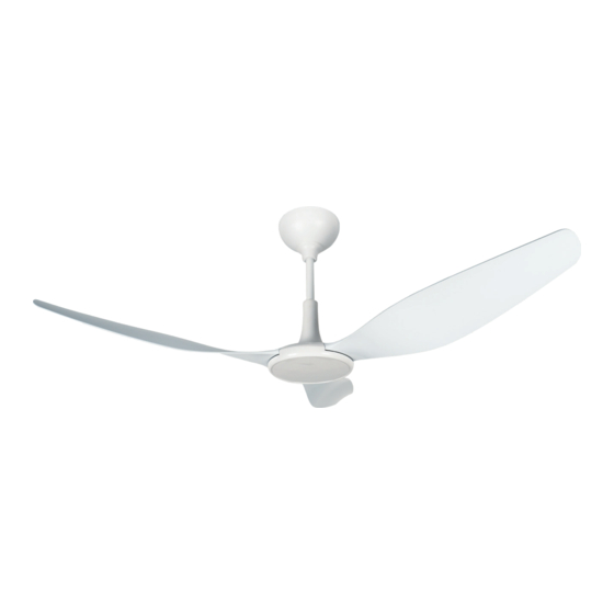
AMPLIFY™ Model DM, Size 5
NOTE: AMPLIFY™ model DM fan components can
weigh 20 lbs. or greater depending upon the fan size
and accessories that are provided. A suitable means for
lifting the weight of the fan to the mounting point, such
as a ladder or scissor lift, should be used for all DM fan
installations.
Document 486131
Overhead Ceiling Fans
Overhead Ceiling Fans
1
Advertisement
Table of Contents
Troubleshooting

Related Manuals for Greenheck AMPLIFY DM


Summary of Contents for Greenheck AMPLIFY DM
-
Page 1: Required Tools
Document 486131 AMPLIFY™ Model DM, Size 5 Overhead Ceiling Fans ® Installation, Operation and Maintenance Manual Please read and save these instructions for future reference. Read carefully before attempting to assemble, install, operate or maintain the product described. Protect yourself and others by observing all safety information. Failure to comply with these instructions will result in voiding of the product warranty and may result in personal injury and/or property damage. -
Page 2: Table Of Contents
Table of Contents General Information Operation And Maintenance Required Tools ..... 1 Pre-Start-Up Checks....12 General Safety Information . - Page 3 WARNING WARNING To reduce the risk of fire, electric shock, or injury to To reduce the risk of fire, electric shock, or personal persons, observe the following: injury, mount directly to a structural framing member 1. Use this unit only in the manner intended by the or to an outlet box marked “Acceptable for fan manufacturer.
-
Page 4: Receiving
Storage ATTENTION Fans are protected against damage during shipment. If Lors de toute intervention sur la soufflante, le moteur the unit cannot be installed and operated immediately, peut être suffisamment chaud pour provoquer une precautions need to be taken to prevent deterioration of douleur voire une blessure. -
Page 5: Fan Components
Fan Components NOTE: Hardware quantities listed below indicate what is required to complete installation. Hardware kits may Verify that all of the following parts and hardware include extra fasteners as a convenience. have been received prior to beginning installation. Contact your local representative or the manufacturer if replacement parts are required. -
Page 6: Pre-Installation
Pre-Installation Pre-Installation Checks 7. If the building has a mezzanine or other elevated spaces that may be occupied by people, verify that IMPORTANT: Consult all applicable national, state no component of the fan can be reached from the and local codes to ensure that all necessary code highest level or deck. -
Page 7: Minimum Spacing Requirements
Minimum Spacing Requirements 3 FT. CLEARANCE AROUND BLADES 3 FT. CLEARANCE AROUND BLADES HVAC DIFFUSER 2X FAN DIAMETER FROM HVAC WHEN FULL DIFFUSER OUTLET IS BELOW FAN, FAN MUST BE 1X FAN DIAMETER AWAY Minimum Spacing From Center of Fan (ft.) Fan Size (ft.) Fan Diameter (in.) Mechanical Installation... -
Page 8: Motor/Hub To Downtube Installation
2. Route supply power wiring (by others) to the fan’s 4. Reinstall the M6 x 35 mm bolts that were mounting location. Secure wiring to the building previously set aside to secure the motor/hub structure, making sure to follow all local and assembly to the downtube. -
Page 9: Safety Retention Cable Installation
8. Remove the pre-installed M5 x 20 mm bolts and 13. Slide the motor driver bracket into the universal fixed plate from the universal mounting bracket mounting yoke. Re-install the M5 x 12 mm screws and set aside. that were previously set aside to secure the motor driver bracket to the universal mounting yoke. -
Page 10: Airfoil Blade Installation
Airfoil Blade Installation Required Loose Components (Included): • Airfoil Blade (3) IMPORTANT: Do not operate fans without the airfoil blades. Failure to comply with this warning will result • M6 x 20 mm Airfoil Screws (6) in voiding of the product warranty and may result in Hardware/Tools Needed: permanent damage to the motor. -
Page 11: Electrical Installation
Electrical Installation Power Wiring 2. Secure any loose power cable to the building structure to ensure it does not interfere with fan DANGER performance. Always disconnect, lock and tag power source before 3. Remove the pre-installed M3 x 12 mm bolts from installing or servicing. -
Page 12: Operation And Maintenance Pre-Start-Up Checks
Operation And Maintenance Pre-Start-Up Checks RF Remote Control Pairing (Single Fan) 1. Disconnect and lock-out all power switches to fan. NOTE: Each fan includes an RF remote control that is paired with its motor driver at the factory prior to 2. -
Page 13: Fan Operation
Fan Operation Fan Maintenance IMPORTANT: If unusual vibration or oscillating NOTE: Installation and maintenance are to be movement is observed during fan operation, performed only by qualified personnel who are familiar immediately discontinue use of the fan and contact the with local codes and regulations and have experience manufacturer or a suitably qualified maintenance/repair with this type of equipment. -
Page 14: Troubleshooting
Troubleshooting Each fan bears a manufacturer’s nameplate with the DANGER fan’s model number and a unique serial number for Disconnect and secure to the ‘OFF’ position all identification. This information will assist the local electrical power to the fan prior to inspection or representative and the manufacturer in providing service servicing. -
Page 15: Controls Troubleshooting
Controls Troubleshooting Problem: One or more fans not pairing with RF remote control. Is supply power turned on at all circuit breakers and fan No supply power to fans. Turn circuit breakers and disconnects? disconnects to “on” position. Is there line voltage across L1 and L2/N on supply power Supply power wiring not connected or fuses damaged/ wiring? - Page 16 Problem: One or more fans run intermittently, but will not run consistently. Are line voltage measurements within +/- 10% of nominal Phase imbalance or incorrect supply power applied to voltage across L1 and L2/N on supply power wiring? fan. Correct supply power wiring to fan. ...
-
Page 17: Reference
Reference Universal Mounting Yoke Dimensions 2.44 in. 4.20 in. 5.35 in. 6.30 in. 7.28 in. Exploded View Diagram UNIVERSAL MOUNTING YOKE UNIVERSAL MOUNTING BRACKET MOTOR DRIVER ASSEMBLY MOUNT COVER DOWNTUBE ASSEMBLY MOTOR/HUB ASSEMBLY AIRFOIL BLADES Overhead Ceiling Fans ®... -
Page 18: Maintenance Log
Maintenance Log Date ___________________Time _____________ AM/PM Date ___________________Time _____________ AM/PM Notes: ___________________________________________ Notes: ___________________________________________ _________________________________________________ _________________________________________________ _________________________________________________ _________________________________________________ _________________________________________________ _________________________________________________ _________________________________________________ _________________________________________________ Date ___________________Time _____________ AM/PM Date ___________________Time _____________ AM/PM Notes: ___________________________________________ Notes: ___________________________________________ _________________________________________________ _________________________________________________ _________________________________________________ _________________________________________________ _________________________________________________ _________________________________________________ _________________________________________________ _________________________________________________ Date ___________________Time _____________ AM/PM... - Page 19 Maintenance Log Date ___________________Time _____________ AM/PM Date ___________________Time _____________ AM/PM Notes: ___________________________________________ Notes: ___________________________________________ _________________________________________________ _________________________________________________ _________________________________________________ _________________________________________________ _________________________________________________ _________________________________________________ _________________________________________________ _________________________________________________ Date ___________________Time _____________ AM/PM Date ___________________Time _____________ AM/PM Notes: ___________________________________________ Notes: ___________________________________________ _________________________________________________ _________________________________________________ _________________________________________________ _________________________________________________ _________________________________________________ _________________________________________________ _________________________________________________ _________________________________________________ Date ___________________Time _____________ AM/PM...
- Page 20 As a result of our commitment to continuous improvement, Greenheck reserves the right to change specifications without notice. Product warranties can be found online at Greenheck.com, either on the specific product page or in the literature section of the website at Greenheck.com/Resources/Library/Literature.