Table of Contents
Advertisement
Quick Links
®
Installation, Operation and Maintenance Manual
Please read and save these instructions for future reference. Read carefully before attempting to assemble, install,
operate or maintain the product described. Protect yourself and others by observing all safety information. Failure
to comply with these instructions will result in voiding of the product warranty and may result in personal injury
and/or property damage.
IMPORTANT: DS fans must be installed with the supplied CAT-5e communication cable or shielded CAT-5e
(by others) that complies with the following specifications. Cable must be twisted pair, shielded 26 ga. CAT-5e
cable with a drain wire and must be compliant with ISO 11801. Cable must use shielded RJ45 connectors with
a soldered drain and wiring configuration must follow EIA/TIA T568B wiring pinout. Individual CAT-5e cable
lengths must not exceed 200 ft. in order to prevent network communication issues.
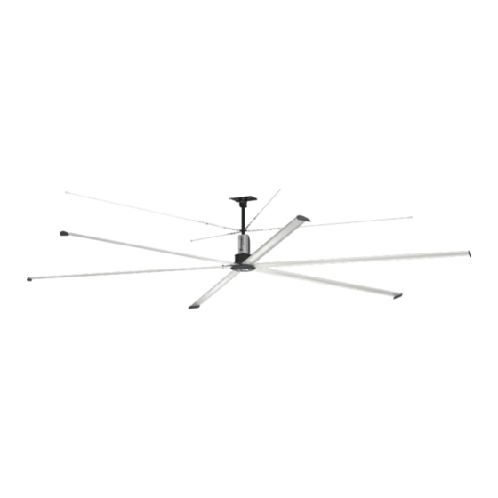
AMPLIFY™ Models DS-3 and DS-6 are the ideal choice for providing year-round comfort in air circulation and
destratification applications. Featuring an aerodynamic, extruded aluminum airfoil design and a high efficiency direct
drive motor, model DS delivers maximum airflow at a fraction of the operating cost of other HVLS fans. And, with its
universal ceiling mount, the DS fan is the easiest HVLS fan to install in the market!
Required Tools
The following tools will be required to complete the
installation of every DS fan. Additional tools may be
required depending on the application and installation
location of the fan.
• Socket Wrench with 7/16 in., 1/2 in., 9/16 in.,
3/4 in. and 17mm Sockets
• 7/16 in., 1/2 in., 9/16 in. and 3/4 in. Wrenches
• Adjustable Wrench
• Torque Wrench (up to 50 ft∙lbf)
• Torque Wrench (up to 120 in∙lbf)
• Drill and 9/16 in. Drill Bit
• Phillips Screwdriver
®
• Level
• Impact Driver
• #2 Phillips Bit and Driver
• 3/8 in. Magnetic Nut Driver
• Magnetic Nut Driver Extension
NOTE: AMPLIFY™ Model DS fan components can
weigh 90 lbs. or greater depending upon the fan size
and accessories that are provided. A suitable means
for lifting the weight of the fan to the mounting point,
such as a scissor lift, should be used for all DS fan
installations.
Document 483568
AMPLIFY™ Model DS
Overhead Ceiling Fans
Overhead Ceiling Fans
1
Advertisement
Table of Contents
Troubleshooting

Related Manuals for Greenheck AMPLIFY DS


Summary of Contents for Greenheck AMPLIFY DS
-
Page 1: Required Tools
Document 483568 AMPLIFY™ Model DS Overhead Ceiling Fans ® Installation, Operation and Maintenance Manual Please read and save these instructions for future reference. Read carefully before attempting to assemble, install, operate or maintain the product described. Protect yourself and others by observing all safety information. Failure to comply with these instructions will result in voiding of the product warranty and may result in personal injury and/or property damage. -
Page 2: Table Of Contents
Table of Contents Quick Start Guide Fan Networking Step 1 - Step 12 ....3-10 First Fan ..... . 36-37 All Remaining Fans. -
Page 3: Quick Start Guide
Quick Start Guide REFER TO INSTALLATION MANUAL FOR COMPLETE INSTALLATION INSTRUCTIONS. QUICK START GUIDE DOES NOT REPLACE INSTALLATION MANUAL INSTRUCTIONS. STEP #1 - MOUNT INSTALLATION 1/2 in. - 13 x 2.5 GRADE 8 BOLT STEEL I-BEAM INSTALLATION STEEL BEAM MANUAL PAGE 17 ... - Page 4 Z-PURLIN INSTALLATION IMPORTANT: TORQUE ALL BOLTS TO 80 FT-LBF (108.5 N-m) MANUAL PAGE 20 1/2 in. - 13 GRADE 8 NYLON LOCKNUT FASTENER KIT 915431 1/2 in. WASHER Z-PURLIN BRACKET IMPORTANT: Z-PURLINS MUST HAVE 1/2 in. - 13 x 1.75 GRADE 8 BOLT Z-PURLIN MINIMUM 2 IN.
- Page 5 STEP #2 - MOTOR INSTALLATION M4 - 0.7 x 10 MACHINE SCREW DOWNTUBE AND MOUNT ASSEMBLY MOTOR INSTALLATION MANUAL PAGES 22-23 HALL CONNECTION FASTENER KIT 915065 FRONT VFD COVER POWER GROUND IMPORTANT: ELECTRICAL CABLES FROM MOTOR MUST BE ON SAME 3/8 in.
- Page 6 STEP #4 - AIRFOIL INSTALLATION TORQUE TO 25 FT LBF (34 N m) AIRFOIL INSTALLATION MANUAL PAGES 26-27 FASTENER KIT 854832 (3 AIRFOILS) OR 915066 (6 AIRFOILS) TORQUE TO 60 IN LBF (6.8 N m) STEP #5 - HUB PLATE INSTALLATION HUB PLATE INSTALLATION ...
- Page 7 STEP #7 - MOTOR CABLE CONNECTION TO VFD MOTOR CABLE CONNECTION TO VFD MANUAL PAGES 30-32 IMPORTANT: PLUGS MUST BE FULLY SEATED AND IN PROPER ORIENTATION FOR FAN OPERATION HALL CABLE COLOR MOTOR POWER PINOUT REFERENCE HALL CONNECTION NOTE: HALL CABLE PLUG HAS BUILT-IN ALIGNMENT TAB DO NOT FORCE THIS PLUG MOTOR GROUND...
- Page 8 STEP #10 - FAN NETWORKING FIRST FAN IN SERIES ALL OTHER FANS IN SERIES FIRST FAN IN DAISY-CHAIN MANUAL PAGES 36-37 NO VFD WIRING MODIFICATIONS REQUIRED FIRE + FIRE + FIRE - FIRE - DATA + DATA + ...
- Page 9 STEP #11 - CONTROLS INSTALLATION SURFACE MOUNT KEYPAD CONTROL RECESSED MOUNT KEYPAD CONTROL REFER TO CONTROL MANUAL PAGE 2 REFER TO CONTROL MANUAL PAGES 2-3 KEYPAD CONTROL FACTORY-SUPPLIED SHIELDED CAT-5e CABLE TO FAN(S) FACTORY-SUPPLIED SHIELDED CAT-5e CABLE TO FAN(S) FACTORY-SUPPLIED SHIELDED 90°...
- Page 10 STEP #11 - CONTROLS INSTALLATION (CONTINUED) RECESSED MOUNT ADVANCED TOUCHSCREEN CONTROL REFER TO CONTROL MANUAL PAGES 3-4 FACTORY-INSTALLED RJ12 CABLE TO TOUCHSCREEN INTERFACE TOUCHSCREEN INTERFACE TRIM PLATE FACTORY-SUPPLIED SHIELDED RECESSED MOUNT ENCLOSURE CAT-5e CABLE TO FAN(S) FACTORY-INSTALLED RJ12 CABLE TO TOUCHSCREEN INTERFACE OPTIONAL BMS WIRING FACTORY-INTALLED 115V...
-
Page 11: General Information
General Information General Safety Information WARNING IMPORTANT: To reduce the risk of fire, electric shock, This appliance can be used by children aged from 8 or injury to persons, Model DS fans must be installed years and above and persons with reduced physical, with a mount assembly, motor assembly and airfoils that sensory or mental capabilities or lack of experience are marked (on their cartons) to indicate suitability with... -
Page 12: Receiving
Storage DANGER Fans are protected against damage during shipment. If Always disconnect, lock, and tag power source before the unit cannot be installed and operated immediately, installing or servicing. Failure to disconnect power precautions need to be taken to prevent deterioration of source can result in fire, shock or serious injury. -
Page 13: Fan Components
Fan Components NOTE: Hardware quantities listed below indicate what is required to complete installation. Hardware kits may Verify that all of the following parts and hardware include extra fasteners as a convenience. have been received prior to beginning installation. Contact your local representative or the manufacturer if replacement parts are required. - Page 14 Optional Fan Components Z-Purlin Mounting Kit (Optional) I-Beam Mounting Kit (Optional) I-Beam Clamping I-Beam Clamping Plate (2) Plate Shim (2) Z-Purlin Backing Z-Purlin Mounting Plate (2) Bracket (2) GRADE 8 HEX BOLT HEX BOLT Z-PURLIN 1/2 in. - 13 x 1-3/4 1/2 in.
-
Page 15: Pre-Installation
Pre-Installation Pre-Installation Checks 9. If the fan is to be mounted in an area where materials or equipment may be elevated into its IMPORTANT: Consult all applicable national, state path, ensure that the floor is marked or painted and local codes to ensure that all necessary code to alert personnel of the overhead location of the requirements are met. -
Page 16: Minimum Spacing Requirements
Minimum Spacing Requirements 3 FT. CLEARANCE AROUND BLADES 3 FT. CLEARANCE AROUND BLADES HVAC DIFFUSER 2X FAN DIAMETER FROM HVAC WHEN FULL DIFFUSER OUTLET IS BELOW HVLS FAN, HVLS FAN MUST BE 1X FAN DIAMETER AWAY MINIMUM 10 FT. ABOVE FINISHED FLOOR Minimum Spacing From Center of Fan (ft.) Fan Size (ft.) -
Page 17: Mechanical Installation
Mechanical Installation Mounting Installation Hardware/Tools Needed (Not Included): • Torque Wrench DANGER • 3/4 in. Socket and Ratchet Always disconnect, lock and tag power source before • 3/4 in. Wrench installing or servicing. Failure to disconnect power source can result in fire, shock or serious injury. 1. -
Page 18: Steel Truss Mounting
STRUCTURAL STEEL ANGLES Steel Truss Mounting Kit (BY OTHERS) STEEL TRUSS / BAR JOIST IMPORTANT: Structural Engineer of Record (SEOR) must perform thorough evaluation of mounting structure and determine final mounting requirements before fan is installed. Manufacturer is not liable for any problems TORQUE TO 80 FT LBF (108.5 N m) that arise as the result of insufficient structure, including... -
Page 19: Wood Beam Mounting
Wood Beam Mounting Kit 1/2 in. - 13 GRADE 8 NYLON LOCKNUT (For Beams 4-1/2 - 8-7/8 in. Wide) 1/2 in. WASHER IMPORTANT: Structural Engineer of Record (SEOR) WOOD BEAM BRACKET must perform thorough evaluation of mounting structure and determine final mounting requirements before fan is installed. -
Page 20: Z-Purlin Mounting
2. Mount z-purlin mounting brackets and backing Z-Purlin Mounting Kit plates using supplied (8) 1/2 in. – 13 x 1-3/4 in. IMPORTANT: Structural Engineer of Record (SEOR) grade 8 hex bolts, (16) 1/2 in. washers, and (8) 1/2 must perform thorough evaluation of mounting structure in. -
Page 21: Unistrut Mounting
Unistrut ® Mounting Kit (By Others) IMPORTANT: Structural Engineer of Record (SEOR) must perform thorough evaluation of mounting structure and determine final mounting requirements before fan is installed. Manufacturer is not liable for any problems UNISTRUT COMPONENTS that arise as the result of insufficient structure, including (BY OTHERS) (but not limited to) vibration, noise, or safety hazards. -
Page 22: Motor/Hub To Downtube Installation
Motor/Hub to Downtube Installation 3. If fan was supplied with the optional LED light assembly, connect the male light power (3 pin) and Required Loose Components (Included): light communication (2 pin) plugs in the • Motor/Hub Assembly (1) motor/hub assembly to their corresponding female connectors in the downtube. -
Page 23: Safety Retention Cable Installation
NOTE: The rear VFD cover should be installed with the of the safety retention cable and the saddle over the “G” on the Greenheck logo closest to the motor (not live-end of the safety cable. Failure to install steel critical for fan operation). -
Page 24: Gripple® Hardware (Optional)
® 5. Insert the loose end of the safety cable into the Gripple Hardware (Optional) open hole of the No. 4 Gripple connector. Note Components required from Bag # 915067: that the cable will only feed through the Gripple ® •... -
Page 25: Guy Wire Installation
Guy Wire Installation IMPORTANT: Steel cable clamps consist of two parts: the u-bolt and the saddle. Steel cable clamps must be IMPORTANT: Guy wires must be installed 45º to 60º installed with the u-bolt over the dead-end of the guy from vertical to ensure proper functioning. -
Page 26: Gripple® Hardware (Optional)
® 4. Place a level against the downtube and tighten all Gripple Hardware (Optional) (4) turnbuckles by hand in a crisscross pattern until IMPORTANT: Guy wires must be installed 45º to 60º the guy wires are tight and the fan is level. from vertical to ensure proper functioning. -
Page 27: Hub Plate Installation
Required Components from Bag # 915066 OR 854832: 4. Repeat steps 1 through 3 on remaining airfoil blades. Torque the installed bolts to 25 ft∙lbf • #10 – 12 x 3/4 in. Screw (6 OR 12) (34 N∙m). • 5/16 in. Washers (12 OR 24) •... -
Page 28: Led Light Installation (Optional)
LED Light Installation (Optional) 5. Raise the hub covering plate until the holes in the plate are aligned with the u-nuts on the hub IMPORTANT: Use only with light kits marked suitable retention bracket. Install (4) 1/4 in. – 20 x 3/4 in. for use in damp locations. -
Page 29: Fire System Integration
Fire System Integration Fire System Integration (Optional) IMPORTANT: The fire alarm relay should only be installed by qualified personnel who are familiar with The following instructions apply to fans that were the operation of building fire suppression systems. It is supplied with plug-and-play factory wiring. -
Page 30: Electrical Installation
Electrical Installation Motor Cable Connection IMPORTANT: The motor power, motor ground, and hall sensor cables are not long enough to reach the VFD 1. Using a phillips screwdriver, remove the black circuit board from the rear side. If the cables are not plastic cover on the front side of the VFD and set properly routed to the front of the VFD, the motor must aside. - Page 31 Motor Power and Ground Cable Connection Overhead Ceiling Fans ®...
- Page 32 Hall Sensor Cable Connection Overhead Ceiling Fans ®...
-
Page 33: Power Wiring
Power Wiring 4. Secure any loose power cable to the building structure to ensure it does not interfere with fan DANGER performance. Always disconnect, lock and tag power source before Without Optional Electrical Plug installing or servicing. Failure to disconnect power 1. -
Page 34: Led Light Wiring (Optional)
LED Light Wiring (Optional) Communication Wiring Power On/Off By Building Light Grid IMPORTANT: DS fans must be installed with the supplied CAT-5e communication cable or shielded Use the following instructions to wire fan-mounted LED CAT-5e (by others) that complies with the following lights for power on/off control via high-voltage from the specifications. -
Page 35: With Optional 1,000 Ft. Bulk Spool Of Cat-5E Cable
b. Plug an additional CAT-5e control cable into the 1 2 3 4 5 6 7 8 2-way RJ45 splitter located at the top of the 1. White/Orange downtube on the first fan. Connect the other 2. Orange 3. White/Green end of this CAT-5e cable into the 2-way splitter 4. -
Page 36: Fan Networking
Fan Networking If networking multiple fans to run using a single control Modbus Address Settings - Dipswitch 3 source, the dipswitch settings and wiring on each fan’s Modbus Position Position Position Position Position Position VFD circuit board will need to be adjusted using the Number Address 6, 7, 8... - Page 37 First Fan Overhead Ceiling Fans ®...
-
Page 38: All Remaining Fans
All Remaining Fans Modbus Address Settings - Dipswitch 3 1. Set dipswitch 2 as shown below. Dipswitch 2 is Modbus Position Position Position Position Position Position Number Address 6, 7, 8 used to set parameters that improve network function and will need to be adjusted for all fans in RESERVED FOR HVLS FAN CONTROLS the network except for the first fan. - Page 39 All Remaining Fans Overhead Ceiling Fans ®...
-
Page 40: Operation And Maintenance Pre-Start-Up Checks
Operation And Maintenance Pre-Start-Up Checks Fan Maintenance 1. Disconnect and lock-out all power switches to fan. NOTE: Installation and maintenance are to be performed only by qualified personnel who are familiar 2. Check all fasteners on the ceiling mount, mounting with local codes and regulations and have experience kit, blades, VFD, motor and accessories for with this type of equipment. -
Page 41: Troubleshooting
Troubleshooting Each fan bears a manufacturer’s nameplate with the DANGER fan’s model number and a unique serial number for Disconnect and secure to the ‘OFF’ position all identification. This information will assist the local electrical power to the fan prior to inspection or representative and the manufacturer in providing service servicing. -
Page 42: Controls Troubleshooting
Controls Troubleshooting Problem: Keypad or Standard Touchscreen control will not turn on. Is the 24V wire (white-brown) connected on VFD circuit No supply power to control. Controls are powered by board of fan 1 (directly connected to control via shielded VFD on fan 1 (directly connected to control via shielded ... - Page 43 Problem: One or more fans not found by control. Were fans and controls installed using only the provided Networking components may be defective, incorrectly networking components (green shielded CAT-5e cables, wired, or do not meet required specifications. Replace black shielded 3-way RJ45 splitters) or components that with provided components or components that comply comply with specifications on page 34?
-
Page 44: Fan Troubleshooting
Fan Troubleshooting Problem: One or more fans found by control but will not run. Have all fault codes been acknowledged and reset on fan One or more fans may have experienced a fault. Refer control? to list of fault codes on page 50 for detailed descriptions. ... - Page 45 Problem: One or more fans run intermittently, but will not run consistently. Have all fault codes been acknowledged and reset on fan One or more fans may have experienced a fault. Refer control? to list of fault codes on page 50 for detailed descriptions. ...
- Page 46 Problem: One or more fans run, but I don’t feel much airflow. Are fans installed with a minimum of 3 feet of clearance to Fan is starved for air. Correct installation to maintain ceiling structure? minimum clearance requirements. Are fan size and blade count set appropriately in the Incorrect torque/speed command to fans.
- Page 47 Problem: One or more fans not operating after fire suppression system testing. Has fire alarm been cleared and reset in the building? Fans are shutdown due to fire alarm. Clear fire alarm and reset fire suppression system. Fans will not operate during ...
-
Page 48: Led Light Troubleshooting
LED Light Troubleshooting Problem: LED Light will not turn on. Is supply power turned on at all circuit breakers and LED No supply power to LED light. LED light requires a light disconnects? separate 115V power source (light is not powered by ... - Page 49 Problem: LED light will not dim. Has an LED light been selected in the fan control for the Control is not sending commands to LED light. Refer to appropriate fan? the appropriate control manual for instructions on selecting LED light in the control.
-
Page 50: Reference
Reference Fault Code Causes and Possible Solutions Code Fault Description Possible Cause(s) Solution No Fault Fan is operating as expected Modbus Inconsistent Modbus 1. Loose CAT-5e cable connections 1. Verify that all CAT-5e cable connections Timeout RTU communication 2. Unshielded or damaged CAT-5e cables are fully seated and secure between control and and RJ45 splitters... -
Page 51: Modbus Register List
Modbus Registers List HVLS fan VFDs are configured for Modbus RTU communication as standard. The Modbus register list is for applications where a building management system (BMS) or field-supplied control are to be used for fan operation. A baud rate of 19200 bps and a device polling delay of 260 ms are recommended for network functionality. Register Name R/W Retentive Signed Format... -
Page 52: Installation Checklist
® HVLS Installation Checklist Project Name: _________________________________________________________________________________________ Name of Installer’s Company: ___________________________________________________________________________ Serial Number(s) of Fan(s): ______________________________________________________________________________ The following checklist provides an overview of typical installation and troubleshooting procedures but is not intended to replace the installation, operation, and maintenance (IOM) manuals provided with the fan and control. To ensure a positive outcome, please read and follow all provided instructions including those found in this checklist, the fan and controls IOMs, and any other written instructions provided by the manufacturer. - Page 53 Controls – Controls have been installed in a safe environment for the specific control model. Fire Alarm Relay – If the building is equipped with a fire suppression system, the Greenheck supplied fire alarm relays have been installed and tested by qualified personnel who are familiar with the operation of building fire suppression systems.
- Page 54 VFD circuit board for the first and second fans in the daisy-chain. Photos have been saved for future reference. Shielded CAT-5e Cable – I have taken a photo showing that fans were installed using only Greenheck- supplied CAT-5e cable or shielded CAT-5e cable that complies with the specifications included in the IOM.
-
Page 55: Maintenance Log
Maintenance Log Date ___________________Time _____________ AM/PM Date ___________________Time _____________ AM/PM Notes: ___________________________________________ Notes: ___________________________________________ _________________________________________________ _________________________________________________ _________________________________________________ _________________________________________________ _________________________________________________ _________________________________________________ _________________________________________________ _________________________________________________ Date ___________________Time _____________ AM/PM Date ___________________Time _____________ AM/PM Notes: ___________________________________________ Notes: ___________________________________________ _________________________________________________ _________________________________________________ _________________________________________________ _________________________________________________ _________________________________________________ _________________________________________________ _________________________________________________ _________________________________________________ Date ___________________Time _____________ AM/PM... - Page 56 As a result of our commitment to continuous improvement, Greenheck reserves the right to change specifications without notice. Product warranties can be found online at Greenheck.com, either on the specific product page or in the literature section of the website at Greenheck.com/Resources/Library/Literature.