Garmin GNS 530 Pilot's Manual & Reference
Hide thumbs
Also See for GNS 530:
- Pilot's manual and reference (282 pages) ,
- Pilot's manual & reference (198 pages) ,
- Installation manual (115 pages)
Table of Contents
Advertisement
Quick Links
Advertisement
Table of Contents
Troubleshooting

Related Manuals for Garmin GNS 530


Summary of Contents for Garmin GNS 530
- Page 1 GNS 530(A) Pilot’s Guide and Reference...
- Page 3 Revision Date of Revision 5/00 5/01 4/03 2/07 7/07 6/08 09/08 12/09 190-00181-00 Rev. H Description Initial Release Update to reflect software changes through 2.06 Update to reflect software changes through 4.0 Updated layout, added TAWS, TERRAIN, TIS, and Weather information, per SW v6.02 Updated per Main SW v6.03 Removed Proximity Advisory info from Section 14...
- Page 4 Garmin®, AutoLocate®, and PhaseTrac12® are registered trademarks of Garmin Ltd. or its subsidiaries and may not be used without the express permission of Garmin. GNS™ and Spell’N’Find™ are trademarks of Garmin Ltd. or its subsidiaries and may not be used without the express permission of Garmin.
-
Page 5: Table Of Contents
SECTION 1: INTRODUCTION ... 1-1 1.1 Accessories and Packing List ... 1-1 1.2 Key and Knob Functions ... 1-2 1.3 Takeoff Tour ... 1-5 SECTION 2: COM ... 2-1 2.1 Communicating using the GNS 530 ... 2-1 SECTION 3: NAV PAGES ... -
Page 6: Table Of Contents
TABLE OF CONTENTS SECTION 16: MESSAGES, ABBREVIATIONS, and NAV TERMS ... 16-1 16.1 Messages ... 16-1 16.2 Abbreviations ... 16-9 16.3 Navigation Terms ... 16-12 Appendix A: Data Card Use ...A-1 Appendix B: Specifications ...B-1 Appendix C: Troubleshooting Q & A ...C-1 GNS 530(A) Pilot’s Guide and Reference 190-00181-00 Rev. - Page 7 Terrain data is obtained from third party sources. Garmin is not able to independently verify the accuracy of the terrain data.
- Page 8 COATING. It is very important to clean the lens using a clean, lint-free cloth and an eyeglass lens cleaner that is specified as safe for anti-reflective coatings. CAUTION: The Garmin GNS 530 does not contain any user-serviceable parts. Repairs should only be made by an authorized Garmin service center. Unauthorized repairs or modifications could void both the warranty and the pilot’s authority to operate this device under FAA/FCC regulations.
- Page 9 Center; and 90 days for factory repaired or newly-overhauled products exchanged at Garmin in lieu of repair. Within the applicable period, Garmin will, at its sole option, repair or replace any components that fail in normal use. Such repairs or replacement will be made at no charge to the customer for parts or labor, provided that the customer shall be responsible for any transportation cost.
- Page 10 WARRANTY Blank Page viii GNS 530(A) Pilot’s Guide and Reference 190-00181-00 Rev. H...
-
Page 11: Section 1: Introduction
1.1 ACCESSORIES AND PACKING LIST Congratulations on choosing the finest, most advanced panel mount IFR navigation/communication system available. The GNS 530 represents Garmin’ s commitment to provide accurate, easy-to-use avionics. Before installing and getting started with the GNS 530, please check to see that the package includes the following items. -
Page 12: Key And Knob Functions
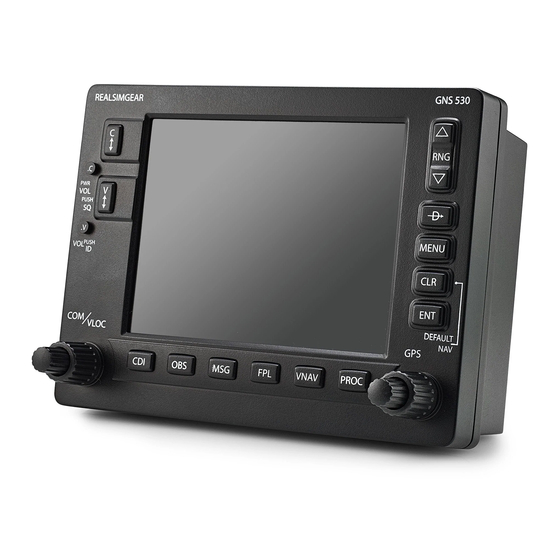
SECTION 1 INTRODUCTION 1.2 KEy AND KNOB FUNCTIONS The GNS 530 is designed to make operation as simple as possible. The key and knob descriptions (Figure 1-1) provide a general overview of the primary function(s) for each key and knob. The takeoff tour (Section 1.3) is intended to provide a brief overview of the primary functions of the GNS 530. - Page 13 Left-hand Keys and Knobs (1) COM Flip-flop Key – Swaps the active and standby COM frequencies. Press and hold to select emergency channel (121.500 MHz). (2) COM Power/Volume Knob – Controls unit power and communications radio volume. Press momentarily to disable automatic squelch control.
- Page 14 SECTION 1 INTRODUCTION NOTE: Data is entered using the large and small right knobs (Figure 1-2). Experiment with them to become efficient at entering data. This will greatly reduce the amount of time spent operating the GNS 530 in flight. Figure 1-2 Blank Direct-to Page NOTE: When the GNS 530 is displaying a list of information that is too long for the display...
-
Page 15: Takeoff Tour
Service staff is available during normal business hours (U.S. Central time zone) at the phone and fax numbers listed on page ii. Garmin can also be reached by mail (page ii) or at our website address, www.garmin.com. Powering up the GNS 530 The GNS 530’... - Page 16 SECTION 1 INTRODUCTION The Database Versions Page (Figure 1-5) appears next, which shows the current database information on the NavData and Terrain Data Cards. information highlighted in yellow indicates the database is not within its effective dates. The NavData database is updated every 28 days and must be current for approved instrument approach operations.
- Page 17 Figure 1-7 Fuel Flow Selected The Instrument Panel Self-test Page includes selections to set fuel on board to full capacity and access the Checklists Page. This allows the pilot to quickly set fuel to full limits and display any checklists that have been entered, such as start up or takeoff checklists.
-
Page 18: Exclusion
SECTION 1 INTRODUCTION Satellite Status Page The Satellite Status Page (Figure 1-10) appears as the GNS 530 attempts to collect satellite information. When an ‘Acquiring’ status is displayed on the Satellite Status Page, the signal strengths of any satellites received appear as ‘bar graph’... - Page 19 Selecting COM and VLOC Frequencies While the GNS 530 is acquiring a position, take a minute to dial in the active and standby frequencies to be used for the first phase of the flight. The GNS 530’ s display is divided into separate windows (or screen areas), including a COM Window, VLOC Window, and the GPS Window (Figure 1-12).
- Page 20 SECTION 1 INTRODUCTION Page Groups Page Groups NAV Group WPT Group AUX Group NRST Group see Section 3 see Section 7 see Section 10 see Section 8 Table 1-1 Page Groups The bottom right corner of the screen (Figure 1-14) indicates which page group (Table 1-1) is currently being displayed, the number of pages available within that group (indicated by square icons), and the placement of the...
- Page 21 Map Page After the GNS 530 acquires satellites and computes a position, the Map Page (Figure 1-15) appears automatically. Map Display Present Position Map Range Figure 1-15 Map Page The Map Page displays the present position (using an airplane symbol) relative to nearby airports, VORs, NDBs, intersections, user waypoints, and airspace boundaries.
- Page 22 SECTION 1 INTRODUCTION Repeat steps 2 and 3 to spell out the rest of the waypoint identifier (Figure 1-16). Figure 1-16 Direct-to Waypoint Page Press the ENT Key to confirm the identifier. The ‘Activate?’ function field is highlighted (Figure 1-17). Figure 1-17 ‘Activate?’...
- Page 23 Changing the data fields: From the Default NAV page, press the MENU Key and select ‘Change Fields?’ (Figure 1-19). Figure 1-19 Default NAV Page Menu Turn the large right knob to select the data field to be changed. Turn the small right knob to display a list of data options (Figure 1-20).
- Page 24 SECTION 1 INTRODUCTION A frequency listed on the NAV/COM Page can be quickly transferred to the standby field of the COM Window or the VLOC Window. This time-saving process prevents having to ‘re-key’ a frequency already displayed elsewhere on the screen. Selecting a communication or navigation frequency: Press the small right knob to activate the...
- Page 25 IFR Procedures Once the direct-to or flight plan is confirmed, the whole range of instrument procedures is available. Departures (SIDs), arrivals (STARs), non-precision and precision approaches are stored within the NavData card and are available using the PROC (procedures) Key. To display the Procedures Page (Figure 1-23), press the PROC Key.
- Page 26 SECTION 1 INTRODUCTION Nearest (NRST) Pages The NRST Page Group provides detailed information on the nine nearest airports, VORs, NDBs, intersections, and user-created waypoints within 200 nm of the current position. In addition, pages are also provided to display the five nearest center (ARTCC/FIR) and Flight Service Station (FSS) points of communication, plus alert the pilot to any nearby special-use or controlled airspaces.
- Page 27 Figure 1-26 Scrolling the Nearest Airport List Viewing additional information for a nearby airport: Press the small right knob to activate the cursor. Turn the large right knob to select the desired airport from the list. Press the ENT Key to display waypoint (WPT) information pages for the selected airport (Figure 1-27).
- Page 28 SECTION 1 INTRODUCTION Nearest (NRST) Airspace Page The last page in the NRST group, the Nearest Airspace Page (Figure 1-29), provides information for up to nine controlled or special-use airspaces near or in the flight path. Airspace information appears on this page based on the same criteria used for airspace alert messages: •...
- Page 29 Flight Plans (FPL) The GNS 530 lets the pilot create up to 20 flight plans with up to 31 waypoints in each flight plan. Flight plans are created, edited, and activated using the FPL Key. The FPL Page Group includes two pages: the Active Flight Plan Page and the Flight Plan Catalog Page (Figures 1-31 and 1-32).
- Page 30 SECTION 1 INTRODUCTION Repeat steps 5 and 6, above, until all waypoints for the flight plan have been entered (Figure 1-34). Figure 1-34 Enter Flight Plan Waypoints Once the flight plan is created, it may be activated from the Flight Plan Catalog Page Menu. Activating the flight plan places it into ‘flight plan 00’...
-
Page 31: Section 2: Com
SECTION 2: COM 2.1 COMMUNICATING USING THE GNS 530 The GNS 530 features a digitally-tuned VHF COM radio that provides a seamless transition from communication to navigation, bringing the two most important functions in flying together in one panel-mounted unit. The GNS 530’... - Page 32 SECTION 2 NOTE: The tuning cursor normally appears in the COM Window, unless placed in the VLOC Window by pressing the small left knob. When the tuning cursor is in the VLOC Window, it automatically returns to the COM Window after 30 seconds of inactivity.
- Page 33 Auto-Tuning The GNS 530’ s auto-tune feature allows the pilot to quickly select any database frequency in the GPS Window as the standby frequency. Any COM frequency displayed in the GPS Window can be transferred to the standby COM frequency field. The following are examples of selecting COM frequencies from some of the main GPS pages.
- Page 34 SECTION 2 Selecting a COM frequency for a nearby flight service station (FSS) or center (ARTCC): Turn the large right knob to select the NRST Page Group. Turn the small right knob to select the Nearest Center or Nearest Flight Service Page (Figure 2-7).
- Page 35 Selecting a COM frequency for any airport in the database: Turn the large right knob to select the WPT Page Group. Turn the small right knob to select the Airport Frequencies Page (Figure 2-9). Figure 2-9 Airport Frequencies Page Press the small right knob to place the cursor on the airport identifier field.
- Page 36 SECTION 2 Stuck Microphone As mentioned previously in this section, when the GNS 530 is transmitting, a ‘TX’ indication appears in the COM Window. If the microphone key is stuck or accidentally left in the on position; or the microphone continues to transmit after the key is released, the COM transmitter automatically times out (ceases transmitting) after 35 seconds of continuous broadcasting.
-
Page 37: Section 3: Nav Pages
SECTION 3: NAV PAGES 3.1 MAIN PAGE GROUPS The GNS 530’ s main pages are divided into four separate page groups: NAV, WPT, AUX, and NRST (Table 3-1). Each page group is comprised of multiple pages. The page groups are selected using the large right knob. -
Page 38: Nav Page Group
SECTION 3 NAV PAGES 3.2 NAV PAGE GROUP The NAV Page Group includes five pages (Figure 3-3). While viewing any NAV page, turn the small right knob to select a different NAV page. The pilot may find this selection process convenient to cycle between the Default NAV Page and the Map Page, which are two of the most frequently used pages. - Page 39 The graphic CDI shows the current position at the center of the indicator, relative to the desired course (the moving course deviation needle). As with a traditional mechanical CDI, when off course simply steer toward the needle. The TO/FROM arrow in the center of the scale indicates whether the aircraft is heading TO (up arrow) or FROM the waypoint (down arrow).
- Page 40 SECTION 3 NAV PAGES Selecting Desired On-Screen Data At the bottom of the Default NAV Page there are six user-definable fields which display the data needed as the flight progresses (Figure 3-3). By default these fields display: distance to destination (DIS), desired track (DTK), bearing to destination (BRG), ground speed (GS), ground track (TRK), and estimated time enroute (ETE).
- Page 41 A ‘Crossfill?’ option is also provided for the Default NAV Page. This option transfers a direct-to destination or flight plan to a second Garmin 400 or 500 Series unit. See Section 10.2, Flight Planning Page: Crossfill for additional details on using the crossfill option.
-
Page 42: Map Page
SECTION 3 NAV PAGES 3.4 MAP PAGE The second NAV page is the Map Page (Figure 3-9), which displays the present position using an airplane symbol, along with nearby airports, NAVAIDS, user- defined waypoints, airspace boundaries, lakes, rivers, highways, and cities. Map Display Present Position... - Page 43 An autozoom feature is available which automatically adjusts from an enroute range of 2000 nm through each lower range, stopping at a range of 1.0 nm when approaching the destination waypoint. The autozoom feature is turned on/off from the Map Setup Page (described in Section 3.4).
- Page 44 SECTION 3 NAV PAGES Map Panning Another Map Page function is panning, which allows the map to move beyond its current limits without adjusting the map range. When the panning function is selected (by pressing the small right knob), a target pointer flashes on the Map Display (Figure 3-12).
- Page 45 Map Direct-to Designating an on-screen airport, NAVAID, or user waypoint as the direct-to destination: Use the panning function (‘Map Panning’ in this section) to place the target pointer on a waypoint. Press the Direct-to Key to display the select Direct-to Waypoint Page, with the selected waypoint already listed (Figure 3-14).
- Page 46 SECTION 3 NAV PAGES ‘Review Airspace?’ should already be highlighted, if not select it with the small right knob. Press the ENT Key to display the Airspace Information Page for the selected airspace. To display the COM frequency(ies) for the controlling agency, turn the large right knob to highlight ‘Frequencies?’...
- Page 47 Changing the map orientation: From the Map Page Menu, turn the large right knob to highlight ‘Setup Map?’ (Figure 3-16) and press the ENT Key. Turn the small right knob to select ‘Map’ (Figure 3-18) and press the ENT Key. Figure 3-18 Map Setup Window Turn the large right knob to highlight the ‘Orientation’...
- Page 48 SECTION 3 NAV PAGES Enabling/disabling the wind vector, all background land data, or all Jeppesen aviation data: From the Map Page Menu, turn the large right knob to highlight ‘Setup Map?’ and press the ENT Key. Turn the small right knob to select ‘Map’ and press the ENT Key.
- Page 49 Distance Measurements The ‘Measure Dist?’ option provides a quick, easy method for determining the bearing and distance between any two points on the Map Display. Measuring bearing and distance between two points: From the Map Page Menu, turn the large right knob to highlight ‘Measure Dist?’...
-
Page 50: Restoring The Factory Default Settings
SECTION 3 NAV PAGES Clearing On-Screen Weather Data ‘Clear Storm Data?’ removes storm history information from the map. New storm data appears as detected and relayed by a connected weather data source. Weather data and the ‘Clear Storm Data?’ option are only available when the GNS 530 installation includes connection to weather information sources. -
Page 51: Terrain Page
3.5 TERRAIN PAGE NOTE: GNS 530 units may* display either a TERRAIN Page or a TAWS Page, (but not both) depending upon the installed hardware and configuration. * Some earlier units are not equipped to support the TERRAIN and/or TAWS functionality, so therefore will not have a TERRAIN or TAWS page available. - Page 52 SECTION 3 NAV PAGES Displaying a 120˚ view: Select the TERRAIN Page and press the MENU Key. Select ‘View 120˚?’ (Figure 3-28). Figure 3-28 TERRAIN Page Menu Press the ENT Key. To switch back to a 360˚ view, repeat step 1, select ‘View 360˚?, and press the ENT Key.
-
Page 53: Inhibit Mode
Inhibit Mode TERRAIN has an inhibit mode that deactivates the FLTA/ PDA aural and visual alerts. Pilots should use discretion when inhibiting TERRAIN and always remember to enable the system when appropriate. For more information, see Section 12.3, TERRAIN alerts. Inhibiting TERRAIN: Select the TERRAIN Page and press the MENU Key. -
Page 54: Taws Page
SECTION 3 NAV PAGES 3.6 TAWS PAGE NOTE: GNS 530 units may* display either a TERRAIN Page or a TAWS Page, (but not both) depending upon the installed hardware and configuration. * Some earlier units are not equipped to support the TERRAIN and/or TAWS functionality, so therefore will not have a TERRAIN or TAWS page available. - Page 55 Seven display ranges are available, allowing for a more complete view of the surrounding area. Changing the display range: Select the TAWS Page and press up or down on the RNG Key to select the desired range: 1 nm, 2 nm, 5 nm, 10 nm, 25 nm, 50 nm, 100 nm (Figure 3-36).
- Page 56 SECTION 3 NAV PAGES TAWS Manual Test Garmin TAWS provides a manual test capability which verifies the proper operation of the aural and visual annunciations of the system prior to a flight. Manually testing the TAWS system: Select the TAWS Page and press the MENU Key.
-
Page 57: Nav/Com Page
3.7 NAV/COM PAGE The NAV/COM (navigation communications) Page (Figure 3-35) provides a list of the airport communication and navigation frequencies at the departure, enroute, and arrival airports. The NAV/COM Page makes selection of the frequencies needed along the flight plan quick and convenient. - Page 58 SECTION 3 NAV PAGES Scrolling through the list of frequencies: Activate the cursor, if not already active, by pressing the small right knob. Turn the large right knob to move the cursor through the list of frequencies. If there are more frequencies in the list that can be displayed on the screen, a scroll bar along the right-hand side of the screen (Figure 3-44)
-
Page 59: Satellite Status Page
3.8 SATELLITE STATUS PAGE The Satellite Status Page provides a visual reference of GPS receiver functions, including current satellite coverage, GPS receiver status, and position accuracy. The Satellite Status Page (Figure 3-47) is helpful in troubleshooting weak (or missing) signal levels due to poor satellite coverage or installation problems. - Page 60 SECTION 3 NAV PAGES The Satellite Status Page also indicates the accuracy of the position fix, using Estimated Position Error (EPE), Dilution of Precision (DOP), and Horizontal Uncertainty Level (HUL) figures. DOP measures satellite geometry quality (i.e., number of satellites received and where they are relative to each other) on a scale from one to ten. The lowest numbers are the best accuracy and the highest numbers are the worst.
-
Page 61: Section 4: Direct-To Navigation
SECTION 4: DIRECT-TO NAVIGATION 4.1 OVERVIEW The GNS 530’ s direct-to function provides a quick method of setting a course to a destination waypoint. Once a direct-to is activated, the GNS 530 establishes a point-to-point course line (great circle) from the present position to the selected direct-to destination. - Page 62 SECTION 4 DIRECT-TO NAVIGATION Selecting a Destination by Facility Name or City In addition to selecting a destination by identifier, the Select Direct-to Waypoint Page (Figure 4-4) also allows the pilot to select airports, VORs and NDBs by facility name or city location.
- Page 63 Selecting a Destination from the Active Flight Plan When navigating an active flight plan, any waypoint contained in the flight plan may be selected as a direct-to destination from the Select Direct-to Waypoint Page. See Section 5, for more information on flight plans. Selecting a direct-to destination from the active flight plan: Press the Direct-to Key.
- Page 64 SECTION 4 DIRECT-TO NAVIGATION Selecting the Nearest Airport as a Direct-to Destination The Select Direct-to Waypoint Page always displays the nearest airports (from the present position) in the NRST field. Navigating directly to a nearby airport is always just a few simple steps away. (Nearby airports may also be selected as direct-to destinations using the steps described in Section 8.1.) Selecting a nearby airport as a direct-to...
- Page 65 If a list of waypoints is displayed on-screen: a) Press the small right knob to activate the cursor. b) Turn the large right knob to highlight the desired waypoint (Figure 4-11). Figure 4-11 Nearest List c) Press the Direct-to Key followed by the ENT Key twice.
- Page 66 SECTION 4 DIRECT-TO NAVIGATION Cancelling Direct-to Navigation Once a direct-to is activated, the GNS 530 provides navigation guidance to the selected destination until the direct-to is replaced with a new direct-to or flight plan, cancelled, or the unit is turned off. Cancelling a direct-to: Press the Direct-to Key to display the Select Direct-to Waypoint Page.
-
Page 67: Section 5: Flight Plans
SECTION 5: FLIGHT PLANS The GNS 530 lets the pilot create up to 20 different flight plans, with up to 31 waypoints in each flight plan. The Flight Plan Page Group consists of two pages (Active Flight Plan Page and Flight Plan Catalog Page; Figures 5-1 and 5-2), accessed by pressing the FPL Key. - Page 68 SECTION 5 FLIGHT PLANS A blank Flight Plan Page appears for the first empty storage location. Use the small and large right knobs to enter the identifier of the departure waypoint and press the ENT Key. Repeat step 4 to enter the identifier for each additional flight plan waypoint (Figure 5-4).
- Page 69 Deleting a waypoint from an existing flight plan: Press the FPL Key and turn the small right knob to display the Flight Plan Catalog Page. Press the small right knob to activate the cursor. Turn the large right knob to highlight the desired flight plan and press the ENT Key.
- Page 70 SECTION 5 FLIGHT PLANS Activating Flight Plans Once a flight plan is defined through the Flight Plan Catalog Page (using the steps outlined previously in this section), it may be activated for navigation. Activating the flight plan places it into ‘flight plan 00’ and overwrites any previous information at that location.
- Page 71 Copying Flight Plans To save a flight plan currently located in ‘flight plan 00’, copy it to an open catalog location (1-19) before the flight plan is cancelled, overwritten, or erased. Copying a flight plan to another flight plan catalog location: From the Active Flight Plan Page, press the MENU Key to display the Active Flight Plan Page Menu.
- Page 72 400-Series or 500-Series Garmin unit. Some crossfill operations can be done automatically. If both units are set to ‘auto’, a change in the direct-to destination or active flight plan on one unit is seen on the other.
-
Page 73: Deleting All Flight Plans
• ‘Copy Flight Plan?’ - Allows the pilot to copy the selected flight plan to a new flight plan location, as described previously in this section. The copy function is useful for duplicating an existing flight plan before making changes. •... -
Page 74: Active Flight Plan Page
SECTION 5 FLIGHT PLANS 5.2 ACTIVE FLIGHT PLAN PAGE The Active Flight Plan Page provides information and editing functions for ‘flight plan 00’, the flight plan currently in use for navigation. When a direct-to or flight plan has been activated, the Active Flight Plan Page shows each waypoint for the flight plan (or a single waypoint for a direct-to, Figure 5-18), along with the desired track (DTK) and distance (DIS) for each leg. - Page 75 Activate Leg which is currently used for navigation guidance). Allows the pilot to transfer the active flight plan between two 400- or 500-series Garmin units Crossfill in a dual unit installation. See Section 10.2, Flight Planning: Crossfill for additional information on this feature.
- Page 76 SECTION 5 FLIGHT PLANS The data fields for DTK and DIS are user-selectable and may be changed to display cumulative distance (CUM) to each waypoint, estimated time of arrival (ETA), estimated time enroute (ETE), or enroute safe altitude (ESA). Changing a data field on the Active Flight Plan Page: With the Active Flight Plan Page displayed, press the MENU Key to display the Active Flight...
- Page 77 Selecting an approach for a direct-to or flight plan destination airport: Choose the ‘Select Approach?’ option from the Active Flight Plan Page Menu (Figure 5-23) and press the ENT Key. Figure 5-23 Active Flight Plan Page Menu A window appears listing the available approaches (Figure 5-24) for the destination airport.
- Page 78 SECTION 5 FLIGHT PLANS Selecting an arrival for a direct-to or flight plan destination airport: Select the ‘Select Arrival?’ option from the Active Flight Plan Page Menu (Figure 5-26) and press the ENT Key. Figure 5-26 Active Flight Plan Page Menu A window appears listing the available arrivals (Figure 5-27) for the destination airport.
- Page 79 Removing an approach, arrival, or departure from the active flight plan: Select the ‘Remove Approach?’, ‘Remove Arrival?’, or ‘Remove Departure?’ option from the Active Flight Plan Page Menu (Figure 5-29) and press the ENT Key. Figure 5-29 Active Flight Plan Page Menu A confirmation window appears listing the procedure to be removed.
- Page 80 SECTION 5 FLIGHT PLANS Shortcuts A number of shortcuts are available to save time when using the Active Flight Plan Page. These shortcuts speed the process of removing approaches, departures and arrivals, and aid in selecting a specific flight plan leg for navigation guidance.
- Page 81 The ‘Activate Leg?’ option is discussed previously in this section, which allows the pilot to specify which leg of the flight plan is used for navigation guidance. A shortcut also exists for this operation, using the Direct-to Key. Activating a specific leg of the active flight plan: Press the small right knob to activate the cursor and turn the large right knob to...
- Page 82 SECTION 5 FLIGHT PLANS Blank Page 5-16 GNS 530(A) Pilot’s Guide and Reference 190-00181-00 Rev. H...
-
Page 83: Section 6: Procedures
SECTION 6: PROCEDURES 6.1 APPROACHES, DEPARTURES, AND ARRIVALS The GNS 530 allows the pilot to fly non-precision and precision approaches to airports with published instrument approach procedures. All available approaches are stored on the Jeppesen NavData card, and are automatically updated when the new card is inserted into the GNS 530. - Page 84 SECTION 6 PROCEDURES Turn the large right knob to highlight ‘Load?’ or ‘Activate?’ (approaches only) and press the ENT Key. (‘Load?’ adds the procedure to the flight plan without immediately using it for navigation guidance. This allows the pilot to continue navigating the original flight plan, but keeps the procedure available on the Active Flight Plan Page for quick activation when...
- Page 85 Another Procedures Page option allows the pilot to activate the final course segment of the approach. This option assumes the pilot will receive vectors to the final approach fix (FAF) and provides guidance to intercept the final course, before reaching the FAF. Activating the approach, with vectors to final: Press the PROC Key to display the Procedures...
- Page 86 SECTION 6 PROCEDURES Select Destination ‘Select’ and ‘Load’ the approach ‘Activate’ the approach DO NOT USE FOR NAVIGATION Figure 6-7 Sample Approach Approach operations on the GNS 530 typically begin with the same basic steps (refer to Figure 6-7 for the following steps): Select the destination airport using the Direct- to Key, or as the last waypoint in the active...
- Page 87 The steps required to set up and fly the approach are detailed below (refer to Figure 6-8 for the following steps): Prior to departing KFDK, the destination (KLYH) is selected using the Direct-to Key or by creating a flight plan terminating at Lynchburg Regional.
- Page 88 SECTION 6 PROCEDURES Flying the Procedure Turn DO NOT USE FOR NAVIGATION Figure 6-12 Sample Approach with Procedure Turn Refer to Figure 6-12 for the following steps: Within 30 nm of the destination airport, the GNS 530 switches from ‘enroute’...
- Page 89 Fly the outbound course. Approximately one minute after passing the FAF (LYH), the alert message ‘START PROC TRN’ appears along the bottom of the screen (Figure 6-16). Initiate the procedure turn at any time after receiving this alert message. Figure 6-16 Waypoint Alert DO NOT USE FOR NAVIGATION ...
- Page 90 SECTION 6 PROCEDURES 10) When approaching the FAF, a waypoint alert (‘NEXT DTK 026°’) appears in the lower right corner. Make any course adjustments necessary for the final course segment (FAF to MAP). 11) After crossing the FAF, the destination sequences to the MAP (‘RW04’, the runway threshold, see Figure 6-20).
- Page 91 The OBS Key is used to initiate the missed approach, as follows (refer to Figure 6-22 for the following steps): Press the OBS Key. The missed approach holding point (MAHP; in this case ‘SWARM’ intersection) is automatically offered as the destination waypoint.
- Page 92 SECTION 6 PROCEDURES Flying an Approach with a Hold Starting where the previous example left off, assume weather conditions resulted in a missed approach at Lynchburg Regional. The pilot has decided to divert to Farmville Regional (KFVX) instead (refer to Figure 6-24 for the following steps).
- Page 93 Figure 6-27 Terminal Mode Refer to Figure 6-27 for the following steps. As in the last example, within 30 nm of the airport, the GNS 530 switches from enroute to terminal mode, and the CDI scale transitions from 5.0 to 1.0 nm, full scale deflection.
- Page 94 SECTION 6 PROCEDURES DO NOT USE FOR NAVIGATION Figure 6-29 Approach Mode Refer to Figure 6-29 for the following steps. 11) When approaching BODRY intersection, a waypoint alert (’NEXT DTK 209°’) appears along the bottom of the screen. 12) At 2.0 nm from the FAF (DEPOY intersection), the GNS 530 switches from terminal mode to approach mode.
- Page 95 Figure 6-31 Final Approach 16) After crossing the MAP, ‘SUSP’ appears above the OBS Key, indicating that auto- matic sequencing of approach waypoints is suspended at the MAP. A ‘from’ indication is displayed on the CDI and Default NAV Page, but course guidance along the final approach course continues.
- Page 96 SECTION 6 PROCEDURES Figure 6-32 Enroute Mode This example is based upon a flight from Hutchinson (Kansas) Municipal (KHUT) to Billard Municipal (KTOP) in Topeka, Kansas. The VOR/DME runway 22 approach is selected, along with ‘D258G’ as the IAF (refer to Figure 6-32 for the following steps).
- Page 97 Refer to Figure 6-35 for the following steps. Within 30 nm of KTOP, the GNS 530 switches from enroute mode to terminal mode and the CDI scale transitions from 5.0 to 1.0 nm, full scale deflection. If the approach has not yet been activated (in step 2 above), do so when cleared for the approach (Figure 6-36).
- Page 98 SECTION 6 PROCEDURES Refer to Figure 6-38 for the following steps. DO NOT USE FOR NAVIGATION Figure 6-38 Approach Mode When approaching the FAF, ‘NEXT DTK 214°’ appears along the bottom of the screen (Figure 6-39). Select this course on the CDI (or HSI) using the OBS knob.
- Page 99 Vectors to Final Take a second look at the ‘VOR 22’ approach into Billard Municipal. Instead of following the DME arc, ATC tells the pilot to expect vectors onto the final approach course. There are several ways to select ‘vectors to final’ with the GNS 530.
- Page 100 SECTION 6 PROCEDURES From the Transitions Window, select ‘D258G’ as the IAF. Also, select ‘Load?’. When cleared, press the PROC Key and select ‘Activate Vector-To-Final?’ (Figure 6-42). Figure 6-42 Procedures Page Flying the Vectors Approach With ‘vectors to final’ selected, the CDI needle remains off center until the aircraft is established on the final approach course.
- Page 101 Figure 6-44 Procedures Page ATC instructs the pilot to turn left to a heading of 025°. This places the aircraft parallel to the final approach course in the opposite direction. CDI needle deflection is to the left. ATC instructs the pilot to turn right to a heading of 115°.
- Page 102 SECTION 6 PROCEDURES When crossing the FAF, the destination sequences to the MAP (‘RW22’). When approaching the MAP, a waypoint alert (‘APPRCHING WPT’) appears in the lower right corner. 10) After crossing the MAP, ‘SUSP’ appears above the OBS Key (Figure 6-48), indicating that automatic sequencing of approach waypoints is suspended at the MAP.
- Page 103 Figure 6-50 Waypoint Alert, Default NAV Page Fly the ‘course from fix to distance’ leg, as shown on the Active Flight Plan Page and the Default NAV Page. Note the magenta line in Figure 6-51, which represents the currently active leg of the approach. The distance (DIS) displayed on the above screens is TO the ‘D13.0’...
- Page 104 SECTION 6 PROCEDURES Course from fix to altitude legs show the specific target altitude on the Active Flight Plan Page and the Default NAV Page. The missed approach sequence for the Palmdale VOR/DME RWY 25 approach includes a course from fix to altitude leg. MISSED APPROACH: ...
- Page 105 An alert (‘NEXT DTK 119°’) appears, providing guidance to the inbound course (Figure 6-55) The actual desired track (DTK) depends on ground speed and distance from PMD VOR. Intercept and fly the inbound course. Figure 6-55 Waypoint Alert When approaching PMD VOR (the missed approach holding point), an alert message in the lower right-hand corner (Figure 6-56) of the screen recommends the holding pattern...
- Page 106 SECTION 6 PROCEDURES Course from fix to manual sequence legs appear on the Active Flight Plan Page and the Map Page with ‘man seq’ in place of a waypoint identifier. An example of this type of course leg appears in the COASTAL ONE DEPARTURE from Westfield, Massachusetts (Barnes Muni).
-
Page 107: Ils Approaches
Figure 6-59 Waypoint Alert When the OBS Key is pressed, the GNS 530 automatically sequences to each waypoint along the remainder of the departure route, including the selected transition. 190-00181-00 Rev. H 6.3 ILS APPROACHES Precision approaches can be performed with the GNS 530’... - Page 108 SECTION 6 PROCEDURES NOTE: When intercepting the approach course at a distance less than 2.0 nm from the FAF, the GNS 530 does not automatically switch the CDI to VLOC. In this case, press the CDI Key to manually switch from GPS to VLOC. Figure 6-61 ILS Approach 6-26 Selecting an ILS Approach...
- Page 109 Select Flagstaff Pulliam (KFLG) as the destination, using the Direct-to Key or as the last waypoint in a flight plan. Press the PROC (Figure 6-63) Key and select the ‘ILS 21’ approach using the steps outlined in Section 6.1. Figure 6-63 Procedures Page 190-00181-00 Rev.
- Page 110 SECTION 6 PROCEDURES Flying the ILS Approach When ‘Activate?’ is selected for an ILS approach, automatic switching of the external CDI is enabled (unless turned off from the CDI/Alarms Page). Once established on the inbound course to the FAF, the external CDI guidance automatically switches from ‘GPS’...
- Page 111 Figure 6-67 Alert Message DO NOT USE FOR NAVIGATION Figure 6-68 ILS Approach Course 190-00181-00 Rev. H Refer to Figure 6-68 for the following steps. Initiate the procedure turn. The GNS 530 does not provide guidance through the turn. (The procedure turn is displayed on the Map Page and indicated as the active leg on the Default NAV Page and the Active Flight Plan Page.)
- Page 112 SECTION 6 PROCEDURES 11) When approaching the FAF (SHUTR), ‘0.30nm’ appears in the lower left corner of the screen (Figure 6-70) indicating a CDI scale transition from 1.0 to 0.3 nm, full scale deflection. (This scale transition applies only to the Default NAV Page’s on-screen CDI, since the external CDI or HSI is now coupled to the VLOC receiver.
- Page 113 14) When approaching the MAP, a waypoint alert (‘APPRCHING WPT’) appears in the lower right corner (Figure 6-72). Figure 6-72 Waypoint Alert 15) After crossing the MAP, ‘SUSP’ appears above the OBS Key (Figure 6-73), indicating that automatic sequencing of approach waypoints is suspended at the MAP.
-
Page 114: Points To Remember For All Approaches
SECTION 6 PROCEDURES 6.4 POINTS TO REMEMBER FOR ALL APPROACHES • The GNS 530 is designed to complement printed approach plates and vastly improve situational awareness throughout the approach. However, the pilot must always fly an approach as it appears on the approach plate. - Page 115 • When an ILS approach is first selected and ‘loaded’ (or ‘activated’), the ILS frequency is automatically placed in the standby field. In order to fly the final course segment of the ILS approach, the pilot must place the ILS frequency in the active frequency field by pressing the VLOC Flip-flop Key.
- Page 116 SECTION 6 PROCEDURES Blank Page 6-34 GNS 530(A) Pilot’s Guide and Reference 190-00181-00 Rev. H...
-
Page 117: Section 7: Wpt Pages
SECTION 7: WPT PAGES 7.1 WPT PAGE GROUP Section 3.1 introduced the GNS 530’ s main page groups (Table 7-1)—NAV, WPT, AUX, NRST—and described each page in the NAV group. This second page group (WPT) provides information for the thousands of airports, VORs, NDBs, intersections, runways, frequencies, and procedures stored on the Jeppesen NavData card. - Page 118 SECTION 7 WPT PAGES Entering a waypoint identifier: Select the desired WPT page and press the small right knob to activate the cursor. Turn the small right knob to select the first character of the waypoint’s identifier. Turn the large right knob to select the next character field.
- Page 119 Duplicate Waypoints Once the identifier, facility name, or location is entered, all six airport pages display information for the selected airport. When entering an identifier, facility name, or location, the GNS 530’ s Spell’N’Find feature scrolls through the database, displaying those waypoints matching the characters that have been entered to that point.
-
Page 120: Airport Location Page
SECTION 7 WPT PAGES Selecting a waypoint identifier from a list of duplicates: Select the desired airport or NAVAID identifier following the preceding steps under ‘To enter a waypoint facility name or city location’. A Duplicate Waypoints Window appears (Figure 7-6). - Page 121 The following descriptions and abbreviations are used: • Type - Usage type: Public, Heliport, Military, or Private • Position - Latitude/Longitude (degrees/minutes or degrees/minutes/seconds), MGRS, or UTM/UPS • Elevation - In feet or meters • Fuel - For public-use airports, the available fuel type(s) are: Avgas (80-87/100LL/100-130/Mogas), Jet, or None •...
-
Page 122: Airport Runway Page
SECTION 7 WPT PAGES 7.3 AIRPORT RUNWAy PAGE The Airport Runway Page (Figure 7-9) displays runway designations, length, surface type, and lighting for the selected airport. A map image of the runway layout and surrounding area is also displayed on the Airport Runway Page. - Page 123 Adjusting the range of the map image: Press the down arrow of the RNG Key to display a smaller map area. Press the up arrow of the RNG Key to display a larger map area. The following descriptions and abbreviations are used on the Airport Runway Page: •...
-
Page 124: Airport Frequency Page
SECTION 7 WPT PAGES 7.4 AIRPORT FREQUENCy PAGE The Airport Frequency Page displays radio frequencies and frequency types for the selected airport, as well as sector and altitude restrictions (where applicable). If the selected airport has a localizer-based approach, the localizer frequency(ies) is also listed on the Airport Frequency Page (Figure 7-13). - Page 125 If a listed frequency has sector or altitude restrictions, the frequency is preceded by an ‘Info?’ designation (Figure 7-13). Viewing usage restrictions for a frequency: Turn the large right knob to place the cursor on the ‘Info?’ designation directly to the left of the desired frequency (Figure 7-16).
-
Page 126: Airport Approach Page
SECTION 7 WPT PAGES Airport Frequency Page Options The following options are available for the Airport Frequency Page, by pressing the MENU Key: • Select Next FPL Apt? - This option is only available when a Flight Plan is active. Allows the pilot to view the frequency information for the next airport in the active flight plan •... - Page 127 Figure 7-20 Approach Window Press the ENT Key. The cursor moves to the transitions (TRANS) field. Turn the small right knob to display a window of available transitions (Figure 7-21). Continue turning the small right knob to select the desired transition or select ‘VECTORS’ for guidance only along the final course segment of the approach.
-
Page 128: Airport Arrival Page
SECTION 7 WPT PAGES Loading an approach from the Airport Approach Page: Select the desired approach and transition using the steps outlined in Section 6.1. Press the MENU Key to display the Airport Approach Page Menu. Turn the large right knob to highlight ‘Load into Active FPL?’... - Page 129 Figure 7-24 Arrivals Window Press the ENT Key. The cursor moves to the transitions (TRANS) field. Turn the small right knob to display a window of available transitions (Figure 7-25). Continue turning the small right knob to select the desired transition. Figure 7-25 Transitions Window Press the ENT Key.
-
Page 130: Airport Departure Page
SECTION 7 WPT PAGES Airport Arrival Page Options The following options are available for the Airport Arrival Page, by pressing the MENU Key: • Load into Active FPL? - Allows the pilot to load the selected arrival into the active flight plan. This is identical to loading an arrival procedure from the Procedures Page, as described in Section 6.1. - Page 131 Turn the small right knob to display a window of available departures for the selected airport (Figure 7-29). Continue turning the small right knob to select the desired departure. Figure 7-29 Departure Window Press the ENT Key. The cursor moves to the runway field.
-
Page 132: Intersection Page
SECTION 7 WPT PAGES 7.8 INTERSECTION PAGE The Intersection Page (Figure 7-32) displays the latitude, longitude, region, and country for the selected intersection. The Intersection Page also displays the identifier, radial, and distance from the nearest VOR, VORTAC, or VOR/DME. Intersections may only be selected by identifier, as described in Section 7.1. -
Page 133: Vor Page
7.10 VOR PAGE The VOR Page (Figure 7-34) displays the facility name, city, region/country, magnetic variation, latitude, and longitude for the selected VOR. The VOR Page also displays the frequency and a weather broadcast indication (if applicable). VOR Identifier Frequency and Weather and Symbol Broadcast Indication Facility... -
Page 134: User Waypoint Page
SECTION 7 WPT PAGES 7.11 USER WAyPOINT PAGE In addition to the airport, VOR, NDB, and intersection information contained in the Jeppesen NavData card, the GNS 530 allows the pilot to store up to 1,000 user- defined waypoints. The User Waypoint Page (Figure 7-36) displays the waypoint name (up to five characters long), identifier, radial from two reference waypoints, and distance from one reference waypoint, along with the user... - Page 135 Use the small and large right knobs to enter the position coordinates for the new waypoint (Figure 7-38). Figure 7-38 Present Position Field Selected Press the ENT Key to accept the selected position. The cursor moves to ‘Create?’. Press the ENT Key to add the new waypoint to memory.
- Page 136 SECTION 7 WPT PAGES The cursor moves to the distance (DIS) field. Use the small and large right knobs to enter the distance from the reference waypoint to the new user waypoint. Press the ENT Key to accept the selected distance. Turn the large right knob to highlight ‘Create?’...
- Page 137 Modifying User Waypoints To modify an existing waypoint, select that waypoint on the User Waypoint Page and enter the new position information directly over the old information. Modifying a user waypoint by changing its latitude/longitude position: With the User Waypoint Page displayed, press the small right knob to activate the cursor.
- Page 138 SECTION 7 WPT PAGES The cursor moves to the distance (DIS) field. Use the small and large right knobs to change the distance from the reference waypoint to the new user waypoint, if desired. Press the ENT Key to accept the selected distance. The cursor moves to the ‘Modify?’...
- Page 139 Press the small right knob to return to the User Waypoint Page. Deleting a user waypoint: Select the desired waypoint on the User Waypoint Page and press the MENU Key to display the User Waypoint Page Menu. Turn the large right knob to highlight ‘Delete User Waypoint?’...
- Page 140 SECTION 7 WPT PAGES Renaming a user waypoint from the User Waypoint List: Select the User Waypoint List, as described in this section. Turn the large right knob to highlight the desired user waypoint. Use the small and large right knobs to change the name of the user waypoint (Figure 7-47).
- Page 141 Deleting all user waypoints from memory: Select the User Waypoint List, as described in this section. Press the MENU Key to display a menu for the User Waypoint List (Figure 7-50). Figure 7-50 User Waypoint List Page Menu With ‘Delete All User Waypoints’ highlighted, press the ENT Key.
- Page 142 SECTION 7 WPT PAGES Blank Page 7-26 GNS 530(A) Pilot’s Guide and Reference 190-00181-00 Rev. H...
-
Page 143: Section 8: Nrst Pages
SECTION 8: NRST PAGES 8.1 NRST PAGE GROUP Section 3.1 introduced the GNS 530’ s main page groups (Table 8-1)—NAV, WPT, AUX, NRST—and described each page in the NAV group. This fourth page group (NRST) provides detailed information for the nine nearest airports, VORs, NDBs, intersections, and user waypoints within 200 nm of the current position. - Page 144 SECTION 8 NRST PAGES Not all nine nearest airports, VORs, NDBs, intersections, or user waypoints can be displayed on the corresponding NRST page at one time. The Nearest Airport Page displays detailed information for three nearest airports, with a scroll bar along the right-hand side of the page indicating which part of the list is currently being viewed.
-
Page 145: Nearest Airport Page
Navigating to a Nearby Waypoint The NRST pages can be used in conjunction with the GNS 530’ s direct-to function to quickly set a course to a nearby facility, and can provide navigation to the nearest airport in case of an in-flight emergency. Selecting a nearby airport, VOR, NDB, intersection, or user waypoint as a direct- to destination:... - Page 146 SECTION 8 NRST PAGES Quickly tuning the common traffic advisory frequency (CTAF) from the Nearest Airport Page: Select the Nearest Airport Page, using the steps outlined in Section 8.1. Press the small right knob to activate the cursor. Turn the large right knob to scroll through the list, highlighting the COM frequency associated with the desired airport.
-
Page 147: Nearest Intersection Page
Figure 8-9 Desired Airport Highlighted Press the ENT Key to display the Airport Location Page for the selected airport. To view additional WPT pages for the selected airport (including the Airport Runway Page and the Airport Frequency Page) press the small right knob to remove the flashing cursor. -
Page 148: Nearest Ndb Page
SECTION 8 NRST PAGES 8.4 NEAREST NDB PAGE The Nearest NDB Page (Figure 8-12) displays the identifier, symbol, bearing, distance, and frequency to the nine nearest NDBs (within 200 nm of the present position). To view additional information for a nearby NDB, start from the nearest NDB Page and follow the preceding steps 2 through 4. - Page 149 Quickly tuning a VOR’s frequency from the nearest VOR Page: Select the nearest VOR Page, using the steps outlined in Section 8.1. Press the small right knob to activate the cursor. Turn the large right knob to scroll through the list, highlighting the frequency associated with the desired VOR (Figure 8-14).
-
Page 150: Nearest User Waypoint Page
SECTION 8 NRST PAGES 8.6 NEAREST USER WAyPOINT PAGE The Nearest User Waypoint Page (Figure 8-16) displays the name, bearing, and distance to the nine nearest user waypoints (within 200 nm of the present position). Bearing To and Waypoint Identifier and Symbol Position of Current Page... - Page 151 To quickly tune an ARTCC’s frequency from the Nearest Center Page: Select the Nearest Center Page, using the steps outlined in Section 8.1. Press the small right knob to activate the cursor. Turn the large right knob to scroll through the list, selecting the desired ARTCC.
- Page 152 SECTION 8 NRST PAGES To quickly tune an FSS’s frequency from the Nearest Flight Service Station Page: Select the Nearest Flight Service Station Page, using the steps outlined in Section 8.1 (Figure 8-19). Press the small right knob to activate the cursor.
-
Page 153: Nearest Airspace Page
8.9 NEAREST AIRSPACE PAGE The last page in the NRST group, the Nearest Airspace Page (Figure 8-24) alerts the pilot to as many as nine controlled or special use airspaces near or in the flight path. Alerts are provided according to the following conditions: •... - Page 154 SECTION 8 NRST PAGES Once an airspace alert message appears, detailed information concerning the specific airspace is provided on the Nearest Airspace Page (Figure 8-24). The Nearest Airspace Page displays the airspace name, status (‘Ahead’, ‘Ahead < 2nm’, etc., as described on the preceding page), and a time to entry (if applicable).
- Page 155 To view and quickly tune the frequency for a controlling agency: Follow steps 1 through 4 on the preceding page to display the Airspace Page for the desired controlled or special use airspace. Turn the large right knob to highlight ‘Frequencies?’...
- Page 156 SECTION 8 NRST PAGES The Airspace Page (Figure 8-28) displays (and airspace alert messages are provided for) the following airspace types: • Alert • Caution • Class B • Class C • Class D • CTA • Danger • MOA •...
-
Page 157: Section 9: Vloc Receiver
SECTION 9: VLOC RECEIVER 9.1 VLOC (VOR/LOCALIZER/GLIDESLOPE) RECEIVER OPERATIONS The GNS 530 includes digitally-tuned VOR/localizer and glideslope receivers with the desired frequency selected in the VLOC Window, along the left-hand side of the display (Figure 9-1). Frequency selection is performed by pressing the small left knob and turning the small and large left knobs to select the desired frequency. - Page 158 SECTION 9 VLOC RECEIVER Turn the large left knob to select the desired megahertz (MHz) value. For example, the ‘113’ portion of the frequency ‘113.00’. Turn the small left knob to select the desired kilohertz (kHz) value. For example, the ‘.00’ portion of the frequency ‘113.00’.
- Page 159 Figure 9-5 Frequency Highlighted on NRST VOR Page Press the ENT Key to place the frequency in the standby field of the VLOC Window. Press the VLOC Flip-flop Key to activate the selected frequency. Press the small right knob to remove the flashing cursor.
- Page 160 SECTION 9 VLOC RECEIVER Turn the large right knob to highlight ‘Load?’ or ‘Activate?’ (Figure 9-7) and press the ENT Key. (‘Load?’ adds the procedure to the flight plan without immediately using it for navigation guidance. This allows the pilot to continue navigating the original flight plan, but keeps the procedure available on the Active Flight Plan Page for quick activation when...
-
Page 161: Section 10: Aux Pages
SECTION 10: AUX PAGES 10.1 AUX PAGE GROUP Section 3.1 introduced the GNS 530’ s main page groups (Table 10-1)—NAV, WPT, AUX, NRST—and described each page in the NAV group. The third page group (AUX) allows the pilot to change unit settings. The AUX pages (Figure 10-1) also provide trip planning, fuel planning, density altitude, true airspeed, and winds aloft calculations. -
Page 162: Flight Planning Page
(via ‘menu options’) to E6B functions for fuel planning, trip planning, density altitude/true airspeed/winds aloft calculations, and a ‘Crossfill’ function to transfer flight plans/user waypoints to a second 400/500-series Garmin unit. When a menu option is selected, the corresponding page appears providing additional information and features. - Page 163 • Crossfill - Allows the pilot to transfer the active flight plan, any stored flight plan, a user waypoint, or all user waypoints between two 400/500-series Garmin units in a dual-unit installation. See Section 5.1, Flight Plan Catalog Options and information following in this section for details.
- Page 164 SECTION 10 AUX PAGES Flight Planning Page: Fuel Planning Performing fuel planning operations: Select ‘Fuel Planning’ from the Flight Planning Page, using the steps described in Section 10.2. The current fuel planning ‘mode’ is displayed at the top of the page: ‘POINT TO POINT’ or ‘FPL’ (for a flight plan).
- Page 165 Use the small and large right knobs to enter the amount of fuel on board. Press the ENT Key when finished. The flashing cursor moves to the fuel flow (FF) field. Use the small and large right knobs to enter the fuel flow rate. Press the ENT Key when finished.
- Page 166 SECTION 10 AUX PAGES Turn the large right knob to highlight the departure time (DEP TIME) field (Figure 10-8). Figure 10-8 Departure Time Field Highlighted Use the small and large right knobs to enter the departure time. Press the ENT Key when finished.
- Page 167 The flashing cursor moves to the total air temperature (TAT) field. Use the small and large right knobs to enter the temperature (Figure 10-10). Press the ENT Key when finished. Figure 10-10 TAT Selected The flashing cursor moves to the aircraft heading (HDG) field.
- Page 168 SECTION 10 AUX PAGES The flashing cursor moves to the time/date field. Use the small and large right knobs to set the time or date (Figure 10-12) required before the message is displayed. Time is entered as hours/minutes/seconds (hhh:mm:ss). Event- based messages expire at a specific date and time.
- Page 169 (Figure 10-14). Figure 10-14 Transfer Window • Active Flight Plan - Transfer the active flight plan to/from a second 400/500-series Garmin unit in a dual unit installation. This option is the default when selecting ‘Crossfill’ from the Active Flight Plan Page.
-
Page 170: Utility Page
SECTION 10 AUX PAGES Continue turning the small right knob to select the desired data option. Press the ENT Key when finished. For a stored flight plan (‘Flight Plan’ data option), the flight plan number field is highlighted. Turn the small right knob to select the desired flight plan and press the ENT Key. - Page 171 Selecting a menu option from the Utility Page: Press the small right knob momentarily, to activate the flashing cursor (Figure 10-15). Turn the large right knob to select the desired menu option Press the ENT Key to view the selected page (Figure 10-16).
- Page 172 SECTION 10 AUX PAGES If a ‘WARN’ annunciation appears at the bottom left corner, GPS satellite coverage may be sufficient, but the GNS 530 has detected a position error which exceeds protection limits. In this condition, all GPS navigation data on the GNS 530 is disabled.
- Page 173 Executing a checklist: With the Checklists Page displayed, turn the large right knob to select the desired checklist and press the ENT Key. As each checklist item is completed, press the ENT Key to move to the next item on the list. Editing a checklist: With the Checklists Page displayed, turn the large right knob to select the desired checklist...
- Page 174 SECTION 10 AUX PAGES Copying a checklist: With the Checklists Page displayed and the desired checklist selected, press the MENU Key. Turn the large right knob to select ‘Copy Checklist? and press the ENT Key to copy the checklist to an empty checklist memory location.
- Page 175 To stop the generic timer, turn the large right knob to highlight ‘Stop? and press the ENT Key. To reset the generic timer, turn the large right knob to highlight the time field. Press the CLR Key, followed by the ENT Key. Recording or resetting the departure time: Select ‘Flight Timers’...
- Page 176 SECTION 10 AUX PAGES Utility Page: Trip Statistics Resetting trip statistics readouts: Select ‘Trip Statistics’ from the Utility Page , using the steps described at the beginning of this section. Press the MENU Key to display the Trip Statistics Page Menu with several reset options (Figure 10-23): •...
- Page 177 The flashing cursor moves to ‘Compute RAIM?’ (Figure 10-24). Press the ENT Key to begin RAIM prediction. Once calculations are complete, the GNS 530 displays one of the following in the RAIM status field: Figure 10-24 ‘Compute RAIM?’ Highlighted • RAIM Not Available - Satellite coverage is predicted to NOT be sufficient for reliable operation during non-precision approaches...
-
Page 178: Setup Page
SECTION 10 AUX PAGES Utility Page: Terrain Database Versions The Terrain Database Versions Page (Figure 10-27) displays the current version and area of coverage of each terrain and obstacle database. This page is for information purposes only—no user functions are available from this page. - Page 179 Selecting a menu option from the Setup Page: Press the small right knob momentarily, to activate the flashing cursor. Turn the large right knob to select the desired menu option, and press the ENT Key (Figure 10-29). Figure 10-29 Units/Position Page The following menu options are available: •...
- Page 180 SECTION 10 AUX PAGES CDI Scale/Flight Phase: RAIM Protection: Auto (oceanic) 5.0 nm or Auto (enroute) ± 1.0 nm or Auto (terminal) ± 0.3 nm or Auto (approach) ± Table 10-2 CDI Scales An ‘auto’ ILS CDI selection allows the GNS 530 to automatically switch the external CDI from the GPS receiver to the VLOC receiver, when established on the final approach course (Section...
- Page 181 • ‘Display Backlight’ - Allows the pilot to adjust the display for optimum viewing in any condition. Automatic backlighting is available which uses a built-in photocell (at the top left corner of the display bezel) to make the proper display adjustments without any user intervention.
- Page 182 SECTION 10 AUX PAGES To change the altitude buffer, turn the large right knob to highlight the ‘Altitude Buffers’ field (Figure 10-32). Use the small and large right knobs to enter the desired buffer distance. Press the ENT Key when finished. Figure 10-32 Buffer Distance Field Selected NOTE: When an approach has been loaded into the active flight plan, airspace alert messages...
- Page 183 Changing the ILS CDI scale: Select ‘CDI/Alarms’ from the Setup Page, using the steps described at the beginning of this section. Turn the large right knob to highlight the ‘ILS CDI Capture’ field. Turn the small right knob to select ‘Auto’ or ‘Manual’...
- Page 184 SECTION 10 AUX PAGES Setup Page: Units/Position Setting the magnetic variation: Select ‘Units/Position’ from the Setup Page, using the steps described at the beginning of this section. The flashing cursor highlights the heading mode field. Turn the small right knob to select the desired heading mode: Auto, True, or User (Figure 10-35).
- Page 185 Changing the position format: Select ‘Units/Position’ from the Setup Page, using the steps described at the beginning of this section. Turn the large right knob to highlight the ‘Position Format’ field (Figure 10-37). Figure 10-37 Position Format Window Turn the small right knob to select the desired position format.
- Page 186 SECTION 10 AUX PAGES Setup Page: Date/Time Displaying local time or UTC: Select ‘Date/Time’ from the Setup Page, using the steps described at the beginning of this section. The flashing cursor highlights the time format field. Turn the small right knob to display a window of available time formats: Local 12hr, Local 24hr, or UTC (Figure 10-39).
- Page 187 Setup Page: Display Backlight Changing the backlighting intensity: Select ‘Display Backlight’ from the Setup Page, using the steps described at the beginning of this section. The flashing cursor highlights the backlight mode field. Turn the small right knob to select the desired mode: Auto or Manual (Figure 10-41).
- Page 188 SECTION 10 AUX PAGES Setup Page: Data Field Configuration Configuring the Auxiliary Data Field: Select ‘Data Field Configuration’ from the Setup Page, using the steps described at the beginning of this section.. Turn the small right knob to select an option from the Auxiliary Configuration Window (Figure 10-43).
- Page 189 Setup Page: COM Configuration Setting the COM channel spacing: Select ‘COM Configuration’ from the Setup Page, using the steps described at the beginning of this section. The flashing cursor highlights the channel spacing field (Figure 10-44). Turn the small right knob to select the desired channel spacing: 8.33 kHz or 25.0 kHz.
- Page 190 SECTION 10 AUX PAGES Blank Page 10-30 GNS 530(A) Pilot’s Guide and Reference 190-00181-00 Rev. H...
-
Page 191: Section 11: Vertical Navigation (Vnav)
SECTION 11: VERTICAL NAVIGATION (VNAV) The GNS 530’ s Vertical Navigation Page (Figure 11-2) allows you to create a three-dimensional profile (Figure 11-1) which guides you from your present position and altitude to a final (target) altitude at a specified location. This is helpful when you’d like to descend to a certain altitude near an airport or climb to an altitude before reaching a route or direct-to waypoint. - Page 192 SECTION 11 VERTICAL NAVIGATION Creating a vertical navigation profile: Press the VNAV Key to display the Vertical Navigation Page. Press the small right knob to activate the cursor. With the TARGET ALTITUDE field highlighted (Figure 11-3), turn the small and large right knobs to select the target altitude, and press the ENT Key.
- Page 193 With the profile set, the vertical speed required (VSR) is displayed on the Vertical Navigation Page. Expect the following to occur when using the vertical navigation feature: • At one minute prior to reaching the initial descent point, a message “Approaching VNAV Profile” (Figure 11-5) occurs.
- Page 194 SECTION 11 VERTICAL NAVIGATION Vertical navigation messages can be turned on or off. (By default the messages are off.) Turning the messages off allows you to keep the profile settings you’ve entered previously, without having them generate messages when the feature isn’t needed. Disabling/enabling the vertical navigation (VNAV) messages: Press the MENU Key to display the Vertical...
-
Page 195: Section 12: Terrain
TERRAIN uses terrain and obstacle information supplied by government sources. The data undergoes verification by Garmin to confirm accuracy of the content, per TSO-C151b. However, the displayed information should never be understood as being all-inclusive. GNS 530(A) Pilot’s Guide and Reference... - Page 196 SECTION 12 TERRAIN TERRAIN Alerting TERRAIN uses information provided from the GPS receiver to provide a horizontal position and altitude. GPS altitude is derived from satellite measurements. GPS altitude is converted to a mean sea level (MSL)-based altitude (GPS-MSL altitude) and is used to determine TERRAIN alerts.
- Page 197 12.2 TERRAIN PAGE See Section 3.5 for a complete description of the TERRAIN Page and its operation. TERRAIN Symbols The symbols and colors in Figure 12-1 and Table 12-1 are used to represent obstacles and potential impact points on the TERRAIN Page. TERRAIN uses yellow (caution) and red (warning) to depict terrain information relative to aircraft altitude.
-
Page 198: Terrain Alerts
SECTION 12 TERRAIN 12.3 TERRAIN ALERTS TERRAIN Alerts are issued when flight conditions meet parameters that are set within TERRAIN software algorithms. TERRAIN alerts typically employ either an ADVISORY or a CAUTION alert severity level, or both. When an alert is issued, visual annunciations are displayed. - Page 199 Table 12-2 shows the possible TERRAIN alert types with corresponding annunciations. Alert Type TERRAIN Failure TERRAIN Inhibited TERRAIN Not Available Required Terrain Clearance (RTC) Advisory Required Terrain Clearance (RTC) Caution Imminent Terrain Impact (ITI) Advisory Imminent Terrain Impact (ITI) Caution Required Obstacle Clearance (ROC) Advisory Required Obstacle Clearance (ROC) Caution Imminent Obstacle Impact (IOI) Advisory...
- Page 200 SECTION 12 TERRAIN Table 12-3 shows system status annunciations that may also be issued: Alert Type TERRAIN System Test Fail TERRAIN Alerting is disabled No GPS position or excessively degraded GPS signal System Test in progress System Test pass Forward Looking Terrain Avoidance The Forward Looking Terrain Avoidance (FLTA) alert is used by TERRAIN and is composed of: •...
- Page 201 Premature Descent Alerting A Premature Descent Alert (PDA) is issued when the system detects that the aircraft is significantly below the normal approach path to a runway (Figure 12-5). PDA alerting begins when the aircraft is within 15 nm of the destination airport. PDA alerting ends when the aircraft is either: •...
- Page 202 SECTION 12 TERRAIN TERRAIN NOT AVAILABLE ALERT TERRAIN requires a 3-D GPS navigation solution along with specific vertical accuracy minimums. Should the navigation solution become degraded or if the aircraft is out of the database coverage area, the annunciation ‘TER N/A’ is generated in the annunciation window and ‘TERRAIN NOT AVAILABLE’...
-
Page 203: Database Information For Terrain
General Database Information Garmin TERRAIN uses terrain and obstacle information supplied by government sources. The data undergoes verification by Garmin to confirm accuracy of the content, per TSO-C151b. However, the displayed information should never be understood as being all- inclusive. Pilots must familiarize themselves with the appropriate sectional charts for safe flight. - Page 204 (compare database cycle numbers to determine if a newer version is available). Updated terrain data cards may be obtained by calling Garmin at one of the numbers listed in the front of this document. Updating terrain/obstacle databases: Acquire a new terrain data card from Garmin.
-
Page 205: Section 13: Taws
TAWS uses terrain and obstacle information supplied by government sources. The data undergoes verification by Garmin to confirm accuracy of the content, per TSO- C151b. However, the displayed information should never be understood as being all-inclusive. TAWS Alerting TAWS uses information provided from the GPS receiver to provide a horizontal position and altitude. - Page 206 SECTION 13 TAWS TAWS utilizes terrain and obstacle databases that are referenced to mean sea level (MSL). Using the GPS position and GPS-MSL altitude, TAWS displays a 2-D picture of the surrounding terrain and obstacles relative to the position and altitude of the aircraft. Furthermore, the GPS position and GPS-MSL altitude are used to calculate and “predict”...
- Page 207 13.2 TAWS PAGE See Section 3.6 for a complete description of the TAWS Page and its operation. TAWS Symbols The symbols and colors in Figure 13-1 and Table 13-1 are used to represent obstacles and potential impact points on the TAWS Page. TAWS uses yellow (caution) and red (warning) to depict terrain information relative to aircraft altitude.
-
Page 208: Taws Alerts
SECTION 13 TAWS 13.3 TAWS ALERTS TAWS Alerts are issued when flight conditions meet parameters that are set within TAWS software algorithms. TAWS alerts typically employ either a CAUTION or a WARNING alert severity level, or both. When an alert is issued, visual annunciations are displayed. - Page 209 Table 13-2 shows the possible TAWS alert types with corresponding annunciations and aural messages. TAWS Page Alert Type Annunciation Excessive Descent Rate (EDR) Warning Reduced Required Terrain Clearance (RTC) Warning Imminent Terrain Impact (ITI) Warning Reduced Required Obstacle Clearance (ROC) Warning Imminent Obstacle Impact (IOI) Warning Reduced Required Terrain Clearance...
- Page 210 SECTION 13 TAWS Table 13-3 shows system status annunciations that may also be issued: Alert Type Annunciation TAWS System Test Fail TAWS Alerting is disabled No GPS position or excessively degraded GPS signal System Test in progress System Test pass Forward Looking Terrain Avoidance The Forward Looking Terrain Avoidance (FLTA) alert is used by TAWS and is composed of: •...
- Page 211 Premature Descent Alerting A Premature Descent Alert (PDA) is issued when the system detects that the aircraft is significantly below the normal approach path to a runway (Figure 13-5). PDA alerting begins when the aircraft is within 15 nm of the destination airport. PDA alerting ends when the air- craft is either: •...
- Page 212 SECTION 13 TAWS Excessive Descent Rate Alert The purpose of the Excessive Descent Rate (EDR) alert is to provide suitable notification when the aircraft is deter- mined to be closing (descending) upon terrain at an excessive speed. Figure 13-8 shows the parameters for the alert as defined by TSO-C151b.
- Page 213 Negative Climb Rate After Takeoff Alert (NCR) The purpose of the Negative Climb Rate (NCR) After Takeoff alert (also referred to as “Altitude Loss After Takeoff”) is to provide suitable alerts to the pilot when the system determines that the aircraft is losing altitude (closing upon terrain) after takeoff.
- Page 214 SECTION 13 TAWS ‘FIVE-HUNDRED’ AURAL ALERT The purpose of the aural alert message “Five-Hundred” is to provide an advisory alert to the pilot that the air- craft is 500 feet above terrain. When the aircraft descends within 500 feet of terrain, the aural message “Five-Hun- dred”...
-
Page 215: Database Information For Taws
General Database Information Garmin TAWS uses terrain and obstacle information supplied by government sources. The data undergoes verification by Garmin to confirm accuracy of the content, per TSO-C151b. However, the displayed information should never be understood as being all-inclusive. Pilots must familiarize themselves with the appropriate sectional charts for safe flight. - Page 216 (compare database cycle numbers to determine if a newer version is available). Updated terrain data cards may be obtained by calling Garmin at one of the numbers listed in the front of this document. Updating terrain/obstacle databases: Acquire a new terrain data card from Garmin.
-
Page 217: Section 14: Additional Features
Conditions (VMC). Avoidance maneuvers are not recommended, nor authorized, as a direct result of a TIS intruder display or TIS alert. NOTE: Garmin is not responsible for Mode S geographical coverage. Operation of the ground stations is the responsibility of the FAA. Refer... - Page 218 14-2 TIS Limitations NOTE: This section on TIS Limitations is not comprehensive. Garmin recommends the user review the TIS Limitations section of the 3,500 ft Aeronautical Information Manual, Section 1-3-5.
- Page 219 comes between the transponder antenna (usually located on the underside of the aircraft) and the ground-based radar antenna, the signal may be temporarily interrupted. Other limitations and anomalies associated with TIS are described in the AIM, Section 1-3-5. TIS is unavailable at low altitudes in many areas of the U.S., particularly in mountainous regions.
- Page 220 SECTION 14 ADDITIONAL FEATURES TIS Audio Alerting The TIS audio alert is generated when the number of Traffic Advisories (TA) on the GNS 530 display increases from one scan to the next. Limiting TAs only reduces ‘nuisance’ alerting due to proximate aircraft. For example, when the first TAs appears on the TIS display, the user is alerted audibly.
-
Page 221: Traffic Page
Altitude Deviation Altitude Trend Figure 14-4 Altitude Trend and Deviation Traffic Type Description Traffic This symbol (solid yellow circle) is generated Advisory (TA) when an intruder aircraft approaches on a course that projects to intercept (defined by a 0.5 nm horizontal radius and a relative altitude of ±... - Page 222 SECTION 14 ADDITIONAL FEATURES TIS Traffic Display Status and Pilot Response • AGE - If traffic data is not refreshed within 6 seconds, an age indicator (e.g., ‘AGE 00:12’) is displayed in the lower right corner of the display (when displaying traffic). See Figure 14-6. After another 6 seconds, if data is still not received, the traffic is removed from the display.
- Page 223 • STANDBY - When the Traffic Page displays STANDBY (Figure 14-10), the TIS system is in standby mode and cannot display traffic data. Figure 14-10 ‘Standby’ Message • TRFC CST - The ‘TRFC CST’ (traffic coasting) banner (located above the ‘AGE’ indicator in Figure 14-6) indicates that displayed traffic is held even though the data is stale.
- Page 224 SECTION 14 ADDITIONAL FEATURES Non-Bearing Traffic Advisory (TA) Banner Traffic is only displayed graphically if aircraft heading data is available. When heading is not available, Traffic Advisories are displayed as non-bearing banners. The banner shown in Figure 14-14 consists of (left to right): Figure 14-14 Non-Bearing TA Banner •...
- Page 225 Configuring TIS traffic on the Map Page: Turn the small right knob to select the Map Page. Press the MENU key. Turn the small right knob to select ‘Setup Map’? and press the ENT Key. The flashing cursor highlights the GROUP field. Turn the small right knob to select ‘Traffic’...
- Page 226 SECTION 14 ADDITIONAL FEATURES Highlighting TIS Traffic Using Map Page Panning Another Map Page feature is panning, which allows the pilot to move the map beyond its current limits without adjusting the map scale. Press the small right knob to select the panning function, a target pointer flashes on the map display.
- Page 227 Manual Override The user can manually switch between standby (STBY) and operating (OPER) mode of operation to manually override automatic operation. Placing the display into operating mode from the standby mode (to display TIS traffic): Press the small right knob to activate the cursor, and highlight ‘STBY’.
-
Page 228: Gts 8Xx Traffic Systems
14.2 GTS 8XX TRAFFIC SySTEMS Introduction All information in this section pertains to the display and control of the Garmin GNS 530/GTS 8XX interface, refer to the 400/500 Series Display Interfaces Pilot’ s Guide Addendum (190-00140-10) when interfacing with non-Garmin products... - Page 229 Pilots should be aware of TAS/TCAS system limitations. If an intruder transponder does not respond to interrogations due to antenna shading or marginal transponder performance, it will not be displayed, or display may be intermittent. Pilots should remain vigilant for traffic at all times when using TAS/TCAS systems for non-transponder equipped airplanes or unresponsive airplanes.
- Page 230 SECTION 14 ADDITIONAL FEATURES Aural Alerts A TA consists of a displayed traffic symbol (solid yellow circle) and an aural alert. The aural alert announces “traffic”, followed by the intruder aircraft’ s position, altitude relative to own aircraft (“high”, “low”, or “same altitude”), and distance from own aircraft;...
- Page 231 Switching Between Standby and Operating Modes The unit must be in operating mode for traffic to be displayed. The ability to switch out of standby into operating mode on the ground is especially useful for scanning the airspace around the airport before takeoff. Operating Mode is confirmed by the display of ‘OPER’...
- Page 232 SECTION 14 ADDITIONAL FEATURES Altitude Display Mode The GTS 8XX has four altitude display modes (Figure 14-23); Normal (±2,700 ft), Above (-2,700 ft to +9,000 ft), Below (-9,000 ft to +2,700 ft), and Unrestricted (±9,900 ft). The GTS 8XX continues to display up to 30 intruder aircraft within its maximum surveillance range, regardless of the altitude display mode selected.
- Page 233 Traffic Warning Window When the unit is not on the traffic page and the GTS issues a Traffic Advisory, the Traffic Warning Window (Figure 14-24) is displayed, which shows a small thumbnail map. When the Traffic Warning Window is displayed, press the ENT Key to display the Traffic Page, or press the CLR Key to return to the previous page.
- Page 234 SECTION 14 ADDITIONAL FEATURES 10) Return to the Map Page by pressing the CLR Key. Thumbnail Traffic on Map Page Traffic in a thumbnail format can be displayed in any of the three data fields on the right side of the Map Page (Figure 14-28).
-
Page 235: Weather Data Link Interface
14.3 WEATHER DATA LINK INTERFACE This section is written for: • Garmin 500 Series Main System Software Version 6.01 and later • GDL 49 Main Software Version 2.03 and later • GDL 69/69A Main Software Version 2.14 and later Some differences in operation may be observed when comparing the information in this manual to earlier or later software versions. - Page 236 SECTION 14 ADDITIONAL FEATURES Weather Products The following weather products are available for display on the 500 Series unit via the Weather Data Link interface: • NEXRAD Data • Graphical METAR Data • Text-based METAR Data • Graphical Temperature/Dewpoint Data •...
-
Page 237: Nexrad Intensity
NEXRAD Intensity Colors are used to identify the different NEXRAD echo intensities (reflectivity) measured in dBZ (decibels of Z). Reflectivity (designated by the letter Z) is the amount of transmitted power returned to the radar receiver. The dBZ values increase as returned signal strength increases. Precipitation intensity is displayed on the GNS 530 units using colors represented by the dBZ values listed in Table 14-6. - Page 238 SECTION 14 ADDITIONAL FEATURES Requesting NEXRAD Data NEXRAD data can be requested from the Data Link Page or the Map Page. Requesting NEXRAD data from the Data Link Page: Select the Data Link Page from the AUX Page Group. Press the small right knob to activate the cursor.
- Page 239 • Auto Request (GDL 49 Only) - This field is used to set the time interval for the GDL 49 to automatically send a NEXRAD data request. The time options are OFF, 10 min, 15 min, 20 min, 30 min, 45 min, and 1 hour. When an auto request time is selected, the first request is sent after the specified time has elapsed from when the field was set (as opposed to immediately sending a...
- Page 240 SECTION 14 ADDITIONAL FEATURES Displaying NEXRAD Data on the Weather Page To display NEXRAD Data on the Weather Page: Select the NAV Weather Page (Figure 14-33) using the small and large right knobs. When the GNS 530 is configured with the Data Link interface, the Weather Page is the third page in the NAV Page Group (it is the fourth page if a traffic sensor is also configured).
- Page 241 Displaying NEXRAD Data on the Map Page When NEXRAD data is received, it is displayed on the Map Page, in addition to the Weather Page and the Default NAV Page. Customizing NEXRAD Data on the Map Page The pilot can customize NEXRAD data on the Map Page by using the Page Menu.
- Page 242 SECTION 14 ADDITIONAL FEATURES The pilot may use the ‘NEXRAD Off?’ and ‘NEXRAD On?’ fields in the Page Menu (Figure 14-35) to turn off the display of NEXRAD data from the Map Page. Figure 14-35 Map Page Options Menu NOTE: If the GNS 530 unit is configured for Weather Data Link Interface with a GDL 49 or GDL 69, pressing the CLR Key while viewing the Map Page reduces the NEXRAD density one...
- Page 243 Data Link Request Log Page (GDL 49 Only) The Data Link Request Log Page (Figure 14-38) is used to display the data that was requested. When a request is received, a check mark is placed in the box. Viewing the Data Link Request Log Page: Use the small and large right knobs and select the Data Link Page from the AUX Group of pages.
- Page 244 SECTION 14 ADDITIONAL FEATURES • Auto Request - This field is used to set the time interval for the system to automatically send the position. The time options are OFF, 10 min, 15 min, 20 min, 30 min, 45 min, and 1 hr.
- Page 245 The METAR Request Page has the following user- selectable fields: • Format - This field is used to select between requesting the raw METAR text (Textual) or requesting a graphical summary (Graphic) of several METARS. NOTE: Textual METARS can only be requested by identifier or by flight plan (if the flight plan contains a METAR station identifier).
- Page 246 SECTION 14 ADDITIONAL FEATURES Requesting graphical or textual METARS from the Map Page: Select the Map Page. Press the MENU Key. The Map Page Options Menu is displayed (Figure 14-43). Figure 14-43 Map Page Menu Select ‘Request METAR’ and press the ENT Key.
- Page 247 Weather Legend Page The symbology unique to Graphical METAR, Winds, and Temperature/Dewpoint data is displayed on the Weather Legend Page. The Weather Legend is accessed from the Weather Page. NOTE: All METAR, Wind, and Temp-Dewpoint symbols are depicted at the end of this section. Displaying the Weather Legend: Select the Weather Page and activate the cursor.
- Page 248 SECTION 14 ADDITIONAL FEATURES Selecting the METARS Text Page: Select the Data Link Page. Select ‘Textual Metar’. Press the ENT Key. The Textual METAR Page (Figure 14-45) is displayed for the airport selected. The pilot can enter a different identifier on the Textual METAR Page. Figure 14-45 Textual METAR Page Entering an identifier: Select the Data Link Page.
-
Page 249: Troubleshooting
Troubleshooting Although it is the responsibility of the facility that installed the GDL 49 or GDL 69/69A to correct any hardware problems, the pilot can perform some quick troubleshooting steps to find the possible cause of a failure. First, ensure that the owner/operator of the aircraft in which the GDL 49 or GDL 69/69A is installed has subscribed to Echo Flight or XM Satellite Radio for a Service Plan, and verify that it has been activated. - Page 250 SECTION 14 ADDITIONAL FEATURES SAT ID/CONNECTIVITY FIELD MESSAGE DESCRIPTION ‘_ _ _’ RS-232 communication with the GDL 49 has been lost. ‘Data Link has There is a disconnect inside the GDL failed’ ‘Linked to sat’ Can exchange data with the satellite. ‘Satellite in view’...
- Page 251 Table 14-11 lists the messages that may be shown in the Sat Connectivity field. CONNECTIVITY FIELD MESSAGE DESCRIPTION ‘Satellite in Indicates a signal quality between 1 view’ and 3. ‘Searching...’ No satellite is currently in view, signal quality is ‘0’. Table 14-11 Connectivity Field •...
- Page 252 SECTION 14 ADDITIONAL FEATURES METAR Graphics The age symbols listed in Table 14-13 are common to METARs, Winds, and Temperature/Dewpoint graphics: METAR, Winds, and Temperature/Dewpoints Age Graphics 0 - 10 11 - 20 21 - 30 31 - 60 minutes minutes minutes minutes...
- Page 253 Winds Wind Vector - The wind vector indicates the direction of the surface wind to the nearest 30˚ increment (e.g. 30˚, 60˚, 90˚, 120˚, etc.). Wind Speed - In general, the sum of the wind barbs (see Table 14-16) is the sustained surface wind speed.
- Page 254 SECTION 14 ADDITIONAL FEATURES Temperature - Dewpoints The Temperature-Dewpoint Range symbols (Table 14-18) display the difference between the reported temperature and dewpoint. Differences are shown in degrees Fahrenheit. Temp - Dewpoint Display Ranges (Blank) Table 14-18 Temp-Dewpoint Ranges This symbol in Figure 14-49 displays the difference between the reported temperature and dewpoint as 7-10 degrees Fahrenheit at KSPW.
- Page 255 RAIM, see sections 10.3 and 10.4 of this manual. FDE is an acronym that stands for Fault Detection and Exclusion. FDE was incorporated in the Garmin GNS 530 Main and GPS Software version 3.00 and higher. FDE algorithms, provide a basis for approval per the requirements for ‘GPS as a Primary Means of Navigation for...
-
Page 256: Pre-Departure Verification Of Fde
The trainer software and the document ‘400/500 Series FDE Prediction Instructions’ (190-00643-00) are available on Garmin’ s website (www.garmin.com) for free download. 15-2 Figure 15-2 Garmin 500 Series Trainer Software GNS 530(A) Pilot’s Guide and Reference... -
Page 257: Nav Terms
Or, the data was being received, but has been interrupted. If a grey code altitude input is available, it is used instead. If the problem persists, contact a Garmin dealer and check the installation and installation settings. When this message occurs, no pilot action is required if enough satellites are available for a 3D position fix (provided no RAIM warnings are present). - Page 258 COM has failed - The GNS 530 has detected a failure in its communications transceiver. The COM transceiver is not available and the unit should be returned to a Garmin dealer for service. COM is not responding - Internal system- to-system communication between the main processor and the COM transceiver has failed.
- Page 259 Display backlight failure - The GNS 530 has detected a failure in the display backlighting. The unit should be taken to your Garmin dealer for service. Do not use for navigation - The GNS 530 is in Demo Mode and must not be used for actual navigation.
- Page 260 GPS receiver has failed. Operational status of the GPS receiver is unknown and the unit should be returned to a Garmin dealer for service. GPS needs service - The GNS 530 has detected a failure in its GPS receiver.
- Page 261 Land data does not appear on the Map Page. Other unit functions continue to work normally, however the GNS 530 should be taken to a Garmin dealer for service at the earliest convenience. Not receiving input data on 429 Channel 1...
- Page 262 OBS key stuck - The OBS Key is stuck in the enabled (or pressed) state. Try pressing the OBS Key again to cycle its operation. If the message persists, contact a Garmin dealer for assistance. Poor GPS coverage - The GPS receiver cannot acquire a sufficient number of satellites to compute a position and provide navigation.
- Page 263 The operational status of the terrain components is unknown and the unit should be returned to a Garmin dealer for service. Terrain configuration has changed - The software has detected a change in the terrain configuration.
- Page 264 (or pressed) state. Try pressing the switch again to cycle its operation. If the message persists, contact a Garmin dealer for assistance. VLOC transfer key stuck - The VLOC Flip- flop Key is stuck in the enabled (or pressed) state.
-
Page 265: Abbreviations
16.2 ABBREVIATIONS The following is a list of abbreviations used on the GNS 530 and their meanings: ACTV Active Altitude APPRCHING Approaching Approach Airport ARSPC Airspace ARTCC Air Route Traffic Control Center ARVL Arrival Auxiliary AVGAS Aviation Grade Gasoline AVTN Aviation BARO Barometric Pressure... - Page 266 SECTION 16 – MESSAGES, ABBREVIATIONS, & NAV TERMS Feet Glideslope Gallons Global Positioning System Ground Speed Heading Inches of Mercury Horizontal Uncertainty Level Highway Identifier Imperial Gallons Instrument Landing System Indicated Intersection INTEG Integrity Kilograms Kilohertz Kilometers Kilometers Per Hour Knots LAT/LON Latitude/Longitude...
- Page 267 Oceanic P.POS Present Position PROC Procedure(s) PROV Province Power Radial RAIM Receiver Autonomous Integrity Monitoring Reference Required/Requirements RESTRICTD Restricted Range Receive Standard Instrument Departure Small Speed Squelch SRFC Surface STAR Standard Terminal Arrival Route Special Use Airspace °T Degree True TACAN Tactical Air Navigation True Airspeed...
-
Page 268: Navigation Terms
SECTION 16 – MESSAGES, ABBREVIATIONS, & NAV TERMS 16.3 NAVIGATION TERMS The following navigation terms are used on the GNS 530 and in this Pilot’ s Guide. Refer to Figures 15-1 and 15-2 for graphic representation of navigation terms. NORTH WPT 1 Figure 15-1 Illustrated NAV Terms TIME AND DISTANCE... - Page 269 ETA (estimated time of arrival) - The estimated time at which the aircraft will reach the destination waypoint, based upon current speed and track. ETE (estimated time enroute) - The time it will take to reach the destination waypoint, from present position, based upon current ground speed.
- Page 270 SECTION 16 – MESSAGES, ABBREVIATIONS, & NAV TERMS Blank Page 16-14 GNS 530(A) Pilot’s Guide and Reference 190-00181-00 Rev. H...
-
Page 271: Appendix A: Data Card Use
APPENDIX A: DATA CARD USE The Jeppesen NavData card, and the Terrain Data Card (if applicable) supplied with the GNS 530 can be installed or removed when the GNS 530 is on or off. If the NavData card is not present when the unit is turned on, a ‘No Jeppesen Aviation Database - Limited to user defined waypoints’... - Page 272 APPENDIX A DATA CARD USE To remove the NavData or Terrain data card (Figure A-2): Gently press on the tab—using a slight rightward motion—at the front center of the data card. This partially deploys the swing arm handle. Press here to deploy handle Figure A-3 Swing Arm Handle Operation Rotate the swing arm handle outward until it...
-
Page 273: Appendix B: Specifications
Fuel/Air Data * Earlier versions of the 530 were designed to be used with 28 Vdc power only. For questions on a particular installation, please refer to a Garmin authorized service center. GNS 530(A) Pilot’s Guide and Reference APPENDIX B... - Page 274 APPENDIX B SPECIFICATIONS Blank Page GNS 530(A) Pilot’s Guide and Reference 190-00181-00 Rev. H...
-
Page 275: Appendix C: Troubleshooting Q & A
If, after reading through the appropriate reference section, the answer cannot be found , please see an authorized dealer or contact Garmin directly at the address or phone numbers listed on page ii. Garmin is dedicated to supporting its products and customers. - Page 276 APPENDIX C MAP DATUMS What happens when I select an approach? Can I store a flight plan with an approach, departure, or arrival? When loading an approach, departure, or arrival into the active flight plan, a set of approach, departure, or arrival waypoints is inserted into the flight plan—along with a header line describing the selected instrument procedure (Figure C-2).
- Page 277 NORMAL (no ‘OBS’ annunciator) Automatic sequencing of Manual sequencing- ‘holds’ waypoints on selected waypoint Change in HSI does not Manually select course to affect CDI deflection next waypoint from HSI Always navigates ‘TO’ the Indicates ‘TO’ or ‘FROM’ active waypoint waypoint Must be in this mode for Cannot be set for final...
- Page 278 APPENDIX C MAP DATUMS When should I use the OBS key to return to auto sequencing, and what happens when I do? The most common application for using the OBS Key is the missed approach. The GNS 530 suspends automatic waypoint sequencing (indicated by a ‘SUSP’...
- Page 279 When does turn anticipation begin, and what bank angle is expected? The GNS 530 smooths adjacent leg transitions based upon a nominal 15º bank angle (with the ability to roll up to 25º) and provide three pilot cues for turn anticipation: 1) A waypoint alert (‘NEXT DTK ###°’) flashes in the lower right corner of the screen 10 seconds before the turn point (Figure C-6).
- Page 280 APPENDIX C MAP DATUMS Why does my CDI not respond like a VOR when OBS mode is active? Unlike a VOR, the CDI scale used on GPS equipment is based on the cross-track distance to the desired course, not an angular relationship to the destination (Figure C-8).
- Page 281 Abbreviations 7-5, 7-7, 7-9, 7-16, 7-17, 7-18, 16-9 Accessories 1-1 Activate Leg 5-10, 5-15, C-4 Activate the approach 6-4, 6-10, 6-18, C-6 Activating Flight Plans 5-4 Active Flight Plan Options 5-8, 5-10, 5-11, 5-12, 5-13 Active frequency 1-9, 2-1, 2-2, 2-5, 6-27, 6-33, 9-1, 9-2 Active leg 1-12, 3-3, 5-9, 6-7, 6-8, 6-11, 6-12, 6-16, 6-18, 6-21, 6-29, 6-30, 6-32, C-4 Airport Approach Page 7-5, 7-7, 7-10, 7-11, 7-12, C-1...
- Page 282 INDEX Display contrast 10-20 DIS (distance) 1-11, 1-12, 3-4, 3-7, 5-8, 5-10, 6-6, 6-15, 6-21, 6-22, 6-28, 7-16, 7-18, 7-20, 7-21, 7-22, 10-3, 10-6, 10-24, 16-9, 16-12 DME Arc 3-3, 6-13 DOP 3-23, 3-24, 15-1, 16-3, 16-9, 16-12 Duplex operations 8-9 Duplicate waypoints 7-4 Emergency channel select 2-5 ENT Key 1-3...
- Page 283 Magnetic variation 10-20, 10-24 Magnetic variation 7-17 Main page groups 8-1, 10-1 Manual sequence 6-20, 6-24 MAP 4-1, 6-3 Map datum 10-18 Map Direct-To 3-8 Map orientation 3-10, 3-11 Map Page 1-11, 3-6, 3-7, 3-8, 3-10, 3-14, 4-5, 6-7, 6-8, 6-12, 6-16, 6-18, 6-22, 6-29, 7-18, 7-20, 10-20, 16-5 Map page options 3-10 Map Panning 3-8...
- Page 284 INDEX Radar coverage 7-5 RAIM prediction 10-16 RAIM protection limits 10-17 Reference waypoint 5-9, 5-13, 7-18–7-23 Remove the NavData card A-2 Removing approaches 5-14 Requesting Graphical METARS 14-28 Request METAR 14-26 Request NEXRAD 14-26 Right-hand Keys and Knobs 1-3 RNG key 1-3, 3-6, 3-16, 3-19, 7-6, 7-7 Roads 3-8, 3-12 ROC 13-5 RTC (required terrain clearance) 12-5...
- Page 285 Vectors-To-Final 3-3, 6-17 Vertical Navigation 16-1, 16-11 VLOC audio 9-1 VLOC flip-flop key 1-3, 1-14, 6-28, 6-33, 7-17, 8-7, 8-10, 9-2, 9-3, 9-4, 16-6, 16-8 VLOC volume knob 1-3, 9-1 VLOC window 1-9, 1-14, 2-2, 3-22, 6-25, 6-27, 7-8, 7-17, 8-7, 8-10, 9-1, 9-3, 9-4 Volume 1-3, 1-5, 2-1, 9-1 VORs 1-11, 1-16, 3-10, 3-16, 3-19, 4-2, 7-1, 7-17, 8-1, 8-2,...
- Page 286 INDEX GNS 530(A) Pilot’s Guide and Reference 190-00181-00 Rev. H...
- Page 288 Hounsdown Business Park Southampton, SO40 9RB, U.K. p: +44/ (0) 870.8501241 f: +44/ (0) 870.8501251 Garmin Corporation No. 68, Jangshu 2nd Road Shijr, Taipei County, Taiwan p: 886/2.2642.9199 f: 886/2.2642.9099 www.garmin.com © 2009 Garmin Ltd. or its subsidiaries 190-00181-00 Rev. H...