HP MSM317 Installation And Configuration Manual
Hide thumbs
Also See for MSM317:
- Installation and getting started manual (76 pages) ,
- Deployment manual (21 pages) ,
- Installation manual (4 pages)
Table of Contents
Advertisement
Quick Links
HP MSM317 Access Device Installation and
Configuration Guide
Abstract
This document describes how to install and initially configure the HP MSM317 Access Device models J9422A (USA) and
JJ9423A (worldwide). These products are hereafter referred to as access device.
HP Part Number: 5998-3773
Published: March 2013
Edition: 1
Advertisement
Table of Contents

Related Manuals for HP MSM317


Summary of Contents for HP MSM317
- Page 1 HP MSM317 Access Device Installation and Configuration Guide Abstract This document describes how to install and initially configure the HP MSM317 Access Device models J9422A (USA) and JJ9423A (worldwide). These products are hereafter referred to as access device. HP Part Number: 5998-3773...
- Page 2 © Copyright 2013 Hewlett-Packard Development Company, L.P. The information contained herein is subject to change without notice. The only warranties for HP products and services are set forth in the express warranty statements accompanying such products and services. Nothing herein should be construed as constituting an additional warranty. HP shall not be liable for technical or editorial errors or omissions contained herein.
-
Page 3: Table Of Contents
Contents 1 Preparing for installation................5 Identifying components......................5 Integrated switch........................7 Reset button........................7 Radio and antennas......................7 Faceplate and trim panel......................7 Power.............................8 Safety information........................8 Professional installation required....................8 2 Installing....................10 Installing the faceplate and trim panel..................10 Removal...........................10 Installing the access device......................10 Checking status after installation..................10 Connecting cables to the access device................11 Additional configuration.....................12 3 Initially configuring...................13... - Page 4 Countries of Operation & Conditions of Use................56 Disposal of Waste Equipment by Users in Private Household in the European Union....56 Notice for Brazil........................57 Notice for Japan........................57 Notice for Korea........................57 Notice for Taiwan........................57 DGT LPD (Low Power Device) Statement.................57 B Recycle statements..................58 Waste Electrical and Electronic Equipment (WEEE) statements............58 English recycling notice......................58 Bulgarian recycling notice....................58...
-
Page 5: Preparing For Installation
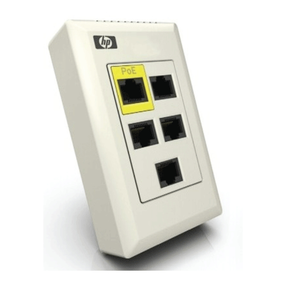
1 Preparing for installation Identifying components The following sections identify the various connectors and LEDs on the access device. Figure 1 Interface connectors and status LEDs 1: Reset button 7: Port 5 (Pass through) 2: Port 1 (with PoE) 8: Status LEDs right: P2, P4, PSE, Wi-Fi 3: Port 2 9: Uplink port Punchdown block 4: Port 3... - Page 6 Rear interfaces Description Uplink port (RJ-45 or punch-down Auto-sensing 10/100 Mbps Ethernet port with both an RJ-45 connector and block) punch-down block. Only one connector can be used at a time. Managed by the access device. Ports 1, 2, 3, and 4 are connected to the Uplink port by way of the internal Ethernet switch.
-
Page 7: Integrated Switch
Integrated switch Ports 1 to 4 and the Uplink port are connected to the built-in Ethernet switch. Each port on the switch can be a member of a VLAN. These port-based VLANs let you reduce broadcast traffic and increase network security. Reset button The reset button is located to the left of Port 1. -
Page 8: Power
The access device will be powered off by the PoE power source if there is an over-current situation. The HP Switch 2610 series features several models with PoE support that can be used in conjunction with the access device to build a cost-effective wireless networking infrastructure. - Page 9 Cabling: You must use the appropriate cables, and where applicable, surge protection, for your given region. For compliance with EN55022 Class-B emissions requirements use shielded Ethernet cables. Country of use: In some regions, you are prompted to select the country of use during setup. Once the country has been set, the controller will automatically limit the available wireless channels, ensuring compliant operation in the selected country.
-
Page 10: Installing
2. Use a screwdriver to pry off trim panel here. Installing the access device Install the access device as directed in the MSM317 Installation Guide provided with the unit and available online. The Installation Guide describes how to physically install a factory-default access device in an electrical outlet box and make basic connections. -
Page 11: Connecting Cables To The Access Device
Status LEDs The status LEDs are located to the left of Port 2 and to the right of Port 4. When the access device is fully installed, the status LEDs are not visible because they are covered by the trim panel. See Figure 1 (page 5) for the location of the LEDs. -
Page 12: Additional Configuration
Additional configuration For detailed information on how to configure and manage the access device, see “Initially configuring” (page 13) in this guide and also “Working with controlled APs” in the MSM7xx Controllers Configuration Guide. Installing... -
Page 13: Initially Configuring
3 Initially configuring IMPORTANT: The access device is part of the HP MSM family of wireless networking products. As such, it shares many of the same configuration options available on other MSM APs, and is configured in the same way by using the management tool on a controller. See the MSM7xx... -
Page 14: Directly Provisioning The Access Device
IP address, however). For complete details, see Working with Controlled APs in the MSM7xx Controllers Configuration Guide. Directly provision the access device: In its factory default state, the access device provides a provisioning menu with the same options that are available when using a controller to provision the access device. - Page 15 Click Provision at the bottom of the home page and provision the access device via settings on the Connectivity and Discovery pages. This is discussed in detail in the following sections. Connectivity page Use the Connectivity page to define addressing settings for the Uplink port. 1.
- Page 16 Assign IP address via Select how the access device will obtain an IP address for the Uplink port. DHCP client Enable this option to have the Uplink port act as a DHCP client and request an IP address from a DHCP server. The access device sends DHCP requests on the specified VLAN if defined. If no VLAN is defined, the request is sent untagged.
-
Page 17: Discovery Page
Username Username that the access device will use inside the TLS tunnel. Password / Confirm password Password assigned to the access device. Anonymous Name used outside the TLS tunnel by all three EAP methods. If this field is blank, then the value specified for Username is used instead. -
Page 18: Location Page
name field on this page blank, then the DHCP-assigned domain name is appended to the specified names instead. Discover using IP address When this option is enabled the access device attempts to discover a controller using the IP addresses in the order that they appear in this list. Location page You can optionally use the Location page to record a reminder as to where your are physically installing the access device. - Page 19 The Switch port page presents different options depending on how you open it. If you select Controller > Controlled APs >> Configuration > Switch ports, you see the following page: If you select Controller > Controlled APs > [group] >> Configuration > Switch ports, you see the following page: If you select Controller >...
-
Page 20: Port Configuration Page
Name Name assigned to the port. Select the name to edit port settings. Enabled Yes: The port can transmit and received data traffic. No: The port cannot transmit or received data traffic. VLAN Lists any VLAN IDs assigned to the port. If the port is configured to support Uplink tagging the VLAN is followed by an asterisk (*). - Page 21 Each configuration option on this page is discussed in detail in the sections that follow. Settings Port settings Port name Friendly name assigned to the port. Flow control When this option is enabled, the access device uses Ethernet flow control when exchanging traffic with a connected device.
-
Page 22: Quality Of Service
packets and simply drops them. Loop protection has no such limitation, and can be used to prevent loops on unmanaged switches. Quality of service The quality of service (QoS) feature provides a number of different mechanisms to prioritize traffic from the switch ports when it is forwarded on the Uplink port. This is useful when the access device handles traffic from multiple devices that have different data flow requirements. - Page 23 Priority lookup option QoS marking on Queue to which traffic Is a VLAN defined on QoS marking on traffic incoming traffic is assigned the port? exiting the Uplink port None Remarked as 802.1p based on Default traffic priority setting or the LLDP Network Policy TLV if defined*.
-
Page 24: Rate Limiting
DiffServ (Differentiated Services) This mechanism classifies traffic based on the value of the Differentiated Services (DS) codepoint field in IPv4 and IPv6 packet headers (as defined in RFC2474). The codepoint is composed of the six most significant bits of the DS field. Queue DiffServ (DS codepoint value) <= 34... -
Page 25: Mac Filter
Egress rate Set the maximum rate at which this port will send traffic. This rate applies to all outgoing traffic (broadcast, multicast, and unicast). Traffic in excess of the set rate is delayed. Traffic Indicates the type of traffic to which egress rate limiting applies. It is set to All (broadcast, multicast, and unicast), and cannot be changed. -
Page 26: Send Network Policy Tlv
Under Global, specify a name to identify the MAC address list. Under MAC list, specify the MAC address and mask that you want to match, then select Add. For example: The following definition matches a single MAC address: MAC address=00:03:52:07:2B:43 Mask=FF:FF:FF:FF:FF:FF By changing the last digit of the mask, the definition now matches a range of MAC addresses from 00:03:52:07:2B:40 to 00:03:52:07:2B:4F: MAC address=00:03:52:07:2B:43 Mask=FF:FF:FF:FF:FF:F0... - Page 27 Application type profiles Application type This release only supports the Voice application type VLAN ID Specify a VLAN ID for this profile. This VLAN will be assigned to the switch port when the profile is used. VLAN tagging Tagged: The VLAN is tagged. Untagged: The VLAN is untagged.
-
Page 28: Vlan
Specify a value for the Differentiated Services codepoint (DSCP) field in IPv4 and IPv6 packet headers (as defined in RFC2474). The codepoint is composed of the six most-significant bits of the DS field. DiffServ codepoint (DSCP) value QoS queue > 33 26 - 33 18 - 25 1 - 17... - Page 29 if two ports are set to Uplink tagging with different Primary VLAN IDs, then traffic cannot be exchanged between the two ports. For example, if the ports are configured as follows: Port Configuration Incoming traffic Outgoing traffic Uplink port Primary VLAN=Uplink Only untagged traffic is Untagged.
- Page 30 When this option is disabled: If the port is bound to an access-controlled VSC, the dynamically assigned VLAN is applied on the controller and not on the access device. The dynamic VLAN will override the VLAN settings on the VSC egress mapping on the controller. See “Example 4.
- Page 31 Allow dynamic VLAN assignment=On VLAN configuration example The following diagram illustrates how traffic is handled by the switch for a sample configuration. Refer to the descriptions that follow for details. MSM317 Switch Port 1 Primary VLAN = Tagged VLAN 10...
- Page 32 P o r t N e t w R A D I U s e r S e r v e User A Private network MSM317 Notebook User gains access to Untagged Port 2 VLAN=30 resources on the private -Wired -Primary VLAN=Untagged network.
- Page 33 P o r t N e t w R A D I U s e r S e r v e User A Private network MSM317 Notebook User gains access to Untagged VLAN=30 Port 2 resources on the private -Wired -Primary VLAN=Untagged network.
- Page 34 U p l i n P o E w i t h P o r t U s e r Private network User A MSM7xx Controller MSM317 Notebook User gains access to Untagged Port 2 VLAN=10 VSC: Guest VLAN=30 resources on the private...
-
Page 35: Vsc Binding
S w i t c U p l i n P o E w i t h P o r t U s e r User A Private network MSM317 MSM7xx Controller Notebook User gains access to Untagged VLAN=10 VSC: Guest VLAN=30... - Page 36 -Default settings -Default settings In this scenario, Port 2 is bound to the default VSC which is called HP. Authentication occurs using the local user accounts on the controller (via 802.1X or HTML-based logins). Once authenticated, user A gains access to resources on the private network according to the configuration of the controller public access interface feature.
- Page 37 U p l i n P o E w i t h P o r t U s e r User A Private network MSM7xx Controller MSM317 User gains access to Notebook VSC: Guest Untagged Port 2 VLAN=10 Untagged resources on the private...
- Page 38 Configuration of the VLAN on the controller is done by defining a network profile with VLAN 10 and binding it to the LAN port on the controller. Define the new network profile on the Controller >> Network > Network profiles page and assign VLAN 10 to it. Map the new network profile to the LAN port using the Controller >>...
- Page 39 P o r t 1 1 b / 8 0 2 . U s e r U s e r VOIP Phone Private network MSM7xx Controller MSM317 Mini-bar Mini-bar traffic is sent onto Port 1 VSC: Equipment Untagged VLAN=99 Untagged the private network.
- Page 40 Since the Equipment VSC is not the default VSC, a VLAN definition must be assigned to the port to ensure that traffic is properly routed from the access device to the Equipment VSC on the controller. Key configuration settings for Port 1 are as follows: Configuration of the VLAN on the controller is done by defining a network profile with VLAN 99 and binding it to the LAN port on the controller.
- Page 41 Key configuration settings for the VSC are as follows: User A Wired guests, as illustrated by user A, connect to Port 2, which is bound to the VSC named Guest. Authentication occurs via HTML, using the local user accounts on the controller. Once authenticated, user A gains access to resources on the private network according to the configuration of the public access interface feature on the controller.
- Page 42 Because the VLAN is only used to route traffic to the appropriate VSC on the controller, it does not require an IP address. Key configuration settings for the VSC are as follows: User B Wireless guests, illustrated by user B, connect to the access device radio using the SSID Guest. This SSID is defined in the VSC named Guest which is bound to the access device using Controlled APs >...
- Page 43 Binding to a non-access-controlled VSC When a port is bound to a non-access-controlled VSC, the controller is used for authentication tasks only. Authentication can occur by checking the user's MAC address or via 802.1X. Access control must then be performed by another device on the network, or not at all. Example 1.
- Page 44 P r i v a o r k P o r t N e t w U s e r User A Private network MSM317 Notebook User gains access to Untagged Port 2 Untagged resources on the private -Wired -Primary VLAN=Untagged network.
- Page 45 Key configuration settings for the VSC are as follows: If the private network is operating on a VLAN, you can assign a VLAN to Port 2. In the following scenario, once authenticated, the user gains direct access to any resources on the private network using VLAN 10.
-
Page 46: Authentication
P r i v a o r k P o r t N e t w U s e r User A Private network MSM317 Notebook User gains access to Untagged VLAN=10 Port 2 resources on the private -Wired -Primary VLAN=Uplink tagging network. -
Page 47: Viewing Status Information
NOTE: Only one authenticated MAC address is supported per port. This means that: If multiple devices are connect to a switch port via a hub, only one device (or user) can gain access at a time. A computer cannot be connected to the data port on an IP phone that is connected to a switch port. - Page 48 Access point list Status Green: The controller is synchronized. Red: The controller is not functioning normally. Refer to the Diagnostic column for details. Grey blinking: An action is pending for this controller. Sec. the Action column for details AP name Name assigned to the AP.
- Page 49 Diagnostic Indicates the status of the controller with regards to management by the team. Diagnostic Description Configured The controller is configured as part of the team. Detected The controller sent a discovery request to the team manager and the team manager has replied. Establishing tunnel A secure management connection is being established between the team manager and the controller.
-
Page 50: Diagnostic Information
Diagnostic information Provides more detailed information for any message that appears in the Overview Diagnostic column. Networking information - Controller Control channel Interface the controller is using to communicate with the manager. VLAN identifier VLAN the controller is using to communicate with the manager. MAC address Controller MAC address. -
Page 51: Wireless Clients
Wireless clients To see a list of all wireless clients connected to the access device and related status information, select the access device in the Network Tree under Controlled APs, then in the right pane select Overview > Wireless clients. For example: AP name Name of the AP with which the client station is associated. - Page 52 Port Indicates the port name and status. Green light: Port is active. Red light: Port is not active. Receive Packets: Number of packets received. Dropped: Number of received packets that were dropped. Errors: Number of packets received with errors. This can be caused by overruns, unaligned frames, bad CRCs, frame length violations, or late collisions.
-
Page 53: Bridge Port Statistics
Bridge port statistics To see the traffic forwarding tables for the bridge and the switch ports, select the access device in the Network Tree under Controlled APs, then in the right pane select Status > Bridge. For example: Bridge status State Current state of the bridge. -
Page 54: Bridge Forwarding Table
Identifies the MAC address to be matched. Traffic addressed to this address is forwarded on the corresponding port. VSC ID Internal identifier assigned to a VSC. For use by HP support. VLAN Identifies the VLAN that the MAC address is associated with. -
Page 55: A Regulatory Information
All HP devices are designed to be compliant with the rules and regulations in locations they are sold and will be labeled as required. Any changes or modifications to HP Equipment, not expressly approved by HP, could void the user's authority to operate this device. Unauthorized modifications or attachments could cause damage and may violate local radio regulations in your region. -
Page 56: Notice For Canada
R&TTE Directive 1999/5/EC. Compliance with these directives implies conformity to harmonized European standards (European Norms) that are listed on the EU Declaration of Conformity that has been issued by HP for this device. Countries of Operation & Conditions of Use... -
Page 57: Notice For Brazil
Notice for Brazil Aviso aos usuários no Brasil Este equipamento opera em caráter secundário, isto é, não tem direito à proteção contra interferência prejudicial, mesmo de estações do mesmo tipo, e não pode causar interferência a sistemas operando em caráter primário. Notice for Japan Notice for Korea (warning for wireless equipment) -
Page 58: B Recycle Statements
B Recycle statements Waste Electrical and Electronic Equipment (WEEE) statements English recycling notice Disposal of waste equipment by users in private household in the European Union This symbol means do not dispose of your product with your other household waste. Instead, you should protect human health and the environment by handing over your waste equipment to a designated collection point for the recycling of waste electrical and electronic equipment. -
Page 59: Estonian Recycling Notice
Estonian recycling notice Äravisatavate seadmete likvideerimine Euroopa Liidu eramajapidamistes See märk näitab, et seadet ei tohi visata olmeprügi hulka. Inimeste tervise ja keskkonna säästmise nimel tuleb äravisatav toode tuua elektriliste ja elektrooniliste seadmete käitlemisega egelevasse kogumispunkti. Küsimuste korral pöörduge kohaliku prügikäitlusettevõtte poole. Finnish recycling notice Kotitalousjätteiden hävittäminen Euroopan unionin alueella Tämä... -
Page 60: Italian Recycling Notice
Italian recycling notice Smaltimento di apparecchiature usate da parte di utenti privati nell'Unione Europea Questo simbolo avvisa di non smaltire il prodotto con i normali rifi uti domestici. Rispettare la salute umana e l'ambiente conferendo l'apparecchiatura dismessa a un centro di raccolta designato per il riciclo di apparecchiature elettroniche ed elettriche. -
Page 61: Romanian Recycling Notice
Romanian recycling notice Casarea echipamentului uzat de către utilizatorii casnici din Uniunea Europeană Acest simbol înseamnă să nu se arunce produsul cu alte deşeuri menajere. În schimb, trebuie să protejaţi sănătatea umană şi mediul predând echipamentul uzat la un punct de colectare desemnat pentru reciclarea echipamentelor electrice şi electronice uzate.