HP MSR2000 Series Manual
Hide thumbs
Also See for MSR2000 Series:
- Configuration manual (455 pages) ,
- High availability configuration manual (91 pages) ,
- Configuration manual (364 pages)
Table of Contents
Advertisement
Quick Links
Product overview
Table 1 HP MSR 2000, 3000 and 4000 Router Series models
Product code
JG$
JG
$
J*$
JG$
JG$
JG$
J*$
For regulatory identification purposes, the products are assigned Regulatory Model
x
For regulatory identification purposes, the HP 5920AF-24XG and HP 5920AF-24XG TAA products
are assigned Regulatory Model Numbers (RMN). The Regulatory Model Numbers for these
Numbers (RMN). The Regulatory Model Numbers for these products are listed below.
products are listed below. These regulatory numbers should not be confused with the marketing
These regulatory numbers should not be confused with the marketing name (HP description)
names HP 5920AF, or product numbers JG296A and JG555A.
or product numbers (product code).
Product code
JG411A
JG296A
______________________________________________________________________________________
JG555A
JG409A
x
For
regulatory
______________________________________________________________________________________
5900AF-48XG-4QSFP+ TAA products are assigned Regulatory Model Numbers (RMN). The
JG406A
Regulatory Model Numbers for these products are listed below. These regulatory numbers should
______________________________________________________________________________________
not be confused with the marketing names HP 5900AF, or product numbers JC772A and JG554A.
JG405A
Product code
______________________________________________________________________________________
JG404A
JC772A
______________________________________________________________________________________
JG554A
JG403A
x
______________________________________________________________________________________
For regulatory identification purposes, the HP 5900AF-48XGT-4QSFP+ Switch is assigned a
regulatory model number (RMN) BJNGA-AD0018. This regulatory number should not be confused
JG402A
with the marketing name HP 5900AF, or product code JG336A.
x
For regulatory identification purposes, the HP 5900AF-48G-4XG-2QSFP+ Switch is assigned a
regulatory model number (RMN) BJNGA-AD0017. This regulatory number should not be confused
with the marketing name HP 5900AF, or product code JG510A.
HP description
+3 065 $& 5RXWHU
+3 065 $& 5RXWHU
+P 065 $& 5RXWHU
+3 065 5RXWHU
+3 065 5RXWHU
+3 065 5RXWHU &KDVVLV
+3 065 5RXWHU &KDVVLV
RMN
BJNGA-BB0009
BJNGA-AC0007
BJNGA-AC0007
BJNGA-BB0008
identification
purposes,
BJNGA-BB0007
BJNGA-BB0011
RMN
BJNGA-BB0006
BJNGA-AD0016
BJNGA-AD0016
BJNGA-BB0010
BJNGA-BB0005
1
Alias
HP 065
+3 065
HP 065
+3 065
+3 065
+3 065
+3 065
HP description
HP MSR2003 AC Router
HP 5920AF-24XG Switch
HP 5920AF-24XG TAA Switch
HP MSR3012 AC Router
the
HP
5900AF-48XG-4QSFP+
HP MSR3024 AC Router
HP MSR3044 Router
HP description
HP MSR3064 Router
HP 5900AF-48XG-4QSFP+ Switch
HP 5900AF-48XG-4QSFP+ TAA Switch
HP MSR4060 Router Chassis
HP MSR4080 Router Chassis
and
HP
Advertisement
Table of Contents
Troubleshooting

Related Manuals for HP MSR2000 Series


Summary of Contents for HP MSR2000 Series
- Page 1 BJNGA-BB0007 HP MSR3024 AC Router Regulatory Model Numbers for these products are listed below. These regulatory numbers should ______________________________________________________________________________________ not be confused with the marketing names HP 5900AF, or product numbers JC772A and JG554A. JG405A BJNGA-BB0011 HP MSR3044 Router Product code...
-
Page 2: Table Of Contents
Contents Preparing for installation ············································································································································· 1 Safety recommendations ·················································································································································· 1 Safety symbols ·························································································································································· 1 General safety recommendations ··························································································································· 1 Electricity safety ························································································································································ 1 Laser safety ································································································································································ 1 Examining the installation site ········································································································································· 1 Temperature and humidity ·······································································································································... - Page 3 Powering on the router ······································································································································· xxix Displaying boot information ································································································································ xxx Examining the router after power-on ·················································································································· xxx Configuring basic settings for the router ··················································································································· xxxi Replacement procedure ·················································································································································i Replacing a power module ··············································································································································· i ...
-
Page 4: Preparing For Installation
Preparing for installation Safety recommendations Safety symbols When reading this document, note the following symbols: WARNING means an alert that calls attention to important information that if not understood or followed can result in personal injury. CAUTION means an alert that calls attention to important information that if not understood or followed can result in data loss, data corruption, or damage to hardware or software. -
Page 5: Temperature And Humidity
Temperature and humidity You must maintain a proper temperature and humidity in the equipment room. Lasting high relative humidity tends to cause poor insulation, electricity creepage, mechanical property change of materials, and corrosion of metal parts. Lasting low relative humidity is likely to result in loose screws due to washer contraction, and even ... -
Page 6: Esd Prevention
Figure 1 Airflow through the MSR3012/3024 chassis Figure 2 Airflow through the MSR3044/3064 chassis To ensure good ventilation, the following requirements must be met: The air inlet and outlet vents are not blocked, and leave at least 10 cm (3.94 in) of clearance. ... -
Page 7: Emi
Place the removed memory module, CF card, or interface module on an antistatic workbench, with the face upward, or put it into an antistatic bag. Touch only the edges, instead of electronic components when you observe or move a removed memory module, CF card, or interface module. -
Page 8: Installation Tools
For heat dissipation and device maintenance, make sure the front and rear of the rack are at least 0.8 m (2.62 ft) away from walls or other devices, and the headroom in the equipment room is no less than 3 m (9.84 ft). Installation tools Flathead screwdriver Phillips screwdriver... - Page 9 Item Requirements Result Temperature 0°C to 45°C (32°F to 113°F). Relative humidity 5% to 90% (noncondensing). Dust concentration ≤ 3 × 10 particles/m Cleanness No visible dust on desk within three days. The equipment and floor are well grounded. ...
- Page 10 Item Requirements Result Installation accessories supplied with the router. Tools User supplied tools. Documents shipped with the router. Reference Online documents.
- Page 11 Contents Installing the router ·························································································································································i Installation prerequisites ···················································································································································· i Installation flow ·································································································································································· i Installing the router ··························································································································································· iii Installing an air filter ··············································································································································· iii Mounting the router on a workbench ···················································································································· iii Installing the router in a 19-inch rack ··················································································································· iv ...
-
Page 12: Installing The Router
Keep the tamper-proof seal on a mounting screw on the chassis cover intact, and if you want to open the chassis, contact HP for permission. Otherwise, HP shall not be liable for any consequence. Installation prerequisites You have read "Preparing for installation" carefully. - Page 13 Figure 3 Installation flow...
-
Page 14: Installing The Router
Installing the router Installing an air filter No air filter is provided with the router. Purchase one yourself. Only the MSR3044 and MSR3064 support air filters. To install an air filter: Face the left side (side of the inlet vents) of the router. Install the upper and lower guide rails of the air filter to the chassis. -
Page 15: Installing The Router In A 19-Inch Rack
IMPORTANT: Ensure good ventilation and 10 cm (3.94 in) of clearance around the chassis for heat dissipation. Avoid placing heavy objects on the router. To mount the router on a workbench: Make sure the workbench is clean, stable, and properly grounded. Place the router upside down on the workbench and attach the rubber feet to the four round holes in the chassis bottom. - Page 16 Figure 8 Front mounting brackets Figure 9 Rear mounting brackets Installing the router to the rack WARNING! The mounting brackets can only support the weight of the router. To avoid damage to the router, do not place any objects on the router. Use a front mounting bracket to mark the positions of cage nuts, making sure they are at the same level.
- Page 17 Figure 10 Marking the positions of cage nuts for the front mounting brackets Figure 11 Marking the positions of cage nuts for the rear mounting brackets...
- Page 18 Insert one edge of a cage nut into the hole. Use a flat-blade screwdriver to compress the other edge of the cage nut, and then push the cage nut fully into the hole. Repeat step 3 to install other cage nuts to all the marked positions on the rack posts. Figure 12 Installing a cage nut Attach the rear mounting brackets to the rack and fasten the screws.
- Page 19 Figure 14 Attaching the rear mounting brackets (router depth smaller than rack depth) Attach the front mounting brackets to the chassis and fasten the screws. Attach load-bearing screws to the rear of the chassis. Figure 15 Attaching the front mounting brackets and load-bearing screws to the MSR3012/3024 Figure 16 Attaching the front mounting brackets and load-bearing screws to the MSR3044 viii...
- Page 20 Figure 17 Attaching the front mounting brackets and load-bearing screws to the MSR3064 Place the router on the rack, making sure the load-bearing screws hang on the rear mounting brackets. Secure the chassis in the rack by attaching the front mounting brackets with proper pan head screws onto the back.
-
Page 21: Grounding The Router
Figure 18 Mounting the router to the rack Grounding the router WARNING! Correctly connecting the router grounding cable is crucial to lightning protection and EMI protection. IMPORTANT: The resistance reading should be smaller than 5 ohms between the chassis and the ground. Grounding the router through the grounding terminal on the rack IMPORTANT:... - Page 22 To connect the grounding cable: Remove the two grounding screws from the rear panel of the chassis. Attach the grounding screw to the ring terminal of the grounding cable. See Figure Use a Phillips screwdriver to fasten the grounding screw into the grounding screw hole. Remove the grounding screw from the grounding point on the rack.
- Page 23 Figure 20 Grounding the router through the grounding terminal on the rack...
-
Page 24: Grounding The Router With A Grounding Strip
Grounding the router with a grounding strip If a grounding strip is available at the installation site, connect the grounding cable to the grounding strip. Follow the same procedures in "Grounding the router through the grounding terminal on the rack" to connect the grounding cable. -
Page 25: Grounding The Router With A Grounding Conductor Buried In The Earth Ground
Figure 21 Grounding the router with a grounding strip Grounding the router with a grounding conductor buried in the earth ground If the installation site has no grounding strips, but earth ground is available, hammer a 0.5 m (1.64 ft) or longer angle iron or steel tube into the earth ground to serve as a grounding conductor. -
Page 26: Installing A Dsic
Figure 22 Removing the filler panel Figure 23 Installing the SIC Installing a DSIC CAUTION: DSIC interface modules are not hot swappable. Make sure the router is powered off before installing a DSIC. To install a DSIC: Remove the screws on the filler panel on a SIC slot of an MSR3024, 3044, or 3064 to remove the filler panel. -
Page 27: Installing An Hmim
Figure 24 Removing the filler panel Figure 25 Removing the slot divider Insert the DSIC into the slot and push it along the slide rails until it makes close contact with the backplane of the router. Figure 26 Installing a DSIC Fasten the captive screws to secure the DSIC. -
Page 28: Installing A Mim
IMPORTANT: You can install an HMIM when the router is powered on. However, before replacing an HMIM when the slotnumber router is powered on, you must execute the remove hmimslot command. An HMIM interface module can be 1U or 0.5U. This section takes a 0.5U interface module for example. When you install a 1U interface module to an MSR router, remove the filler panels of the target slot and the neighboring slot above. - Page 29 IMPORTANT: To install a MIM, install it to the HMIM adapter and then insert it into the HMIM slot. You can install a MIM when the router is powered on. However, before replacing a MIM when the router slotnumber is powered on, you must execute the remove hmimslot command.
-
Page 30: Connecting The Router To The Network
Connecting the router to the network Connect the router to the network before powering on the router. This section describes how to connect the router to the network through Ethernet cables. Connecting an Ethernet cable Plug one end of an Ethernet twisted pair cable into the copper Ethernet port (RJ-45 port) to be connected on the router. -
Page 31: Installing A Cf Card
connector at one end of another fiber cable into the Tx port of the router and the LC connector at the other end to the Rx port of the peer device. Examine the Ethernet port LED after connection. Figure 32 Connecting an optical fiber Installing a CF card Open the CF card cover by pressing the spring clip. -
Page 32: Logging In Through The Console Port
Logging in through the console port Connecting a console cable You can log in only through the console port by using a console or USB console cable the first time you log in to your router. To connect a console cable: Plug the DB-9 female connector to the serial port of the configuration terminal. -
Page 33: Setting Terminal Parameters
Figure 35 Connecting the USB cable Setting terminal parameters This section uses a PC with Windows XP as an example. To set terminal parameters: Select Start > All Programs > Accessories > Communications > HyperTerminal. The Connection Description dialog box appears. Figure 36 Connection description Select the serial port to be used from the Connect using list, and click OK. - Page 34 Figure 37 Setting the serial port used by the HyperTerminal connection Set Bits per second to 9600, Data bits to 8, Parity to None, Stop bits to 1, and Flow control to None, and click OK. Figure 38 Setting the serial port parameters Select File >...
-
Page 35: Installing A Power Module
Figure 39 HyperTerminal window On the Settings tab, set the emulation to VT100 or Auto detect and click OK. Figure 40 Setting terminal emulation in test Properties dialog box Installing a power module xxiv... - Page 36 IMPORTANT: Only the MSR3044 and MSR3064 support power modules. Installing an AC/DC power module Face the front of the router and locate the slot to be used. Loosen the captive screws with a Phillips screwdriver to remove the filler panel from the slot. Keep the removed filler panel for future use.
-
Page 37: Connecting The Power Cord
Holding the handle of the power module with one hand and supporting the bottom of the power module with the other hand, insert the power module slowly along the slide rails until it makes close contact with the backplane. Use a Phillips screwdriver to fasten the captive screws on the two sides of the power module. Figure 43 Installing a PoE power module Connecting the power cord Connecting an AC power cord... -
Page 38: Connecting A Dc Power Cord
Figure 45 Connecting an AC power cord to an MSR3044/3064 router Connecting a DC power cord WARNING! Pay attention to the mark on a power cord to avoid connection errors. The MSR3012/3024 and MSR3044/3064 use different DC connectors, but the power cord connection procedures are the same. -
Page 39: Connecting An Rps Power Cord
Figure 47 Connecting a DC power cord for an MSR3044/3064 Connecting an RPS power cord The MSR3012 and MSR3024 offer remote power supply (RPS) support. As an external power supply, RPS can provide power supply for the device in case of power module abnormality. It enhances the reliability of the device. -
Page 40: Verifying The Installation
Figure 49 Connecting the RPS power cord Verifying the installation After you complete the installation, verify that: There is enough space for heat dissipation around the router, and the rack or workbench is stable. USB devices and interface modules are properly installed. The router, rack, and power cords are properly grounded. -
Page 41: Displaying Boot Information
System is starting... Booting Normal Extend BootWare..The Extend BootWare is self-decompressing..Done. **************************************************************************** HP MSR3064 BootWare, Version 1.01 **************************************************************************** Copyright (c) 2004-2012 Hangzhou HP Technologies Co., Ltd. Compiled Date : Sep 25 2012 CPU ID : 0x4 Memory Type : DDR3 SDRAM... -
Page 42: Configuring Basic Settings For The Router
Configuring basic settings for the router After the router is powered on for the first time, configure the basic settings for the router. For more information, see HP MSR Routers Fundamentals Configuration Guide (V7) and HP MSR Routers Fundamentals Command Reference (V7). - Page 43 Contents Replacement procedure ·················································································································································i Replacing a power module ··············································································································································· i Replacing an air filter ························································································································································ i Replacing a CF card ························································································································································· ii Replacing a SIC ······························································································································································· iii Replacing a DSIC ····························································································································································· iv Replacing an HMIM ························································································································································· v ...
-
Page 44: Replacement Procedure
Keep the tamper-proof seal on a mounting screw on the chassis cover intact, and if you want to open the chassis, contact HP for permission. Otherwise, HP shall not be liable for any consequence. Replacing a power module The replacement procedure of an AC power module is the same as a DC power module. This section uses an AC power module as an example. -
Page 45: Replacing A Cf Card
Figure 51 Removing an air filter Install a new air filter. For the installation procedure, see "Installing the router." To remove the slide rails, completely loosen the fastening screws of the slide rails. To install new slide rails, see "Installing the router." Figure 52 Removing slide rails Replacing a CF card CAUTION:... -
Page 46: Replacing A Sic
Figure 53 Removing the CF card Install a new CF card. For the installation procedure, see "Installing the router." If you do not install a new CF card, close the CF card cover. Replacing a SIC Completely loosen the captive screws of the SIC. Gently pull the SIC out along the slide rails. -
Page 47: Replacing A Dsic
Figure 55 Installing a filler panel Replacing a DSIC Completely loosen the captive screws of the DSIC. Gently pull the DSIC out along the slide rails. If you need to install SIC or DSIC interface modules, see "Installing the router" for the installation procedure. -
Page 48: Replacing An Hmim
Figure 57 Installing a slot divider Figure 58 Installing filler panels Replacing an HMIM WARNING! You can replace an HMIM when the router is powered on. However, before replacing an HMIM when the slotnumber router is powered on, you must execute the remove hmimslot command. -
Page 49: Replacing A Mim
Figure 59 Pulling the HMIM out of the slot Figure 60 Installing a filler panel Replacing a MIM WARNING! You can replace a MIM when the router is powered on. However, before replacing a MIM when the router slotnumber is powered on, you must execute the remove hmimslot command. - Page 50 Figure 61 Removing a MIM and the HMIM adapter Completely loosen the captive screws of the MIM, remove the screws that secure the MIM to the HMIM adapter, and pull the MIM out of the HMIM adapter along the slide rails. Keep the removed MIM for future use.
- Page 51 Contents Troubleshooting ······························································································································································i Troubleshooting the power supply system failure ··········································································································· i Troubleshooting fan failures ·············································································································································· i Troubleshooting the configuration system failures ········································································································· ii No display on the configuration terminal ·············································································································· ii Garbled characters on the configuration terminal ································································································ ii ...
-
Page 52: Troubleshooting
Keep the tamper-proof seal on a mounting screw on the chassis cover intact, and if you want to open the chassis, contact HP for permission. Otherwise, HP shall not be liable for any consequence. Troubleshooting the power supply system failure Symptom The router cannot be powered on. -
Page 53: Troubleshooting The Configuration System Failures
Troubleshooting the configuration system failures If the router operates properly after being powered on, the boot information is displayed on the configuration terminal. If the configuration system is faulty, the configuration terminal displays garbled characters or does not display anything. No display on the configuration terminal Symptom After the router is powered on, the console terminal does not display anything. -
Page 54: Solution
Execute the save command after modifying the user password to save the new password. [Sysname] save NOTE: HP recommends that you save the modification as the default configuration file. Troubleshooting interface module, cable, and connection failure Symptom After an interface module is installed and the router is powered on, the LEDs on the interface module panel indicate that the interface module is operating improperly. - Page 55 Solution Verify that the interface module makes good contact with the rear panel of the router slot. Verify that the router supports the interface module. Verify that the interface module is installed in the specified router slot. Verify that a correct cable is used. Verify that the cable is correctly connected.
- Page 56 Contents Appendix A Chassis views and technical specifications ····························································································i Chassis views ····································································································································································· i MSR3012 AC ···························································································································································· i MSR3012 DC ··························································································································································· ii MSR3024 AC ··························································································································································· ii MSR3024 DC ·························································································································································· iii MSR3024 PoE ························································································································································· iv MSR3044 ··································································································································································...
-
Page 57: Appendix A Chassis Views And Technical Specifications
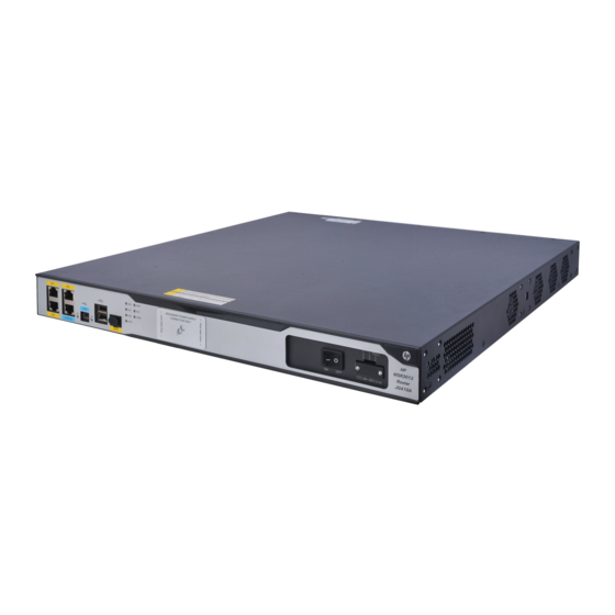
Appendix A Chassis views and technical specifications Chassis views The following figures are for illustration only. MSR3012 AC Figure 64 MSR3012 AC front view (1) Gigabit Ethernet port (GE1) (2) Gigabit Ethernet port (GE2) (3) USB console port (CON) (4) USB port 1 (5) SFP interface (SFP0) (6) RPS receptacle cover (7) Power switch... -
Page 58: Msr3012 Dc
MSR3012 DC Figure 66 MSR3012 DC front view (1) Gigabit Ethernet port (GE1) (2) Gigabit Ethernet port (GE2) (3) USB console port (CON) (4) USB port 1 (5) SFP interface (SFP0) (6) RPS receptacle cover (7) Power switch (8) DC-input power receptacle (9) USB port 0 (10) Console port/AUX port (11) Gigabit Ethernet port (GE0) -
Page 59: Msr3024 Dc
(4) RPS receptacle cover (5) Power switch (6) AC-input power receptacle (7) Power cord bail latch (8) SFP port (SFP0) (9) USB console port (CON) (10) Console port/AUX port (11) Gigabit Ethernet port (GE2) (12) Gigabit Ethernet port (GE1) (CON/AUX) (13) Gigabit Ethernet port (GE0) Figure 69 MSR3024 AC rear view (1) Grounding terminal... -
Page 60: Msr3024 Poe
Figure 71 MSR3024 DC rear view (1) Grounding terminal (2)SIC slot (slot 4) (3) SIC slot (slot 3) (4) HMIM slot (slot 6) (5) HMIM slot (slot 5) (6) SIC slot (slot 1) (7) SIC slot (slot 2) MSR3024 PoE Figure 72 MSR3024 PoE front view (1) CF card cover (2) USB port 0... -
Page 61: Msr3044
MSR3044 Figure 74 MSR3044 front view (1) SIC slot (slot 4) (2) SIC slot (slot 3) (3) SIC slot (slot 2) (4) USB port 0 (5) USB port 1 (6) SIC slot (slot 1) (7) Gigabit Ethernet port (GE1) (8) Gigabit Ethernet port (GE2) (9) USB console port (CON) (10) Console port/AUX port (11) Gigabit Ethernet port (GE0) -
Page 62: Msr3064
MSR3064 Figure 76 MSR3064 front view (1) SIC slot (slot 4) (2)SIC slot (slot 3) (3) SIC slot (slot 2) (4) USB port 0 (5) USB port 1 (6) SIC slot (slot 1) (7) Gigabit Ethernet port (GE1) (8) Gigabit Ethernet port (GE2) (9) USB console port (CON) (10) HMIM slot (slot 5) (11) HMIM slot (slot 7) -
Page 63: Appearance Of Power Modules
Appearance of power modules AC power module Figure 78 AC power module (1) Captive screw (2) Power switch (3) Air outlet vent (4) Power receptacle DC power module Figure 79 DC power module (1) Captive screw (2) Power switch (3) Air outlet vent (4) Power receptacle... -
Page 64: Poe Power Module
PoE power module Figure 80 PoE power module (1) Captive screw (2) Power switch (3) Air outlet vent (4) Power receptacle Technical specifications Table 5 Technical specifications Item 36-10 36-20 36-40 36-60 CON/AUX ports USB console ports USB ports Gigabit Ethernet ports SIC/DSIC slots 2 SIC slots 4 SIC slots/2 DSIC slots... - Page 65 Item 36-10 36-20 36-40 36-60 Rated power for 125 W 125 W AC: 300 W AC: 300 W AC/DC power supply Rated power for PoE Not supported 275 W 750 W 750 W power supply Rated power for each 15.4 W PoE port RPS power 800 W...
- Page 66 Contents Appendix B LEDs ····························································································································································i Panel LEDs ··········································································································································································· i MSR3012 ··································································································································································· i MSR3024 ··································································································································································· i MSR3044 ·································································································································································· ii MSR3064 ·································································································································································· ii Power module LEDs ·························································································································································· iii Appearance ····························································································································································· iii LED description ································································································································································· iv ...
-
Page 67: Appendix B Leds
Appendix B LEDs Panel LEDs MSR3012 Figure 81 MSR3012 LEDs (1) Console port LED (2) USB console port LED (3) SFP port LED (SFP0) (4) Gigabit Ethernet port LED (GE0) (5) Gigabit Ethernet port LED (GE1) (6) Gigabit Ethernet port LED (GE2) (7) System LED (SYS) (8) Power supply LED (PWR) -
Page 68: Msr3044
MSR3044 Figure 83 MSR3044 LEDs (1) CF card LED (2) System LED (SYS) (3) Power supply LED (PWR) (4) PoE power supply LED (5) VPM (slot 0) LED (VPM0) (6) VPM (slot 1) LED (VPM1) (7) Gigabit Ethernet port LED (GE0) (8) SFP port LED (SFP0) (9) Gigabit Ethernet port LED (GE1) (10) SFP port LED (SFP1) -
Page 69: Power Module Leds
Power module LEDs Appearance Figure 85 AC power module LEDs (1) Power input LED (2) Power output LED Figure 86 DC power module LEDs (1) Power input LED (2) Power output LED Figure 87 PoE power module LEDs (1) Power input LED (2) Power output LED... -
Page 70: Led Description
LED description LEDs State Description Flashing green (8 Hz) The BootWare runs. Steady green The SDRAM is performing self-test. Comware has started with the configuration file and the router Flashing green (1 Hz) has booted up. Flashing yellow (1 Hz) The DDR3 SDRAM has failed the self-test. - Page 71 LEDs State Description No link is present on the SFP interface. No power input or the power input is faulty. AC OK Steady green The power is input properly. No power output or the power output is faulty. DC OK Steady green The power is output properly.
- Page 72 Contents Appendix C Slot arrangement ···································································································································· 1 ...
-
Page 73: Appendix C Slot Arrangement
Appendix C Slot arrangement Each of the MSR3000 routers provides slots for SIC and HMIM interface cards. On the MSR3024, MSR3044, and MSR3064, you can combine two SIC slots into one DSIC slot by removing the slot divider. The fixed ports on the MSR3000 panel are located in slot 0. Table 9 Slot arrangement on the MSR3000 routers Model Slot arrangement...