Fortinet FortiGate-7000F Series System Manual
Hide thumbs
Also See for FortiGate-7000F Series:
- System manual (63 pages) ,
- Manual (30 pages) ,
- Manual (32 pages)
Table of Contents
Advertisement
Quick Links
Advertisement
Table of Contents

Related Manuals for Fortinet FortiGate-7000F Series


Summary of Contents for Fortinet FortiGate-7000F Series
- Page 1 FortiGate-7081F System Guide FortiGate-7000F Series...
-
Page 2: Connecting To The Fortios Cli Of The Fim In Slot
FORTINET DOCUMENT LIBRARY https://docs.fortinet.com FORTINET VIDEO GUIDE https://video.fortinet.com FORTINET BLOG https://blog.fortinet.com CUSTOMER SERVICE & SUPPORT https://support.fortinet.com FORTINET TRAINING & CERTIFICATION PROGRAM https://www.fortinet.com/support-and-training/training.html NSE INSTITUTE https://training.fortinet.com FORTIGUARD CENTER https://fortiguard.com/ END USER LICENSE AGREEMENT https://www.fortinet.com/doc/legal/EULA.pdf FEEDBACK Email: techdoc@fortinet.com March 8, 2023 FortiGate-7081F 7.0.5 System Guide... -
Page 3: Table Of Contents
Mounting the FortiGate-7081F chassis in a four-post rack Mounting the FortiGate-7081F chassis in a two-post rack Inserting FIMs and FPMs Getting started with FortiGate-7081F Configuring the SLBC management interface Confirming startup status Multi VDOM mode Changing data interface network settings FortiGate-7081F System Guide Fortinet Technologies Inc. - Page 4 Fortinet Technologies Inc. Changing the FortiGate-7081F log disk and RAID configuration Resetting to factory defaults Restarting the FortiGate-7081F Managing individual FortiGate-7081F FIMs and FPMs Special management port numbers HA mode special management port numbers Managing individual FIMs and FPMs from the CLI Connecting to individual FIM and FPM CLIs of the secondary FortiGate-7081F in an HA configuration...
- Page 5 Fortinet Technologies Inc. Agência Nacional de Telecomunicações (ANATEL) – Brazil (for the FortiGate-7081F AC model) FortiGate-7081F System Guide...
-
Page 6: Change Log
Change log Fortinet Technologies Inc. Change log Date Change description March 8, 2023 Initial release. FortiGate-7081F System Guide... -
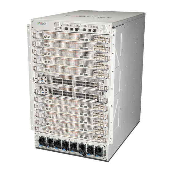
Page 7: Fortigate-7081F Chassis
An operating FortiGate-7081F includes two Fortinet Interface Modules (FIMs) in slots 1 and 2. The FortiGate-7081F supports the FIM-7921F and FIM-7941F. An operating FortiGate-7081F also includes up to six Fortinet Processor Modules (FPMs) in slots 3 to 8. The FortiGate- 7081F supports the FPM-7620F. ... -
Page 8: Fim-7941F Interface Module
The FIM-7941F interface module is a hot swappable module that provides data, management, and session sync/heartbeat interfaces, base backplane switching, hardware acceleration, and fabric backplane session-aware load balancing for a FortiGate-7000F series chassis. The FIM-7941F includes an integrated switch fabric, five NP7 FortiGate-7081F 7.0.5 System Guide... - Page 9 HA configuration, both chassis in the HA cluster must have the same FIMs. The FIM-7941F can be installed in any FortiGate-7000F series chassis in chassis hub/switch slots 1 or 2. The FIM- 7941F includes eighteen front panel 100GigE QSFP28 fabric channel data network interfaces (1 to 18) and two 400GigE QSFP-DD fabric channel data network interfaces (19 and 20).
-
Page 10: Fim-7921F Interface Module
The SSDs are accessible from the FIM-7921F front panel but should not be removed. The FIM-7921F can be installed in any FortiGate-7000F series chassis in chassis hub/switch slots 1 or 2. The FIM- 7921F includes eighteen front panel 100GigE QSFP28 fabric channel data network interfaces (1 to 18) and two 400GigE QSFP-DD fabric channel data network interfaces (19 and 20). -
Page 11: Fpm-7620F Processor Module
FortiGate-7081F chassis Fortinet Technologies Inc. FPM-7620F processor module The FPM-7620F processor module is a high-performance worker module that processes sessions load balanced to it by FIMs over the chassis fabric backplane. The FPM-7620F includes two 400Gbps data connections to the FIMs over the chassis fabric backplane and two 50Gbps management connections to the FIMs over base backplane. - Page 12 FortiGate-7081F chassis Fortinet Technologies Inc. FortiGate-7081F back panel Fan Tray 3 Fan Tray 2 Fan Tray 1 Chassis Ground Connector FortiGate-7081F 7.0.5 System Guide...
-
Page 13: Registering Your Fortigate-7081F
Fortinet customer services such as product updates and customer support. You must also register your product for FortiGuard services. Register your product by visiting https://support.fortinet.com. To register, enter your contact information and the serial numbers of the Fortinet products that you or your organization have purchased. FortiGate-7081F chassis schematic The FortiGate-7081F chassis schematic shows the communication channels between chassis components including the SMMs (MGMT1 and MGMT2), the FIMs (FIM1 and FIM2), and the FPMs (FPM3 to FPM8). -
Page 14: Chassis Hardware Information
FortiGate-7081F chassis Fortinet Technologies Inc. Each FIM and FPM and the SMMs have a Shelf Management Controller (SMC). These SMCs support IPMB communication between the active SMM and the FIMs and FPMs and other chassis components for storing and sharing sensor data that the SMM uses to control chassis cooling and power distribution. -
Page 15: Optional Accessories And Replacement Parts
FortiGate-7081F chassis Fortinet Technologies Inc. One set of 4-post rack mounting components. One set of 2-post rack mounting components. Sixteen M4x8 flat-head screws. Two M4x6 pan-head screws. Eight rubber feet. Two USB to RJ-45 RS-232 console cables. One RJ-45 Ethernet cable. -
Page 16: Cooling Fans, Cooling Air Flow, And Minimum Clearance
FortiGate-7081F chassis Fortinet Technologies Inc. Average Power Consumption 6100W Max Current 6 x 16A Heat Dissipation 26283KJ/h (24900BTU/h) Cooling fans, cooling air flow, and minimum clearance The FortiGate-7081F chassis contains three hot swappable cooling fan trays installed in the back of the chassis. Each fan tray includes three fans that operate together. -
Page 17: Cooling Air Flow And Required Minimum Air Flow Clearance
FortiGate-7081F chassis Fortinet Technologies Inc. Cooling Fan Tray Retention Retention Screw Screw Retention Retention Screw Screw Cooling air flow and required minimum air flow clearance When installing the chassis, make sure there is enough clearance for effective cooling air flow. The following diagram shows the cooling air flow through the chassis and the locations of fan trays. -
Page 18: Optional Air Filter
FortiGate-7081F chassis Fortinet Technologies Inc. FortiGate-7081F cooling air flow and minimum air flow clearance FortiGate-7081F chassis (side View) Front Back 100 mm 100 mm Trays Cool air Warm Air Intake Exhaust 675.5 mm Cool air enters the chassis through the chassis front panel and warm air exhausts out the back. For optimal cooling, allow 100 mm of clearance at the front and back of the chassis. -
Page 19: Power Consumption For Different Fim-7941F Fortigate-7081F Configurations
FortiGate-7081F chassis Fortinet Technologies Inc. Power consumption for different FIM-7941F FortiGate-7081F configurations The tables in this section provide information about how to calculate maximum power consumption for a FortiGate- 7081F system with two FIM-7941Fs and with two or six FPM-7620Fs. -
Page 20: Power Consumption For Different Fim-7921F Fortigate-7081F Configurations
FortiGate-7081F chassis Fortinet Technologies Inc. To completely power a FortiGate-7081F with two FIM-7941Fs and six FPM-7620Fs you would need three PSUs. You can add more PSUs to provide 3+1, 3+2, or 3+3 redundancy. Power consumption for different FIM-7921F FortiGate-7081F configurations The tables in this section provide information about how to calculate maximum power consumption for a FortiGate- 7081F system with two FIM-7921Fs and with two or six FPM-7620Fs. -
Page 21: Ac Psus And Supplying Ac Power To The Chassis
FortiGate-7081F chassis Fortinet Technologies Inc. Module Max power Number of Total max power (W) consumption (W) modules FPM-7620F 4296 Chassis (fans, SMMs 1340 1340 etc) Totals 6830 To completely power a FortiGate-7081F with two FPM-7620Fs and six FPM-7620Fs you would need three PSUs. You can add up to three more PSUs to provide 3+1, 3+2, or 3+3 redundancy. -
Page 22: Ac Psu Led States
FortiGate-7081F chassis Fortinet Technologies Inc. AC PSU LED states The PSU LED indicates whether the PSU is operating correctly and connected to power. State Description AC power not connected. If this LED is not lit, check to make sure the PSU is connected to a power feed. -
Page 23: Power Distribution Unit (Pdu) Requirements
7. Verify that the PSU status LED is solid green meaning that the PSU is powered up and operating normally. Power distribution unit (PDU) requirements Due to the power consumption FortiGate-7081F, Fortinet recommends the following PDU requirements if you are operating a FortiGate-7081F that contains two FIM-7921F and six FPM-7620Fs. -
Page 24: Turning On Fortigate-7081F Chassis Power
FortiGate-7081F chassis Fortinet Technologies Inc. 3. Connect the ground wire double-holed lug to the FortiGate-7081F chassis ground connector using the two M5x10 pan-head screws already attached to the ground connector. 4. Connect the other end for the ground wire to a data center ground connector. -
Page 25: Fortigate-7081F Hardware Assembly And Rack Mounting
The front mounting brackets are not required to mount the FortiGate-7081F in a two-post rack (see Mounting the FortiGate-7081F chassis in a two-post rack on page 31). FortiGate-7081F 7.0.5 System Guide Fortinet Technologies Inc. -
Page 26: Cable Bracket Kit
FortiGate-7081F hardware assembly and rack mounting Fortinet Technologies Inc. Cable bracket kit You can install the optional cable bracket kit to help manage the network cables connected to FIMs and FPMs installed in the FortiGate-7081F. Attach the cable bracket kit to the left and right front mounting brackets. - Page 27 FortiGate-7081F hardware assembly and rack mounting Fortinet Technologies Inc. Attaching network cables to the cable mount levers Installing horizontal cable mount levers From the inside, insert the mount lever through the top hole in the side bracket and extend it a short distance past the side bracket.
-
Page 28: Front Air Filter Kit
FortiGate-7081F hardware assembly and rack mounting Fortinet Technologies Inc. Front air filter kit You can attach a front air filter kit if the FortiGate-7081F will be installed in a dusty environment. The following diagrams show how to install the filter kit, special procedures for installing an FPM in slot 7, power cord management, and data cord management when the air filter kit is installed. -
Page 29: Power Cord Clamps
FortiGate-7081F hardware assembly and rack mounting Fortinet Technologies Inc. Front air filter kit data and power cable management Installing horizontal cable mount levers From the inside, insert the mount lever through the top hole in the side bracket and extend it a short distance past the side bracket. -
Page 30: Mounting The Fortigate-7081F Chassis In A Four-Post Rack
FortiGate-7081F hardware assembly and rack mounting Fortinet Technologies Inc. Mounting the FortiGate-7081F chassis in a four-post rack The FortiGate-7081F package includes a set of extendable rack mount trays that you can use to mount the chassis in a 4-post rack. Install the brackets to create a 4-post rack mount tray that the chassis will slide on to. Attach each side of the tray to the 4-post rack as shown below. -
Page 31: Mounting The Fortigate-7081F Chassis In A Two-Post Rack
FortiGate-7081F hardware assembly and rack mounting Fortinet Technologies Inc. Mounting the FortiGate-7081F chassis in a two-post rack The FortiGate-7081F package includes two mid mount trays and two mid-mount brackets that you can use to mount the chassis in a 2-post rack. As shown in the diagram, first attach the mid-mounting brackets to the chassis, them attach the mid mount trays to the rack, making sure to leave enough space above the trays for the chassis. -
Page 32: Inserting Fims And Fpms
FortiGate-7081F hardware assembly and rack mounting Fortinet Technologies Inc. Inserting FIMs and FPMs All FortiGate-7081F chassis are shipped with a protective front panel installed in the chassis to protect internal chassis components. This panel must be removed before you install FIMs and FPMs. -
Page 33: Getting Started With Fortigate-7081F
MGMT1: FIM01, 1-mgmt1, default IP address 192.168.1.99/24 one FIM, it should be installed in slot 1. All configuration changes must be made from the primary FIM GUI or CLI and not from the secondary FIM or the FPMs. FortiGate-7081F 7.0.5 System Guide Fortinet Technologies Inc. -
Page 34: Configuring The Slbc Management Interface
Configuration Sync Monitor also indicates if any of the FIMs or FPMs are not synchronized. The FortiGate-7081F uses the Fortinet Security Fabric for communication and synchronization between the FIMs and the FPMs and for normal GUI operation. By default, the Security Fabric is enabled and must remain enabled for normal operation. -
Page 35: Multi Vdom Mode
Getting started with FortiGate-7081F Fortinet Technologies Inc. Multi VDOM mode By default, when you first start up a FortiGate-7081F it is operating in Multi VDOM mode. The default Multi VDOM configuration includes the root VDOM and a management VDOM named mgmt-vdom. The management interfaces and the HA heartbeat interfaces are in mgmt-vdom and all the data interfaces are in the root VDOM. -
Page 36: Resetting To Factory Defaults
Getting started with FortiGate-7081F Fortinet Technologies Inc. execute disk raid rebuild The RAID is rebuilt at the current RAID level. Use the execute disk raid status command to show RAID status. The following command output shows the RAID status of the 4TByte SSDs configured for RAID-1. -
Page 37: Managing Individual Fortigate-7081F Fims And Fpms
SSL VPN), does not affect the special management port numbers. For example, to connect to the GUI of the FIM in slot 2 using HTTPS you would browse to https://192.168.1.99:44302. FortiGate-7081F 7.0.5 System Guide Fortinet Technologies Inc. -
Page 38: Ha Mode Special Management Port Numbers
Managing individual FortiGate-7081F FIMs and FPMs Fortinet Technologies Inc. To verify which FIM or FPM you have logged into, the GUI header banner and the CLI prompt shows its hostname. The System Information dashboard widget also shows the host name and serial number. The CLI prompt also shows the slot address in the format <hostname>... -
Page 39: Managing Individual Fims And Fpms From The Cli
Managing individual FortiGate-7081F FIMs and FPMs Fortinet Technologies Inc. Chassis and Slot Address HTTP HTTPS (443) Telnet SSH (22) SNMP (161) Slot Number (80) (23) Ch2 slot 7 FPM07 8027 44327 2327 2227 16127 Ch2 slot 5 FPM05 8025 44325... -
Page 40: Firmware Upgrades
Some firmware upgrades may take longer depending on factors such as the size of the configuration. Before beginning a firmware upgrade, Fortinet recommends that you perform the following tasks: Review the latest release notes for the firmware version that you are upgrading to. -
Page 41: Installing Firmware On Individual Fims Or Fpms
Firmware upgrades Fortinet Technologies Inc. 1. Log into the primary FIM and verify that it is running the expected firmware version. You can verify the firmware version running on the primary FIM from the System Information dashboard widget or by using the get system status command. -
Page 42: Upgrading The Firmware On An Individual Fpm
CLI of the FIM or FPM and restart it using the execute reboot command. If this does not solve the problem, contact Fortinet Support at https://support.fortinet.com. If you enter the diagnose sys confsync status | grep in_sy command before the FIM has completely restarted, it will not appear in the command output. -
Page 43: Installing Fim Firmware From The Bios After A Reboot
CLI of the FIM or FPM and restart it using the execute reboot command. If this does not solve the problem, contact Fortinet Support at https://support.fortinet.com. If you enter the diagnose sys confsync status | grep in_sy command before the FPM has completely restarted, it will not appear in the command output. -
Page 44: Installing Fpm Firmware From The Bios After A Reboot
CLI of the FIM or FPM and restart it using the execute reboot command. If this does not solve the problem, contact Fortinet Support at https://support.fortinet.com. If you enter the diagnose sys confsync status | grep in_sy command before the FIM has restarted, it will not appear in the command output. - Page 45 Firmware upgrades Fortinet Technologies Inc. During this procedure, the FPM will not be able to process traffic. However, the other FPMs and the FIMs should continue to operate normally. 1. Set up a TFTP server and copy the firmware file into the TFTP server default folder.
-
Page 46: Synchronizing Fims And Fpms After Upgrading The Primary Fim Firmware From The Bios
CLI of the FIM or FPM and restart it using the execute reboot command . If this does not solve the problem, contact Fortinet Support at https://support.fortinet.com. The command output also shows that the uptime of the FPM in slot 3 is lower than the uptime of the other modules, indicating that the FPM in slot 3 has recently restarted. - Page 47 Firmware upgrades Fortinet Technologies Inc. You can also verify synchronization status from the primary FIM Configuration Sync Monitor. To re-synchronize the FortiGate-7081F, which has the effect of resetting the other FIM and the FPMs, re-install firmware on the primary FIM.
-
Page 48: Fortigate-7081F System Management Module
FortiGate-7081F System Management Module Fortinet Technologies Inc. FortiGate-7081F System Management Module The FortiGate-7081F chassis includes two System Management Modules (SMMs) or shelf managers, located at the top of the chassis front panel. The SMMs are factory installed and configured and are not field replaceable. -
Page 49: System Management Module Failure
FortiGate-7081F System Management Module Fortinet Technologies Inc. authorization from the active SMM and the active SMM controls the power supplied by the chassis power systems to the modules. Each module in the chassis includes its own module Shelf Manager Controller (SMC) Serial Debug Interface (SDI) or SMC SDI console that communicates with the SMM SMC SDI. - Page 50 FortiGate-7081F System Management Module Fortinet Technologies Inc. State Description Temp Solid green All temperature sensors indicated acceptable operating temperatures. Blinking green At least one temperature sensor is detecting a high temperature outside of the normal operating range. In this case an upper non-critical (UNC) temperature. The SMM increases fan speed to increase cooling and reduce the temperature.
-
Page 51: About Smm Alarm Levels
FortiGate-7081F System Management Module Fortinet Technologies Inc. About SMM alarm levels Minor, major, and critical alarms are defined based on both IPMI, ATCA, and Telco standards for naming alarms. A minor alarm (also called an IPMI non-critical (NC) alarm) indicates that a temperature or a power level was detected by a sensor that is outside of the normal operating range but is not considered a problem. -
Page 52: Connecting To The Fortios Cli Of The Fim In Slot 1
FortiGate-7081F System Management Module Fortinet Technologies Inc. press would cause a conflict that module is skipped. If one of the console ports is disconnected then the other console port can connect to any CLI. If you connect a PC to one of the SMM console ports with a serial cable and open a terminal session you begin by... -
Page 53: Connecting To The Smc Sdi Cli Of The Fpm In Slot 3
FortiGate-7081F System Management Module Fortinet Technologies Inc. 5. Login with an administrator name and password. The default is admin with no password. For security reasons, it is strongly recommended that you change the password. 6. When your session is complete, enter the exit command to log out. -
Page 54: Rebooting An Fim Or Fpm From The Smc Sdi Cli
FortiGate-7081F System Management Module Fortinet Technologies Inc. Chassis slot number Name IPMB Address (FRUID) SMM 1 MGMT1 if active 0x20, if passive (the default) 0x22 SMM 2 MGMT2 if active (the default) 0x20, if passive 0x22 FPM7 0x8E FPM5 0x8A FPM3 0x86... - Page 55 FortiGate-7081F System Management Module Fortinet Technologies Inc. Header Cause \n--- COMLOG SYSTEM BOOT: YYYY/MM/DD hh:mm:ss ---\n The module is starting up after being powered on or reset. \n--- COMLOG DISABLED: YYYY/MM/DD hh:mm:ss ---\n Logging is disabled. \n--- COMLOG ENABLED: YYYY/MM/DD hh:mm:ss ---\n...
-
Page 56: System Event Log (Sel)
FortiGate-7081F System Management Module Fortinet Technologies Inc. System event log (SEL) The SMC in each FIM and FPM generates system event log (SEL) messages that record system events as they occur. All SEL messages are stored by individual FIM and FPM SMCs. They are also all collected and stored by the SMM SMC. - Page 57 FortiGate-7081F System Management Module Fortinet Technologies Inc. <slot> option is not available on the passive SMM. Action SMC CLI Commands IPMI Commands Log into the CLI. Ctrl-R Log out of the CLI. exit (followed by Ctrl-R) Available on the passive module.
- Page 58 FortiGate-7081F System Management Module Fortinet Technologies Inc. Action SMC CLI Commands IPMI Commands Errors 2: Alerts + Errors + Verbose + Low-Level Errors + PI traffic 3: Alerts + Errors + Verbose + Low-Level Errors + PI traffic + IPMB traffic + LAN...
- Page 59 FortiGate-7081F System Management Module Fortinet Technologies Inc. Action SMC CLI Commands IPMI Commands IPMI <channel>. If a <channel> is not specified the privilege level is set for all IPMI channels. Available on the passive module. View a summary of user summary users.
- Page 60 FortiGate-7081F System Management Module Fortinet Technologies Inc. Action SMC CLI Commands IPMI Commands chassis Get chassis sttatus chassis status Display the LAN lan print <channel> configuration. Available on the passive module. Set LAN lan set <channel> ipaddr <ip> lan set help configuration.
-
Page 61: Cautions And Warnings
Cautions and warnings Fortinet Technologies Inc. Cautions and warnings Environmental specifications Rack Mount Instructions - The following or similar rack-mount instructions are included with the installation instructions: Instructions de montage en rack - Les instructions de montage en rack suivantes ou similaires sont incluses avec les... -
Page 62: Safety
Cautions and warnings Fortinet Technologies Inc. Serveur-blades, cartes et modems doivent être des accessoires listés ou commutateurs, processeurs, serveurs et similaire blades ou cartes doivent être listé UL ou équivalent. Refer to specific Product Model Data Sheet for Environmental Specifications (Operating Temperature, Storage Temperature, Humidity, and Altitude) Référez à... - Page 63 Cautions and warnings Fortinet Technologies Inc. Lithium-Batterie Achtung: Explosionsgefahr bei fehlerhafter Batteriewechsel. Ersetzen Sie nur den gleichen oder gleichwertigen Typ. Batterien gemäß den Anweisungen des Herstellers entsorgen. Beseitigung einer BATTERIE in Feuer oder einen heißen Ofen oder mechanisches Zerkleinern oder Schneiden einer BATTERIE, die zu einer EXPLOSION führen kann Verlassen einer BATTERIE in einer extrem hohen...
-
Page 64: Regulatory Notices
Regulatory notices Fortinet Technologies Inc. Regulatory notices Federal Communication Commission (FCC) – USA This device complies with Part 15 of the FCC Rules. Operation is subject to the following two conditions: (1) this device may not cause harmful interference, and (2) this device must accept any interference received;... -
Page 65: Voluntary Control Council For Interference (Vcci) - Japan
Regulatory notices Fortinet Technologies Inc. Voluntary Control Council for Interference (VCCI) – Japan こ の装置 は、 ク ラ スA 機器 です。 こ の装置 を住宅 環境 で使 用すると 電 波妨害 を引 き起こ すこ と があり ます。 こ の場合 には使用 者が適切な対 策を講 ずるよう 要 求さ れるこ と があり ます。V CCI -A... -
Page 66: China
Regulatory notices Fortinet Technologies Inc. China 警告 : 在 居住 环境 中, 运 行此 设备 可能会 造成 无线 电干 扰 。 Agência Nacional de Telecomunicações (ANATEL) – Brazil (for the FortiGate-7081F AC model) Este produto não é apropriado para uso em ambientes domésticos, pois poderá causar interferências eletromagnéticas que obrigam o usuário a tomar medidas necessárias para minimizar estas interferências.”... - Page 67 Regulatory notices Fortinet Technologies Inc. FortiGate-7081F 7.0.5 System Guide...
- Page 68 Fortinet. For absolute clarity, any such warranty will be limited to performance in the same ideal conditions as in Fortinet’s internal lab tests. In no event does Fortinet make any commitment related to future deliverables, features or development, and circumstances may change such that any forward-looking statements herein are not accurate.