Fortinet FortiGate-5000 Introduction Manual
Fortigate-5000 series
Hide thumbs
Also See for FortiGate-5000:
- Backplane communications manual (47 pages) ,
- Quick manual (37 pages) ,
- Firmware and fortiusb manual (23 pages)
Table of Contents
Advertisement
Quick Links
5140
13
11
9
7
5
3
1
FILTER
0
FA N T RAY
1
FAN TRAY
The most recent versions of this and all FortiGate-5000 series documents are available from the
page of the
Fortinet Technical Documentation
Visit
http://support.fortinet.com
FortiGate-5000 Series Introduction
01-30000-83466-20090108
FortiGate-5000 Series
5140SAP
SERIAL 1
SERIAL 2
ALARM
2
4
6
8
10
12
14
ETH0 ETH1
ETH0
Service
RESET
STATUS
Hot Swap
1 2
ETH0 ETH1
ETH0
Service
RESET
STATUS
Hot Swap
2
FAN TRAY
web site (http://docs.forticare.com).
to register your FortiGate-5000 Series product. By registering you can receive
product updates, technical support, and FortiGuard services.
USB
1
2
3
CONSOLE
5
ACC
PWR
USB
CONSOLE
1
2
3
4
PWR
ACC
USB
CONSOLE
1
2
3
3
PWR
ACC
2
1
5050SAP
5000SM
SMC
10/100
link/Act
SERIAL
10/100
2
1
link/Act
USB
1
2
3
CONSOLE
PWR
ACC
ACT
USB
USB
LINK
1
2
3
4
ACT
LINK
CONSOLE
OOS
ACC
STATUS
Introduction
4
5
6
7
8
STA IPM
4
5
6
7
8
STA IPM
4
5
6
7
8
STA IPM
POWER
5000SM
SMC
10/100
SERIAL
link/Act
10/100
2
1
link/Act
PSU A
PSU B
4
5
6
7
8
STA IPM
7
8
5
6
IPM
FortiGate-5000
Advertisement
Table of Contents

Related Manuals for Fortinet FortiGate-5000


Summary of Contents for Fortinet FortiGate-5000
- Page 1 FortiGate-5000 Series 5140SAP 5140 FILTER FA N T RAY FAN TRAY The most recent versions of this and all FortiGate-5000 series documents are available from the page of the Fortinet Technical Documentation Visit http://support.fortinet.com product updates, technical support, and FortiGuard services.
- Page 2 FortiGate-5000 Series Introduction 8 January 2009 01-30000-83466-20090108 © Copyright 2009 Fortinet, Inc. All rights reserved. No part of this publication including text, examples, diagrams or illustrations may be reproduced, transmitted, or translated in any form or by any means, electronic, mechanical, manual, optical or otherwise, for any purpose, without prior written permission of Fortinet, Inc.
-
Page 3: Table Of Contents
Contents Contents Introduction ... 7 Revision history ... 7 About the FortiGate-5000 series chassis... 8 FortiGate-5140 chassis... 8 FortiGate-5050 chassis... 8 FortiGate-5020 chassis... 9 About the FortiGate-5000 series boards... 9 FortiGate-5001A security system ... 9 FortiGate-RTM-XB2 module ... 10 FortiGate-5005FA2 security system ... 10 FortiGate-5001FA2 security system ... - Page 4 Front panel LEDs and connectors... 46 LEDs ... 46 Connectors ... 47 Accelerated packet forwarding and policy enforcement ... 47 FA2 interfaces and active-active HA performance ... 48 Base backplane gigabit communication... 48 Contents FortiGate-5000 Series Introduction 01-30000-83466-20090108 http://docs.fortinet.com/ • Feedback...
- Page 5 FortiGate-5005-DIST security system chassis ... 70 FortiGate-5140 chassis... 70 FortiGate-5050 chassis... 71 FortiGate-5005-DIST interface names ... 71 FortiController-5208 system ... 73 Front panel LEDs and connectors... 74 LEDs ... 74 Connectors ... 75 Backplane gigabit interfaces ... 76 FortiGate-5000 Series Introduction 01-30000-83466-20090108 http://docs.fortinet.com/ • Feedback...
- Page 6 Contents FortiGate-5000 Series Introduction 01-30000-83466-20090108 http://docs.fortinet.com/ • Feedback...
-
Page 7: Introduction
Introduction Introduction This FortiGate-5000 Series Introduction is a high-level guide to all three FortiGate-5000 series chassis and the boards that you can install in them. This chapter includes the following topics: • Revision history • About the FortiGate-5000 series chassis •... -
Page 8: About The Fortigate-5000 Series Chassis
VPN, antivirus protection, spam filtering, web filtering and intrusion prevention (IPS). The wide variety of system configurations available with FortiGate-5000 series provide flexibility to meet the changing needs of growing high performance networks. The FortiGate-5000 series chassis support multiple hot-swappable FortiGate-5000 series boards and power supplies. -
Page 9: Fortigate-5020 Chassis
About the FortiGate-5000 series boards Each FortiGate-5000 series board is a standalone FortiGate security system that can also function as part of a FortiGate HA cluster. All FortiGate-5000 series boards are also hot swappable. All FortiGate-5000 series units are high capacity security systems with multiple gigabit interfaces, multiple virtual domain capacity, and other high end FortiGate features. -
Page 10: Fortigate-Rtm-Xb2 Module
The FortiGate-5001FA2 board is similar to the FortiGate-5001SX board except that two of the FortiGate-5001FA2 interfaces include Fortinet technology to accelerate small packet performance. For details about the FortiGate-5001FA2 board, see security system” on page... -
Page 11: Fortiswitch-5003 System
FortiController-55208 board, see page Warnings and cautions Only trained and qualified personnel should be allowed to install or maintain FortiGate-5000 series equipment. Read and comply with all warnings, cautions and notices in this document. FortiGate-5000 Series Introduction 01-30000-83466-20090108 “FortiSwitch-5003 system”... - Page 12 Caution: You should be aware of the following cautions and warnings before installing FortiGate-5000 series hardware • Turning off all power switches may not turn off all power to the FortiGate-5000 series equipment. Some circuitry in the FortiGate-5000 series equipment may continue to operate even though all power switches are off.
-
Page 13: About Data Center Dc Power
Fortinet Tools and Documentation CD All Fortinet documentation is available from the Fortinet Tools and Documentation CD shipped with your Fortinet product. The documents on this CD are current at shipping time. For up-to-date versions of Fortinet documentation see the Fortinet Technical Documentation web site at http://docs.forticare.com. -
Page 14: Register Your Fortinet Product
Register your product by visiting http://support.fortinet.com Registration. To register, enter your contact information and the serial numbers of the Fortinet products that you or your organization have purchased. You can register multiple Fortinet products in a single session without re-entering your contact information. -
Page 15: Fortigate-5140-R Chassis
FortiGate-5140-R chassis FortiGate-5140-R chassis You can install up to 14 FortiGate-5000 series boards in the 14 front panel slots of the FortiGate-5140 ATCA chassis. The FortiGate-5140 is a 12U chassis that contains two redundant hot swappable DC power entry modules that connect to -48 VDC Data Center DC power. -
Page 16: Fortigate-5140 Chassis Front Panel
Caution: Do not operate the FortiGate-5140 chassis with open slots on the front panel. For optimum cooling performance and safety, the slots must contain a FortiGate-5000 series board or an air baffle slot filler. As well the removable terminal block cover must be installed over the power connectors on the back of the chassis. -
Page 17: Fortigate-5140 Chassis Back Panel
Figure 2 on page 17 includes two hot-swappable redundant -48V/-60 VDC power entry modules (PEMs) labelled A and B. Fortinet ships the FortiGate-5140 chassis with PEM A and B installed. The PEMs provide redundant DC power connections for the FortiGate-5140 chassis and distribute DC power to the chassis slots and to the fan trays. -
Page 18: Physical Description Of The Fortigate-5140 Chassis
Temperature: -13 to 158°F (-25 to 70°C) Relative humidity: 5 to 85% (Non-condensing) Maximum: 2,980W DC 2x redundant -37VDC to -72VDC, 30A per power feed (total 4 + 4 power feeds) FortiGate-5140-R chassis FortiGate-5000 Series Introduction 01-30000-83466-20090108 http://docs.fortinet.com/ • Feedback... -
Page 19: Fortigate-5140 Chassis
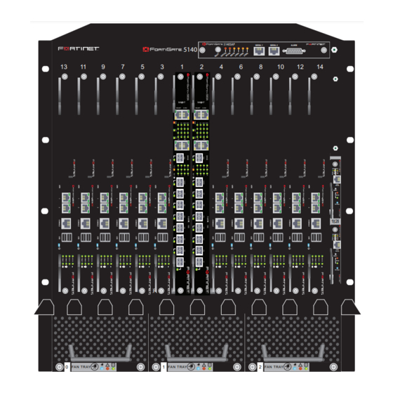
FortiGate-5140 chassis FortiGate-5140 chassis You can install up to 14 FortiGate-5000 series boards in the 14 front panel slots of the FortiGate-5140 ATCA chassis. The FortiGate-5140 is a 12U chassis that contains two redundant hot swappable DC power entry modules that connect to -48 VDC Data Center DC power. -
Page 20: Fortigate-5140 Chassis Back Panel
PEM B. Fortinet ships the FortiGate-5140 chassis with PEM A and PEM B installed. The PEMs provide redundant DC power connections for the FortiGate-5140 chassis and distribute DC power to the fan trays and to the FortiGate-5000 series boards installed in the FortiGate-5140 chassis. - Page 21 The back panel also includes the back cable tray, an ESD socket and the chassis ground connector. The ground connector must be connected to Data Center ground. Use the back cable tray for securing and managing DC power, RTN, and ground wires. FortiGate-5000 Series Introduction 01-30000-83466-20090108 http://docs.fortinet.com/ •...
-
Page 22: Physical Description Of The Fortigate-5140 Chassis
Temperature: 32 to 104°F (0 to 40°C) Relative humidity: 5 to 95% (Non-condensing) Temperature: -13 to 158 °F (-25 to 70°C) Relative humidity: 5 to 95% (Non-condensing) Maximum: 2,980W DC 2x redundant -48VDC to -58VDC FortiGate-5140 chassis FortiGate-5000 Series Introduction 01-30000-83466-20090108 http://docs.fortinet.com/ • Feedback... -
Page 23: Fortigate-5050-R Chassis
FortiGate-5050-R chassis FortiGate-5050-R chassis You can install up to five FortiGate-5000 series boards in the five slots of the FortiGate-5050 ATCA chassis. The FortiGate-5050 is a 5U 19-inch rackmount ATCA chassis that contains two redundant DC power connections that connect to -48 VDC Data Center DC power. -
Page 24: Fortigate-5050 Front Panel
Caution: Do not operate the FortiGate-5050 chassis with open slots on the front panel. For optimum cooling performance and safety, the slots must contain a FortiGate-5000 series board or an air baffle slot filler. As well the removable power supply panel must be installed over the power connectors on the back of the chassis. -
Page 25: Fortigate-5050 Back Panel
-48V to - 58V DC power input connectors labelled Input A and Input B. The power input connectors provide redundant DC power connections for the FortiGate-5050 chassis and distribute DC power to the fan tray and the FortiGate-5000 series boards installed in the FortiGate-5050 chassis. Each power input connector includes a 24 Amp circuit breaker that also functions as an on/off switch for the power input connector. -
Page 26: Physical Description Of The Fortigate-5050 Chassis
Temperature: 32 to 104°F (0 to 45°C) Relative humidity: 5 to 85% (Non-condensing) Temperature: -13 to 158 °F (-25 to 70°C) Relative humidity: 5 to 95% (Non-condensing) Maximum: 1,135 W 2x redundant -48VDC to -58VDC FortiGate-5050-R chassis FortiGate-5000 Series Introduction 01-30000-83466-20090108 http://docs.fortinet.com/ • Feedback... -
Page 27: Fortigate-5050 Chassis
FortiGate-5050 chassis FortiGate-5050 chassis You can install up to five FortiGate-5000 series boards in the five slots of the FortiGate-5050 ATCA chassis. The FortiGate-5050 is a 5U 19-inch rackmount ATCA chassis that contains two redundant DC power connections that connect to -48 VDC Data Center DC power. -
Page 28: Fortigate-5050 Front Panel
-48V to - 58V DC power input connectors labelled Input A and Input B. The power input connectors provide redundant DC power connections for the FortiGate-5050 chassis and distribute DC power to the fan tray and the FortiGate-5000 series boards installed in the FortiGate-5050 chassis. Each power input connector includes a 24 Amp circuit breaker that also functions as an on/off switch for the power input connector. -
Page 29: Physical Description Of The Fortigate-5050 Chassis
The back panel also contains 5 RTM slots numbered to correspond to the front panel slots. The RTM slots are available for FortiGate-5000 RTM modules such as the FortiGate-RTM-XB2 module. When the FortiGate-5050 chassis is shipped, these slots are covered by RTM slot filler panels. - Page 30 Physical description of the FortiGate-5050 chassis FortiGate-5050 chassis FortiGate-5000 Series Introduction 01-30000-83466-20090108 http://docs.fortinet.com/ • Feedback...
-
Page 31: Fortigate-5020 Chassis
FortiGate-5020 chassis FortiGate-5020 chassis You can install one or two FortiGate-5000 series boards in the two slots of the FortiGate-5020 ATCA chassis. The FortiGate-5020 is a 4U chassis that contains two redundant AC to DC power supplies that connect to AC power. The FortiGate-5020 chassis also includes an internal cooling fan tray. -
Page 32: Fortigate-5020 Back Panel
Relative humidity: 5 to 95% (Non-condensing) Storage environment Temperature: -20 to 80°C Relative humidity: 5 to 95% (Non-condensing) Power dissipation Maximum: 800 watts Power input 2x redundant 110 to 250 VAC FortiGate-5020 chassis Circuit breaker Power wire fixture FortiGate-5000 Series Introduction 01-30000-83466-20090108... -
Page 33: Fortigate-5001A Security System
Note: In most cases the base backplane interfaces are used for HA heartbeat communication and the fabric backplane interfaces are used for data communication. The FortiGate-5001A board also supports high-end FortiGate features including 802.1Q VLANs, multiple virtual domains, 802.3ad aggregate interfaces, and FortiOS Carrier. FortiGate-5000 Series Introduction 01-30000-83466-20090108... -
Page 34: Front Panel Leds And Connectors
Two fabric backplane interfaces (Fabric CH0 and Fabric CH1 on the front panel and fabric1 and fabric2 in the firmware) for HA heartbeat and data communications across the FortiGate-5000 chassis backplane. The fabric backplane interfaces operate at 1 Gbps. If you install a FortiGate-RTM-XB2 module the fabric backplane interfaces operate at 10 Gbps. -
Page 35: Leds
(Left LED) 1, 2 (Right LED) Base CH0 Base CH1 Fabric CH0 Fabric CH1 FortiGate-5000 Series Introduction 01-30000-83466-20090108 lists and describes the FortiGate-5001A LEDs. State Description Green The correct cable is connected to the interface and the connected equipment has power. -
Page 36: Connectors
The FortiGate-5001A fabric backplane interfaces can be used for data communication or HA heartbeat communication between FortiGate-5001A boards installed in the same or in different FortiGate-5000 chassis. To support 1-gigabit fabric backplane communications your FortiGate-5140 or FortiGate-5050 chassis must include one or more FortiSwitch-5003A boards or other 1-gigabit fabric backplane switching boards installed in the chassis in fabric slots 1 and 2. -
Page 37: Fortigate-Rtm-Xb2
Screw Handle The FortiGate-RTM-XB2 NP2 processors provide hardware accelerated network processing for eligible traffic passing through the FortiGate-RTM-XB2 interfaces. For information about Fortinet NP2 processor acceleration, see the Hardware Acceleration Technical Follow the instructions in the FortiGate-RTM-XB2 module. AMC modules You can install one FortiGate AMC Double width Module (ADM) in the FortiGate-5001A-DW front panel AMC double-width opening. - Page 38 Figure 15: FortiGate-ASM-FB4 LINK LINK LINK LINK ASM-FB4 Note: You can operate a FortiGate-5001A board with both a FortiGate-RTM-XB2 module and a supported FortiGate AMC module installed at the same time. FortiGate-5001A security system FortiGate-5000 Series Introduction 01-30000-83466-20090108...
-
Page 39: Fortigate-Rtm-Xb2 System
NP2 processors are connected by an Enhanced Extension Interface (EEI). The FortiGate-RTM-XB2 can accelerate eligible traffic that enters and exits the same FortiGate-RTM-XB2 interface or that enters one FortiGate-RTM-XB2 interface and exits the other. For more information about Fortinet NP2 processor acceleration, see the Figure 16: FortiGate-RTM-XB2 front panel... -
Page 40: Front Panel Led
3 provides two 10-gigabit fabric channels and NP2 acceleration for the FortiGate-5001A board FortiGate-5001A Board Installed in FortiGate-5050 front panel slot 3 Fabric Channel 2 10-gigabit Data POWER Communication 5000SM 10/100 SERIAL link/Act 10/100 link/Act External Network FortiGate-5000 Series Introduction 01-30000-83466-20090108... -
Page 41: Fortigate-5005Fa2 Security System
Two fabric backplane gigabit interfaces (fabric1 and fabric2) for FortiGate-5005-DIST security system management communications. The fabric backplane gigabit interfaces can also be used for data communications across the FortiGate-5000 chassis backplane if combined with a board that supports backplane fabric switching. •... -
Page 42: Front Panel Leds And Connectors
The front panel also includes the RJ-45 console port for connecting to the FortiOS CLI and two USB ports. The USB ports can be used with a Fortinet USB key. For information about using the FortiUSB key, see the Series Firmware and FortiUSB Guide. -
Page 43: Connectors
Packet size does not affect performance for traffic with long session lifetime. For long sessions, processing that would otherwise be handled by the FortiGate-5005FA2 CPUs is off-loaded to the acceleration module. FortiGate-5000 Series Introduction 01-30000-83466-20090108 Accelerated packet forwarding and policy enforcement... -
Page 44: Fa2 Interfaces And Active-Active Ha Performance
The FortiGate-5005FA2 base1 and base2 backplane gigabit interfaces can be used for HA heartbeat communication between FortiGate-5005FA2 boards installed in the same or in different FortiGate-5000 chassis. You can also configure FortiGate-5005FA2 boards to use the base backplane interfaces for data communication between FortiGate boards. -
Page 45: Fortigate-5001Fa2-Lenc Security System
Use the front panel interfaces for connections to your networks and the backplane interfaces for communication between FortiGate-5000 series boards over the FortiGate-5000 chassis backplane. You can also configure two or more FortiGate-5001FA2-LENC boards to create a... -
Page 46: Front Panel Leds And Connectors
The front panel also includes the RS-232 console port for connecting to the FortiOS CLI and a USB port. The USB port can be used with a Fortinet USB key. For information about using the FortiUSB key, see the Firmware and FortiUSB Guide. -
Page 47: Connectors
For long sessions, processing that would otherwise be handled by the FortiGate-5001FA2-LENC CPUs is off-loaded to the acceleration module. • Firewall and intrusion protection (IPS), when there is a reasonable percentage of P2P packets. FortiGate-5000 Series Introduction 01-30000-83466-20090108 Accelerated packet forwarding and policy enforcement State Description... -
Page 48: Fa2 Interfaces And Active-Active Ha Performance
The FortiGate-5001FA2-LENC port9 and port10 base backplane gigabit interfaces can be used for HA heartbeat communication between FortiGate-5001FA2-LENC boards installed in the same or in different FortiGate-5000 chassis. You can also configure FortiGate-5001FA2-LENC boards to use the base backplane interfaces for data communication between FortiGate boards. -
Page 49: Fortigate-5001Sx Security System
Use the front panel interfaces for connections to your networks and the backplane interfaces for communication between FortiGate-5000 series boards over the FortiGate-5000 chassis backplane. You can also configure two or more FortiGate-5001SX boards to create a high... -
Page 50: Front Panel Leds And Connectors
The front panel also includes the RS-232 console port for connecting to the FortiOS CLI and a USB port. The USB port can be used with a Fortinet USB key. For information about using the FortiUSB key, see the Firmware and FortiUSB Guide. -
Page 51: Connectors
The FortiGate-5001SX port9 and port10 base backplane gigabit interfaces can be used for HA heartbeat communication between FortiGate-5001SX boards installed in the same or in different FortiGate-5000 chassis. You can also configure FortiGate-5001SX boards to use the base backplane interfaces for data communication between FortiGate boards. - Page 52 Base backplane gigabit interfaces FortiGate-5001SX security system FortiGate-5000 Series Introduction 01-30000-83466-20090108...
-
Page 53: Fortiswitch-5003A System
2 provides communications on fabric channel 2 and base channel 2. If your chassis includes one FortiSwitch-5003A board you can install it in hub/switch fabric slot 1 or 2 and configure the FortiGate-5000 boards installed in the chassis to use the correct fabric and base backplane interfaces. -
Page 54: Front Panel Leds And Connectors
RJ-45 RS-232 console port for connecting to the FortiSwitch-5003A CLI. FortiSwitch-5003A system 14/F8 F7 F6 F5 F4 F3 F2 F1 Fabric 10G Optical or Copper SFP Hot Swap Extraction Reset Switch FortiGate-5000 Series Introduction 01-30000-83466-20090108 Retention Screw Lever... -
Page 55: Leds
Press and hold Reset for three seconds to restart the FortiSwitch-5003A board. Solid Indicates this interface is connected to the 1-gigabit Green base channel interface of a FortiGate-5000 board. Table 17 on page 56 LEDs and the interface that each represents. Blinking Indicates 1-gigabit network traffic on this interface. -
Page 56: Base Channel Interfaces
LED will be lit if any board is installed in the second hub/switch fabric slot, including a FortiSwitch-5003A board or any FortiGate-5000 board. 3 to 14 Base channel connection to FortiGate-5000 boards in chassis slots 3 to FortiSwitch-5003A system FortiGate-5000 Series Introduction 01-30000-83466-20090108... -
Page 57: Fabric Channel Interfaces
FortiSwitch-5003A CLI. The fabric network activity LEDs show links and network activity for the interfaces and connections listed in Figure 23: FortiSwitch-5003A fabric network activity LEDs FortiGate-5000 Series Introduction 01-30000-83466-20090108 Description Front panel gigabit base channel interfaces B1 and B2. -
Page 58: Front Panel Connectors
F7, F6, F5, F4, F3, F2, You can operate the FortiSwitch-5003A board as a fabric and base channel layer-2 switch for any FortiGate-5000 board. The FortiSwitch-5003A board is compatible with all FortiGate-5000 boards. Figure 24 shows a FortiGate-5050 chassis with a FortiSwitch-5003A board in slot 1 and two FortiGate-5001A boards in slots 3 and 4. -
Page 59: Fabric 10-Gigabit Switching Within A Chassis
FortiGate-5001A board. Using these components this chassis supplies 10-gigabit connectivity between the external and internal network. Figure 25: Example 10-gigabit connection between internal and external networks Fabric Channel 1 10 Gigabit Data Communication FortiGate-5000 Series Introduction 01-30000-83466-20090108 5000SM 5050SAP 10/100 link/Act... -
Page 60: Layer-2 Link Aggregation And Redundancy Configurations
6, 8, 9, 10, 11, and 13 to provide 10-gigabit ETH0 ETH1 fabric interfaces and ETH0 Service NP2 acceleration for each RESET STATUS FortiGate-5001A board Hot Swap ETH0 ETH1 ETH0 Service RESET STATUS Hot Swap FA N TR AY FortiGate-5000 Series Introduction 01-30000-83466-20090108... -
Page 61: Fortiswitch-5003 System
2. If your configuration includes only one FortiSwitch-5003 board you can install it in slot 1 or slot 2 and configure the FortiGate-5000 boards installed in the chassis to use the correct base backplane interface. The FortiSwitch-5003 board includes the following features: •... -
Page 62: Leds
LED indicates the speed of the link. Flashing Initialization completed successfully. Green Green Initialization completed successfully. FortiSwitch-5003 system ZRE Network LED Mode Switch Activity LEDs Reset (ZRE 0 to 15) Switch Extraction Swap Lever Mounting Knot lists the ZRE LEDs and the FortiGate-5000 Series Introduction 01-30000-83466-20090108... -
Page 63: About The Zre Network Activity Leds
ZRE0 front panel interface. ZRE1 front panel interface. ZRE2 front panel interface. Base backplane connection to FortiGate-5000 series boards in chassis slots 3 to 14. Base backplane link. Indicates that the FortiSwitch-5003 board can connect to the base backplane interface. -
Page 64: Connectors
FortiSwitch-5003 boards installed in a FortiGate-5140 or FortiGate-5050 chassis in slot 1 or slot 2 provide base backplane switching for all of the FortiGate-5000 series boards installed in chassis slots 3 and above. Base backplane switching can be used for HA heartbeat communication and for data communication between FortiGate-5000 series boards. - Page 65 If you have two FortiSwitch-5003 boards and two backplane interfaces available you can balance the traffic between the base backplane interfaces by how you configure your FortiGate-5000 board data interfaces and HA heartbeat interfaces. For example, if you have two busy FortiGate-5001SX clusters you might configure one cluster to use port9 for HA heartbeat traffic and the other to use port10.
- Page 66 Base backplane communications FortiSwitch-5003 system FortiGate-5000 Series Introduction 01-30000-83466-20090108...
-
Page 67: The Fortigate-5005-Dist Security System
Internet and a private network. In this configuration, the FortiGate-5005-DIST security system can provide FortiGate services to 10 gigabit traffic passing between the private network and the Internet. FortiGate-5000 Series Introduction 01-30000-83466-20090108 Figure 29 on page 68). This system can be installed in NAT/Route... -
Page 68: Forticontroller-5208 I/O Boards
COM 1 COM 2 Management D15/D16 C15/C16 interface (mng) 5000SM 10/100 link/Act SERIAL 10/100 link/Act SFP Gigabit Fiber or Copper Management RJ-45 Serial MANAGEMENT COM 1 COM 2 D15/D16 C15/C16 Mounting Extraction Lever Management RJ-45 Ethernet FortiGate-5000 Series Introduction 01-30000-83466-20090108 Knot... -
Page 69: Fortigate-5005Fa2 Worker Boards
IPS and routing to distributed traffic. Figure 31: FortiGate-5005FA2 front panel Fabric and Base network activity Mounting Knot Extraction FortiGate-5000 Series Introduction 01-30000-83466-20090108 1 2 3 4 5 6 SPF Gigabit LEDs Fiber or Copper LINK LINK CONSOLE... -
Page 70: Fortigate-5005-Dist Security System Chassis
The FortiGate-5005-DIST security system FortiGate-5140 5140SAP SERIAL 1 SERIAL 2 ALARM FABRIC FABRIC FABRIC BASE BASE BASE ETH0 ETH1 ETH0 Service RESET STATUS Hot Swap ETH0 ETH1 ETH0 Service RESET STATUS Hot Swap FA N TR AY FortiGate-5000 Series Introduction 01-30000-83466-20090108... -
Page 71: Fortigate-5050 Chassis
<I/O_board_interface_name> is the name of the interface as shown on the FortiController-5208 front panel. Table 24 on page 72 and secondary board front panel interfaces and the interface names that appear on the FortiGate-5005-DIST worker web-based manager and CLI. FortiGate-5000 Series Introduction 01-30000-83466-20090108 FortiGate-5050 Chassis LINK LINK... - Page 72 1 Management Secondary FortiController-5208 board installed in chassis slot 2 Management The FortiGate-5005-DIST security system Web-based manager and CLI interface names port1_X1 port1_X2 port1_1 port1_2 port1_3 port1_4 port2_X1 port2_X2 port2_1 port2_2 port2_3 port2_4 Not used. FortiGate-5000 Series Introduction 01-30000-83466-20090108...
-
Page 73: Forticontroller-5208 System
XFP or SFP transceivers into the FortiController-5208 front panel cage slots. This chapter includes the following information about the FortiController-5208 board: • Front panel LEDs and connectors • Backplane gigabit interfaces • Installing XFP and SFP transceivers FortiGate-5000 Series Introduction 01-30000-83466-20090108... -
Page 74: Front Panel Leds And Connectors
LED 2 will always be off, even if an operating FortiController-5208 is in slot 2. FortiController-5208 system SFP Gigabit Fiber or Copper Management RJ-45 Serial MANAGEMENT COM 1 COM 2 D15/D16 C15/C16 Mounting Extraction Lever Management RJ-45 Ethernet FortiGate-5000 Series Introduction 01-30000-83466-20090108 Knot... -
Page 75: Connectors
LEDs of each FortiController-5208 board will indicate only its own communication. Connectors Table 26 Table 26: FortiController-5208 connectors Connector X1, X2 FortiGate-5000 Series Introduction 01-30000-83466-20090108 State Description 1-16 Green The control LEDs display the fabric backplane... -
Page 76: Backplane Gigabit Interfaces
Two 1 gigabit SFP interfaces used for inter-chassis high-availability (HA) connections. For future use. RS-232 Serial connection to the command line serial interface. Ethernet management connection to the FortiController-5208 web-based manager and command line interface. FortiGate-5000 Series Introduction 01-30000-83466-20090108... - Page 77 www.fortinet.com...