Fortinet FortiGate FortiGate-5000 Quick Manual
Fortigate-5000 series
Hide thumbs
Also See for FortiGate FortiGate-5000:
- Introduction manual (77 pages) ,
- Backplane communications manual (47 pages) ,
- Firmware and fortiusb manual (23 pages)
Table of Contents
Advertisement
Quick Links
Download this manual
See also:
Administration Manual
13
11
9
7
A high-level guide to all three FortiGate-5000 series chassis and the FortiGate and FortiSwitch modules that you can
install in them. For detailed information about the FortiGate-5000 series hardware, see the
Hardware Guide
and the
5
3
1
2
4
6
8
10
MANAGEMENT
MANAGEMENT
E
E
T
T
H
H
O
O
SYSTEM
SYSTEM
CONSOLE
CONSOLE
R
R
S
S
2
2
3
3
2
2
Z
Z
R
R
E
E
0
0
Z
Z
R
R
E
E
1
1
Z
Z
R
R
E
E
2
2
E2
E1
E2
E1
14
15
14
15
12
13
12
13
10
11
10
11
8
9
8
9
6
7
6
7
4
5
4
5
2
3
2
3
0
1
0
1
ZRE
ZRE
CLK
OK
CLK
OK
EXT
INT
EXT
INT
FLT
FLT
FLT
FLT
HOT SWAP
HOT SWAP
RESET
RESET
LED MODE
LED MODE
FortiGate-5000 Installation
Q U I C K G U I D E
FortiGate-5000 Series
5140
12
14
5
PWR ACC
Crit.
4
Maj.
Min.
PWR ACC
3
2
1
3
PWR ACC
Rst
2
1
Link
Act
100
ShMC
2
ETH 0
Prim.
ShMC
Stat.
Link
Act
100
ETH 0
Sec.
ShMC
Stat.
RESET
RESET
Guide.
www.fortinet.com
USB
1
2
3
4
5
6
7
CONSOLE
USB
CONSOLE
1
2
3
4
5
6
7
USB
CONSOLE
1
2
3
4
5
6
7
Critical
Major
Minor
Alarm
Alarm
Reset
USB
CONSOLE
1
6
2
5
3
4
5
6
STATUS
PWR
IPM
USB
CONSOLE
1
6
2
3
5
4
5
6
STATUS
PWR
IPM
FortiGate-5000 Series
8
STA IPM
8
STA IPM
8
STA IPM
POWER
ShMC
Hot Swap
Status
1
Console
Ethernet
PSU A
PSU B
ALT
ON/OFF
ALT
ON/OFF
Advertisement
Table of Contents

Related Manuals for Fortinet FortiGate FortiGate-5000


Summary of Contents for Fortinet FortiGate FortiGate-5000
- Page 1 CONSOLE Link ShMC ETH 0 Prim. ShMC Stat. Link HOT SWAP RESET ETH 0 LED MODE Sec. ShMC Stat. Guide. www.fortinet.com CONSOLE PWR ACC CONSOLE PWR ACC CONSOLE PWR ACC Critical Major Minor Alarm Alarm Console Reset CONSOLE RESET STATUS...
- Page 2 FortiGate-5000 Series Quick Guide 15 March 2006 01-00000-0294-20060315 © Copyright 2006 Fortinet, Inc. All rights reserved. No part of this publication including text, examples, diagrams or illustrations may be reproduced, transmitted, or translated in any form or by any means, electronic, mechanical, manual, optical or otherwise, for any purpose, without prior written permission of Fortinet, Inc.
-
Page 3: Table Of Contents
Contents Contents Introduction ... 5 FortiGate-5140 chassis... 7 FortiGate-5050 chassis... 13 FortiGate-5020 chassis... 19 FortiGate-5001SX security system ... 21 FortiGate-5001FA2 security system ... 25 FortiGate-5002FB2 security system ... 29 FortiSwitch-5003 module... 33 FortiGate-5000 Series Quick Guide 01-00000-0294-20060315... - Page 4 Contents FortiGate-5000 Series Quick Guide 01-00000-0294-20060315...
-
Page 5: Introduction
Fortinet Knowledge Center Additional Fortinet technical documentation is available from the Fortinet Knowledge Center. The knowledge center contains troubleshooting and how-to articles, FAQs, technical notes, and more. Visit the Fortinet Knowledge Center at http://kc.forticare.com. Customer service and technical support Fortinet Technical Support provides services designed to make sure that your Fortinet systems install quickly, configure easily, and operate reliably in your network. - Page 6 Customer service and technical support Introduction FortiGate-5000 Series Quick Guide 01-00000-0294-20060315...
-
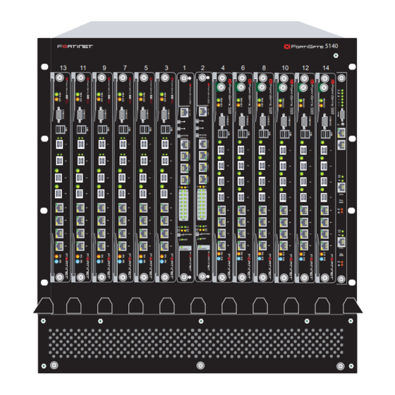
Page 7: Fortigate-5140 Chassis
FortiGate-5140 chassis FortiGate-5140 chassis You can install up to 14 FortiGate-5000 series modules in the 14 slots of the FortiGate-5140 ATCA chassis. The FortiGate-5140 is a 12U chassis that contains two redundant hot swappable DC power entry modules that connect to -48 VDC Data Center DC power. - Page 8 Figure 2 shows the back panel of the FortiGate-5140 chassis. The back panel includes two hot-swappable redundant -48V/-60 VDC power entry modules (PEMs) labelled PEM A and PEM B. Figure 2: FortiGate-5140 chassis back panel Back cable tray -48V -48V -48V/-60 VDC nom Ground connectors...
- Page 9 Data Center ground Connect the FortiGate-5140 chassis to Data Center DC power (also called battery power) using the redundant power entry modules (PEMs). Fortinet supplies and recommends AWG-14 stranded wires for all power connections. Black for -48VDC, red for RTN, and green for ground. If required, install terminal lugs on the wires before connecting them to the PEM terminal strips.
- Page 10 Connecting the FortiGate-5140 chassis to AC power using the FortiGate-5053 power converter tray Connecting the FortiGate-5140 chassis to AC power using the FortiGate-5053 power converter tray Selecting the power supplies and power convertor trays that you need for your FortiGate-5140 configuration If Data Center DC power is not available, you can use the FortiGate-5053 power converter tray with FortiGate-5140 power supplies (shown in AC power to DC power.
- Page 11 FortiGate-5140 chassis Connecting the FortiGate-5140 chassis to AC power using the FortiGate-5053 power converter tray Basic power requirements To supply enough power for a FortiGate-5140 chassis with a total of 14 FortiGate and FortiSwitch modules you require one FortiGate-5053 power converter tray and two FortiGate-5140 power supplies (see supplies are installed in FortiGate-5053 slots 1 and 2.
- Page 12 Connecting the FortiGate-5140 chassis to AC power using the FortiGate-5053 power converter tray Connecting a FortiGate-5140 chassis to the FortiGate-5053 power converter tray To use a FortiGate-5053 power converter tray with the FortiGate-5140 chassis you need to make DC power connections between the FortiGate-5140 chassis and the FortiGate-5053 power converter tray.
-
Page 13: Fortigate-5050 Chassis
FortiGate-5050 chassis FortiGate-5050 chassis You can install up to five FortiGate-5000 series modules in the five slots of the FortiGate-5050 ATCA chassis. The FortiGate-5050 is a 5U chassis that contains two redundant DC power connections that connect to -48 VDC Data Center DC power. - Page 14 Input A Connect the FortiGate-5050 chassis to Data Center DC power (also called battery power) using the redundant power input connectors. Fortinet supplies and recommends AWG-14 stranded wires for all power connections. Black for -48VDC, red for RTN, and green for ground. If required, install terminal lugs on the wires before connecting them to the power input connectors.
- Page 15 FortiGate-5050 chassis Connecting the FortiGate-5050 chassis to AC power using the FortiGate-5053 power converter tray Figure 12: Connecting a FortiGate-5050 chassis to Data Center ground Data Center ground connector Connecting the FortiGate-5050 chassis to AC power using the FortiGate-5053 power converter tray If Data Center DC power is not available, you can use the FortiGate-5053 power converter tray with FortiGate-5020/5050 power supplies (shown in convert AC power to DC power.
- Page 16 Connecting the FortiGate-5050 chassis to AC power using the FortiGate-5053 power converter tray Selecting the power supplies and power convertor trays that you need for your FortiGate-5050 configuration The FortiGate-5053 power converter tray contains space for up to three FortiGate-5020/5050 power supplies. A FortiGate-5020/5050 power supply converts AC power to -48 VDC power.
- Page 17 FortiGate-5050 chassis Connecting the FortiGate-5050 chassis to AC power using the FortiGate-5053 power converter tray Connecting a FortiGate-5050 chassis to the FortiGate-5053 power converter tray To use a FortiGate-5053 power converter tray with the FortiGate-5050 chassis you need to make DC power connections between the FortiGate-5050 chassis and the FortiGate-5053 power converter tray.
- Page 18 Connecting the FortiGate-5050 chassis to AC power using the FortiGate-5053 power converter tray FortiGate-5050 chassis FortiGate-5000 Series Quick Guide 01-00000-0294-20060315...
-
Page 19: Fortigate-5020 Chassis
FortiGate-5020 chassis FortiGate-5020 chassis You can install one or two FortiGate-5000 series modules in the two slots of the FortiGate-5020 ATCA chassis. The FortiGate-5020 is a 4U chassis that contains two redundant AC to DC power supplies that connect to AC power. The FortiGate-5020 chassis also includes an internal cooling fan tray. - Page 20 Connecting the FortiGate-5020 chassis to AC power Connecting the FortiGate-5020 chassis to AC power Figure 18: FortiGate-5020 chassis back panel AC power connector Hot swappable Power cooling fan tray wire fixture The AC power connectors on the back of the FortiGate-5020 chassis provide power to two factory installed redundant FortiGate-5020/5050 power supplies.
-
Page 21: Fortigate-5001Sx Security System
FortiGate-5001SX security system FortiGate-5001SX security system The FortiGate-5001SX security system module is a high-performance FortiGate security system with a total of 8 Gigabit ethernet interfaces. The FortiGate-5001SX module supports high-end features including 802.1Q VLANs and multiple virtual domains. You can also configure two or more FortiGate-5001SX modules to create a high availability (HA) cluster to provide failover protection and load balancing. -
Page 22: Changing Jumper Settings
Ethernet CONSOLE DB-9 9600 bps RS-232 serial Serial connection to the command line The JP3 jumper on the FortiGate-5001SX module is factory set by Fortinet into one of two positions (see Figure 20 on page • For a FortiGate-5140 or FortiGate-5050 chassis, the jumper connects pins 2 and 3 •... - Page 23 FortiGate-5001SX security system Normally, because the jumpers are factory set, you do not have to change them. However, if you are moving a FortiGate-5001SX from a FortiGate-5140 or FortiGate-5050 to a FortiGate-5020 or the reverse, you need to move the JP3 jumper.
- Page 24 Inserting a FortiGate-5001SX module into a chassis Figure 21: FortiGate-5001SX module mounting components Closed Alignment Pin Mounting Knot Locking Left Extraction Screw Lever Table 4: FortiGate-5001SX normal operating LEDs State Green Off (Or flashing red when the system accesses the FortiGate-5001SX flash disk.) Green FortiGate-5001SX security system...
-
Page 25: Fortigate-5001Fa2 Security System
FortiGate-5001FA2 security system FortiGate-5001FA2 security system The FortiGate-5001FA2 security system module is a high-performance FortiGate security system similar to the FortiGate-5001SX security system but with added accelerated packet forwarding and policy enforcement for two of its eight Gigabit ethernet interfaces. Accelerated packet forwarding and policy enforcement results in accelerated small packet performance required for voice, video, and other multimedia streaming applications. - Page 26 CONSOLE DB-9 9600 bps RS-232 serial The JP3 jumper on the FortiGate-5001FA2 module is factory set by Fortinet into one of two positions (see Figure 23 on page • For a FortiGate-5140 or FortiGate-5050 chassis, the jumper connects pins 2 and 3 •...
- Page 27 FortiGate-5001FA2 security system Normally, because the jumpers are factory set, you do not have to change them. However, if you are moving a FortiGate-5001FA2 from a FortiGate-5140 or FortiGate-5050 to a FortiGate-5020 or the reverse, you need to move the JP3 jumper.
- Page 28 Inserting a FortiGate-5001FA2 module into a chassis Inserting a FortiGate-5001FA2 module into a chassis The FortiGate-5001FA2 module left extraction lever contacts to a hidden power switch. The module must be fully installed in a chassis slot and this extraction lever must be closed and locked for the FortiGate-5001FA2 module to receive power and operate normally.
-
Page 29: Fortigate-5002Fb2 Security System
FortiGate-5002FB2 security system FortiGate-5002FB2 security system The FortiGate-5002FB2 security system module is a high-performance FortiGate security system with accelerated packet forwarding and policy enforcement for two of its six Gigabit ethernet interfaces. Accelerated packet forwarding and policy enforcement results in accelerated small packet performance required for voice, video, and other multimedia streaming applications. - Page 30 Table 9: FortiGate-5002FB2 module LEDs State Description STATUS Green Normal operation. The FortiGate-5002FB2 is booting or a fault condition exists. Green The FortiGate-5002FB2 module is powered on. Blue The FortiGate-5002FB2 is ready to be hot-swapped (or card is ready to be removed from the chassis). Flashing The FortiGate-5002FB2 is changing from hot swap to running Blue...
- Page 31 FortiGate-5002FB2 security system Inserting a FortiGate-5002FB2 module into a chassis The FortiGate-5002FB2 module left extraction lever contacts to a hidden power switch. The module must be fully installed in a chassis slot and this extraction lever must be closed and locked for the FortiGate-5002FB2 module to receive power and operate normally.
- Page 32 Inserting a FortiGate-5002FB2 module into a chassis FortiGate-5002FB2 security system FortiGate-5000 Series Quick Guide 01-00000-0294-20060315...
-
Page 33: Fortiswitch-5003 Module
FortiSwitch-5003 module FortiSwitch-5003 module The FortiSwitch-5003 module provides switching for the FortiGate-5140 chassis and the FortiGate-5050 chassis. This switching takes the form of backplane HA heartbeat connections between FortiGate-5000 series modules installed in a FortiGate-5140 chassis or a FortiGate-5050 chassis. You can install a second FortiSwitch-5003 module in a FortiGate-5140 or FortiGate-5050 chassis as a backup or redundant switch. - Page 34 Table 12: FortiSwitch-5003 module LEDs (Continued) State Description Yellow Link/Activity mode - Port is not forwarding packets. Link/Speed mode - Indicates 1000 Mbps connection Network activity Green Link/Activity mode - Blinking LED indicates network traffic. LEDs Link/Speed mode - Indicates 100 Mbps connection. 0-15 Link/Activity mode - No link.
- Page 35 FortiSwitch-5003 module Inserting a FortiSwitch-5003 module into a chassis The FortiSwitch-5003 module left extraction lever contacts to a hidden power switch. The module must be fully installed in a chassis slot and this extraction lever must be closed and locked for the FortiSwitch-5003 module to receive power and operate normally.
- Page 36 Inserting a FortiSwitch-5003 module into a chassis FortiSwitch-5003 module FortiGate-5000 Series Quick Guide 01-00000-0294-20060315...
- Page 37 www.fortinet.com...