Table of Contents
Advertisement
Quick Links
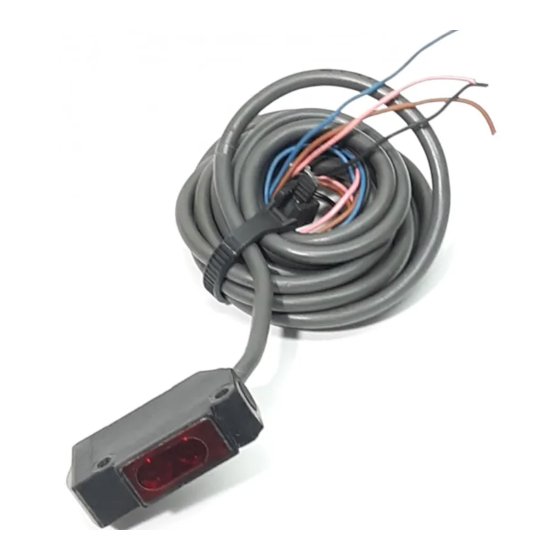
Built-in Amplifier Photoelectric Sensor
Easy-to-use, Low-cost Photoelectric
Sensor
Incorporating indicators that can be
clearly seen from a distance
Conforms to EN and IEC standards
Incorporating polarizing function, thus
accurately detecting lustrous objects
Resin-filled construction resists vibration
and ensures IP67 water-resistance
Replaces E3V sensor
Ordering Information
Connection
Appearance
Method
Cord connection
Cord length: 2 m Through-beam
g
Note:
Mounting brackets are not provided with the E3V3. Order them separately.
ACCESSORIES (ORDER SEPARATELY)
Attachments
Name
Retroreflector
Retroreflector (tape type)
Slit for Through-beam Sensor
Sensing Method
g
Detection
Distance
7 m (23 ft)
Retroreflective
2 m (6.6 ft)
(polarized)
Diffuse reflective
0.5 to 8 cm
(0.20 to 3.15 in)
70 cm (2.3 ft)
Remarks
Corner cube reflector
Glass bead adhesive back
0.5, 1, 2 dia. slits
E3V3
Operating Mode
Output
NPN
Light-ON
g
E3V3-T61
Dark-ON
E3V3-R61
(selectable by
wiring)
wiring)
E3V3-D61
E3V3-D62
Part Number
E39-R3
E39-RSA, E39-RSB
E39-S7
PNP
E3V3-T81
E3V3-R81
E3V3-D81
E3V3-D82
Advertisement
Table of Contents

Related Manuals for Omron E3V3


Summary of Contents for Omron E3V3
- Page 1 0.5 to 8 cm E3V3-D61 E3V3-D81 (0.20 to 3.15 in) 70 cm (2.3 ft) E3V3-D62 E3V3-D82 Note: Mounting brackets are not provided with the E3V3. Order them separately. ACCESSORIES (ORDER SEPARATELY) Attachments Name Remarks Part Number Retroreflector Corner cube reflector...
-
Page 2: Application Examples
E3V3 E3V3 Mounting Brackets Part Number Remarks E39-L104 Standard vertical-mounting bracket E39-L44 Rear-mounting bracket E39-L43 Side-mounting bracket E39-L98 Metal cover E39-L93 Sensor adjustor E39-L104 E39-L44 E39-L43 E39-L98 E39-L93 Application Examples Detection of Cardboard Boxes Detection of Labels Detection of Automobiles at Indoor... -
Page 3: Specifications
E3V3 E3V3 Specifications Sensing Method Through-beam Retroreflective Diffuse Reflective (with MSR function) NPN output E3V3-T61 E3V3-R61 E3V3-D61 E3V3-D62 PNP output E3V3-T81 E3V3-R81 E3V3-D81 E3V3-D82 LED light source Infrared LED Red LED Infrared LED Sensitivity adjustment Adjustor Connection method Drawing cord-Standard length: 2 m (6.6 ft) Weight Approx. -
Page 4: Engineering Data
E3V3 E3V3 Retroreflector Specifications Item E39-R3 E39-RSA E39-RSB Detection distance (with E3V3) 5 to 100 cm 20 to 50 cm 20 to 80 cm Directional angle 30° min. Ambient Operating --25°C to 55°C (--13°F to 131°F) temperature Storage --40°C to 70°C (--40°F to 158°F) -
Page 5: Operation
E3V3 E3V3 EXCESS GAIN VS. SET DISTANCE (TYPICAL) E3V3-T E3V3-R E3V3-D Operating level Operating level Operating level Distance (m) Distance (m) Distance (cm) E3V3-D Operating level Distance (cm) Operation OUTPUT CIRCUITS Output Mode Connection Output Circuits Configuration Switch Method Light-ON... -
Page 6: Timing Charts
(see circuit max. Blue (relay) note) Pink Operating selection Note: The E3V3 Model with a junction connector has a white cord instead of a pink cord. Emitter (NPN/PNP) Brown Emitter indicator Connector Pin Arrangement (orange) 12 to Main... - Page 7 A and C, where the turn the sensitivity adjustor E3V3 detects the background object and best sensitivity of the E3V3 for the clockwise to increase the sensitivity the orange operation indicator is lit. The sensing object is ensured, and make...
- Page 8 4 dia. (16 x 0.12 dia.); standard length: 2 m (1.00) (0.67) Brown: Vcc Blue: Black: Output Pink: Mode selection (0.12) Two, M3 (0.28) Note: 18.4 (0.72) for E3V3-D61/-D81. (0.71) E3V3-R 11.3 Operation indicator (0.44) Stability indicator (0.16) 10.4 (0.41) 3.95 Sensitivity (0.16)
- Page 9 E3V3 E3V3 ATTACHMENT 40.3 (1.59) E39-R1 Retroreflector (0.30) (1.34) Two, 3.5 dia Provided with the (0.28) E3V3-R61/-R81 59.9 (2.36) (2.05) (0.06) (0.31) (0.11) ACCESSORIES (ORDER SEPARATELY) E39-R3 Retroreflector With Mounting Bracket (1.14) (Small Type) (Sold Together) (0.18) ° 13.7 14 Adhesive tape (0.43)
- Page 10 E39-L98 With Mounting Bracket ° ° (E3V3-D62) Two, R28 58 dia. 58 dia. (1.73) Four, R3.3 Two, R22 (0.12) (0.71) 10.4 Two, M3 (For E3V3) 25.4 25.4 (1.00) (2.40) (1.00) (0.79) (0.63) (2.40) 36.6 Optical (1.44) axis (1.89) (0.98) (2.20) (1.34)
- Page 11 Note: 1. A: 0.5, 1, or 2 dia. 18.9 (0.74) 2. Attach an E39-S7 Slit to both the emission panel of the emitter and the receiver’s sensing panel of the E3V3-T (0.36) Detection Distance (Rating) Item Diameter 0.5 dia. 1 dia.
- Page 12 MOUNTING The permissible voltage imposed on the E3V3 must be 24 VDC + When mounting the E3V3, do not hit the E3V3 with a hammer, or the 10% maximum (i.e., 26.4 V). Make sure that the voltage imposed on E3V3 will loose watertightness.