Table of Contents
Advertisement
Quick Links
Advertisement
Table of Contents

Related Manuals for UNI-T UT219P


Summary of Contents for UNI-T UT219P
- Page 1 P/N:110401111507X UT219P AC Digital Power Clamp Meter User Manual...
- Page 2 Preface Thank you for purchasing this brand new product. In order to use this product safely and correctly, please read this manual thoroughly, especially the safety notes. After reading this manual, it is recommended to keep the manual at an easily accessible place, preferably close to the device, for future reference.
-
Page 3: Table Of Contents
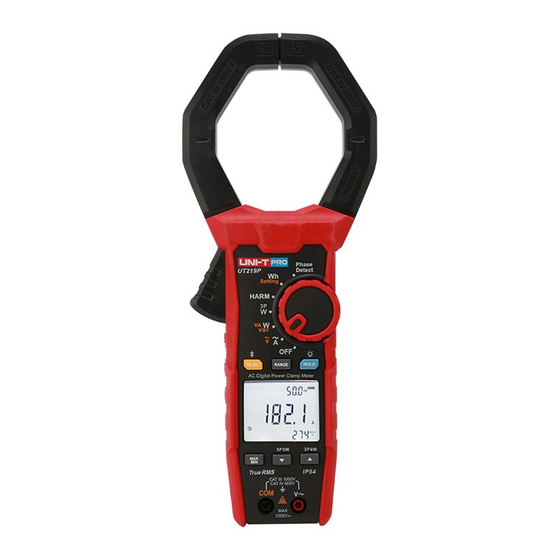
UT219P User Manual I. Overview UT219P is a digital power clamp with fundamental frequency up to 1 kHz. This clamp meter can be used to measure AC voltage, AC current, active power, apparent power, reactive power, power factor, phase angle, power quality, frequency, phase sequence, total harmonic distortion, harmonic component, etc. -
Page 4: Accessories
UT219P User Manual UT219P User Manual V. Electrical Symbols III. Accessories Check the accessories in the package, if any of them is missing or damaged, please contact System Description your supplier immediately. Application around and removal from UNINSULATED HAZARDOUS LIVE... -
Page 5: External Structure And Test Leads
UT219P User Manual UT219P User Manual VIII. LCD Display (Fig. 2) VII. External Structure and Test Leads (Fig. 1) Fig. 2 : Bluetooth communication symbol 2) RANGE: MANUAL: Manual current measurement mode 3) PF: Power factor 4) 3P3W: 3-phase 3-wire measurement mode... -
Page 6: Rotary Switch
UT219P User Manual UT219P User Manual 2. MAX/MIN IX. Rotary Switch (Fig. 3) Phase → → Short press this button to cyclically select real-time value maximum value minimum Detect → value average value on the main display, and to record the time of capturing maximum and minimum values. - Page 7 UT219P User Manual UT219P User Manual 1) Connect red test lead (connected with red alligator clip already) with “V” terminal; and black 1. AC current measurement (Fig. 4) (connected with black alligator clip already) with “COM”. 2) Set the rotary switch to “A~/V~”, press SELECT to select AC voltage measurement, and connect the alligator clips with power source or load to be measured in parallel.
- Page 8 UT219P User Manual UT219P User Manual 1) Connect red test lead (connected with red alligator clip already) with “V” terminal; and black if the measured conductor is not placed at the center of the clamp jaws. The clamp can only measure a current conductor at a time, if it measures two or more current conductors at the (connected with black alligator clip already) with “COM”.
- Page 9 UT219P User Manual UT219P User Manual 1) Connect red test lead (connected with red alligator clip already) with “V” terminal; and black 1) Connect red test lead (connected with red alligator clip already) with “V” terminal; and (connected with black alligator clip already) with “COM”.
- Page 10 UT219P User Manual UT219P User Manual 1) Connect red test lead (connected with red alligator clip already) with “V” terminal; and 5) According to the wire connection interface (Fig. 10), clamp L3 live wire, connect L3 live wire black (connected with black alligator clip already) with “COM”.
- Page 11 UT219P User Manual UT219P User Manual 5) According to the wire connection interface (Fig. 11), clamp L2 live wire, connect L2 live 8) In P2 measurement interface, press “HOLD” button to read phase-combined active power, wire with test lead from V terminal, and connect neutral wire with test lead from COM press SELECT button to cyclically read phase-combined active power, phase-combined terminal, then press “HOLD”...
- Page 12 UT219P User Manual UT219P User Manual Analysis of component 6. Set the mode of electric energy accumulation (Fig. 12) THD %f THD %r of 30th harmonic L/R/A Main display: THD %f Main display: THD %r Main display: Harmonic ratio of component of 30th harmonic...
- Page 13 UT219P User Manual UT219P User Manual For comparing electronic meter: Press “Hold” to start accumulation when the LED flashes for one time, press “HOLD” again to stop accumulation when the LED flashes again, as shown Start accumulating Start accumulating below:...
- Page 14 UT219P User Manual UT219P User Manual 4) According to the second prompt interface of wire connection (Fig. 13), within 10 seconds, 7. Phase sequence detection (Fig. 13) connect test lead from V terminal with L3 live wire, and connect test lead from COM terminal with L2 live wire, then three kinds of testing results will be displayed.
-
Page 15: Technical Specifications
UT219P User Manual UT219P User Manual Red backlight as warning indication: 1. AC current Incorrect wire connection will cause negative active power and cause the red backlight to flash. Accuracy The red backlight flashes when the measured voltage is >1000VAC and current >1000A. - Page 16 UT219P User Manual UT219P User Manual 3.5 Phase angle Note: Overload 1) If the displayed power factor is not 1, please calculate the specification of power according Accuracy Remark protection to the phase angle error. Range Resolution 15Hz 40Hz 70Hz 2) [1P] 0.09kW~1000kW...
-
Page 17: Bluetooth Software
3.1. Long press “SELECT” to turn on Bluetooth, if the clamp fails to connect with the mobile APP after Bluetooth is turned on, the Bluetooth symbol on the LCD will flash. Click “UNI-T Smart Measurement” APP icon, select “UT219P” , then click connection. User can also scan Fig.