Table of Contents
Advertisement
Quick Links
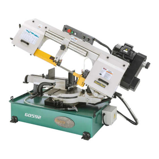
MODEL G0592
10" X 18" METAL-CUTTING
BANDSAW
OWNER'S MANUAL
(For models manufactured since 01/23)
COPYRIGHT © MAY, 2006 BY GRIZZLY INDUSTRIAL, INC., REVISED DECEMBER, 2022 (CS)
WARNING: NO PORTION OF THIS MANUAL MAY BE REPRODUCED IN ANY SHAPE
OR FORM WITHOUT THE WRITTEN APPROVAL OF GRIZZLY INDUSTRIAL, INC.
#PC7789 PRINTED IN TAIWAN
V2.12.22
***Keep for Future Reference***
Advertisement
Table of Contents

Related Manuals for Grizzly G0592


Summary of Contents for Grizzly G0592
- Page 1 OWNER'S MANUAL (For models manufactured since 01/23) COPYRIGHT © MAY, 2006 BY GRIZZLY INDUSTRIAL, INC., REVISED DECEMBER, 2022 (CS) WARNING: NO PORTION OF THIS MANUAL MAY BE REPRODUCED IN ANY SHAPE OR FORM WITHOUT THE WRITTEN APPROVAL OF GRIZZLY INDUSTRIAL, INC.
- Page 2 This manual provides critical safety instructions on the proper setup, operation, maintenance, and service of this machine/tool. Save this document, refer to it often, and use it to instruct other operators. Failure to read, understand and follow the instructions in this manual may result in fire or serious personal injury—including amputation, electrocution, or death.
-
Page 3: Table Of Contents
Table of Contents INTRODUCTION ..........2 SECTION 5: ACCESSORIES ......40 Contact Info............ 2 SECTION 6: MAINTENANCE ......42 Manual Accuracy ........... 2 Schedule ............42 Identification ........... 3 Cleaning & Protecting ........42 Controls & Components ......... 4 Lubrication ........... 42 Machine Data Sheet ........ -
Page 4: Introduction
ID label (see below). This information is required for us to provide proper tech support, and it helps us determine if updated documentation is available for your machine. Manufacture Date Serial Number Model G0592 (Mfd. Since 01/23) -
Page 5: Identification
Maintain proper adjustment of blade tension, blade guides, and thrust bearings. d) Adjust upper guide to just clear workpiece. e) Properly support and secure workpiece with table, vise, or some type of support fixture. Never hold workpiece with hands during cut. Model G0592 (Mfd. Since 01/23) -
Page 6: Controls & Components
98–394 FPM. Rotate knob clock- wise to decrease speed or counterclockwise to increase speed. IMPORTANT: To avoid damaging machine, ONLY change blade speed while main motor is running. E. Blade Tension Handle: Increases or decreases blade tension. Model G0592 (Mfd. Since 01/23) - Page 7 Coolant Valves: Control flow of coolant onto blade. O. Vise Lock Handles: Loosen to adjust vise base position in relation to blade; tighten to Spray Gun: Rinses metal chips into coolant secure vise base position. pan or drain filter. Model G0592 (Mfd. Since 01/23)
- Page 8 OFF at completion headstock at feed rate you have set. Turning of cutting arc. dial fully right locks headstock in position. R. Start Button: Turns main motor ON and acti- vates moving parts. Model G0592 (Mfd. Since 01/23)
-
Page 9: Machine Data Sheet
MACHINE DATA SHEET Customer Service #: (570) 546-9663 · To Order Call: (800) 523-4777 · Fax #: (800) 438-5901 MODEL G0592 10" X 18" METAL‐CUTTING BANDSAW Product Dimensions: Weight................................858 lbs. Width (side-to-side) x Depth (front-to-back) x Height..............72-1/2 x 32 x 58 in. - Page 10 The information contained herein is deemed accurate as of 11/28/2022 and represents our most recent product specifications. Model G0592 PAGE 2 OF 2 Due to our ongoing improvement efforts, this information may not accurately describe items previously purchased. Model G0592 (Mfd. Since 01/23)
-
Page 11: Section 1: Safety
Never operate under the influence of drugs or injury or blindness from flying particles. Everyday alcohol, when tired, or when distracted. eyeglasses are NOT approved safety glasses. Model G0592 (Mfd. Since 01/23) - Page 12 Make sure they are properly installed, you experience difficulties performing the intend- undamaged, and working correctly BEFORE ed operation, stop using the machine! Contact our operating machine. Technical Support at (570) 546-9663. -10- Model G0592 (Mfd. Since 01/23)
-
Page 13: Additional Safety For Horizontal Metal Bandsaws
Spilled cutting fluid invites slip- HOT SURFACES. Contact with hot surfaces from ping hazards. machine components, ejections of hot chips, swarf, and the workpiece itself can cause burns. -11- Model G0592 (Mfd. Since 01/23) -
Page 14: Section 2: Power Supply
To reduce the risk of these hazards, avoid over- loading the machine during operation and make sure it is connected to a power supply circuit that meets the specified circuit requirements. -12- Model G0592 (Mfd. Since 01/23) - Page 15 Minimum Gauge Size ......14 AWG service personnel, and it must comply with Maximum Length (Shorter is Better)..50 ft. all local codes and ordinances. -13- Model G0592 (Mfd. Since 01/23)
-
Page 16: Section 3: Setup
SECTION 3: SETUP IMPORTANT: Save all packaging materials until you are completely satisfied with the machine and have resolved any issues between Grizzly or the This machine presents shipping agent. You MUST have the original pack- serious injury hazards aging to file a freight claim. It is also extremely to untrained users. - Page 17 Figure 10. T23692 Orange Power Degreaser. Repeat Steps 2–3 as necessary until clean, then coat all unpainted surfaces with a quality metal protectant to prevent rust. -15- Model G0592 (Mfd. Since 01/23)
-
Page 18: Site Considerations
Only install in an Shadows, glare, or strobe effects that may distract access restricted location. or impede the operator must be eliminated. 72½" 32" Electrical Connection Figure 11. Minimum working clearances. -16- Model G0592 (Mfd. Since 01/23) -
Page 19: Lifting & Placing
Figure 13. Popular method for anchoring nuts included with machine, install these machinery to a concrete floor. by referring to Steps 1–2 of Assembly. — If you wish to anchor machine to floor, refer to Anchoring to Floor. -17- Model G0592 (Mfd. Since 01/23) -
Page 20: Assembly
It should be placed on same side where workpiece is being cut. Refer to Adjusting Work Stop on Page 36 for addi- tional details. -18- Model G0592 (Mfd. Since 01/23) -
Page 21: Power Connection
6-20 plug on the end of the power cord per the plug manufacturer's instructions. If no instruc- tions were included, use the wiring diagram on Page 61. Splash Guard Figure 18. Example of splash guard installed on base lip. -19- Model G0592 (Mfd. Since 01/23) -
Page 22: Test Run
Machine should not start. Turn feed rate dial to "1" (see Figure 19). — If machine does not start, safety feature of Emergency Stop/Off button is working Press Emergency Stop/Off button (see correctly. Figure 19). -20- Model G0592 (Mfd. Since 01/23) -
Page 23: Recommended Adjustments
Blade Tracking (Page 54). Blade Guide Bearings (Page 52). Squaring Blade to Table (Page 55). Handle (1 of 2) Downfeed Stop Bolt (Page 56). Coolant Valve (1 of 2) Figure 21. Coolant valves open. -21- Model G0592 (Mfd. Since 01/23) -
Page 24: Section 4: Operations
Regardless of the content in this sec- 15. Once machine has stopped, raises head- tion, Grizzly Industrial will not be held liable stock, turns machine OFF, and removes for accidents caused by lack of training. -
Page 25: Operation Tips
Cutting magnesium with a dull blade can cre- ate enough friction to ignite the small mag- nesium chips. Avoid cutting magnesium, if Loosen blade tension at the end of each day possible. to prolong blade life. -23- Model G0592 (Mfd. Since 01/23) -
Page 26: Using Vise
Loosen (2) vise locks handles (see Figure 24). Move vise base to opposite side of track (see Figure 24), then tighten vise lock handles to The vise on the Model G0592 can be positioned secure. for cutting on either side of the vise base, and consists of a movable vise jaw that can be adjust- ed to match the angle of the workpiece. -
Page 27: Selecting Blades
G. Tooth Pitch: Distance between tooth tips. H. Blade Back: Distance between bottom of gullet and back edge of blade. Blade Pitch or TPI: Number of teeth per inch measured from gullet to gullet. -25- Model G0592 (Mfd. Since 01/23) - Page 28 Material Width/Diameter Teeth Per Inch (TPI) for Bandsaw Blades Material Shapes TOOTH SELECTION 1.5/.8 1.4/2.5 1.4/2.5 1.5/.8 inch 2½ 3½ 14 15 Figure 29. General guidelines for blade selection and speed chart. -26- Model G0592 (Mfd. Since 01/23)
-
Page 29: Changing Blade
Remove (2) blade covers by loosening (8) knobs shown in Figure 30. Blade Cover (1 of 2) Blade Brush Assembly Figure 32. Example of removing blade brush assembly. Figure 30. Location of blade covers and knobs. -27- Model G0592 (Mfd. Since 01/23) - Page 30 (see Figure 36). Some blades will have a directional arrow as a guide. Blade Tension Handle Figure 36. Example of blade cutting direction. Figure 34. Location of blade tension handle. 10. Remove blade, beginning at top of blade wheels. -28- Model G0592 (Mfd. Since 01/23)
-
Page 31: Tensioning Blade
Wheel straight cuts, and efficient cutting. The Model Shoulder G0592 features a blade tension indicator to assist you with blade tensioning. The three major signs of incorrect blade tension are: 1) the blade stalls in the cut and slips on the wheels, and 2) the blade frequently breaks, and 3) the bandsaw does not make straight cuts. -
Page 32: Blade Breakage
The general rule of for blade tension. thumb is to have no fewer than three teeth in contact with the workpiece when starting a cut and at all times during cutting. -30- Model G0592 (Mfd. Since 01/23) -
Page 33: Blade Care & Break-In
The tips and edges of a new blade are extremely sharp. Cutting at too fast of a feed rate or too Model G0592 blade speeds: 98–394 FPM. slow of a blade speed can fracture these tips and edges, quickly dulling the blade. Properly break-... -
Page 34: Blade Speed Chart
Tool Steel (62) Steel (26) Cast Iron (98) Oil- Copper 229~482 203~213 85~203 Plastics & Hardened Stainless Alloy (70) (147) (62) (65) (26) (62) Lumber (67) Tool Steel Steel Figure 41. Blade speed chart. -32- Model G0592 (Mfd. Since 01/23) -
Page 35: Chip Inspection Chart
Hard, Coiled & Check Blade Silver Increase Decrease Thin Pitch Straight & Thin Silver Good Increase Powdery Silver Decrease Increase Coiled, Tight & Check Blade Silver Good Decrease Thin Pitch Figure 42. Chip inspection chart. -33- Model G0592 (Mfd. Since 01/23) -
Page 36: Setting Blade Feed Rate
Examine chips created from cutting opera- Lever tion, and adjust feed rate as necessary for optimum cutting performance (refer to Chip Inspection Chart on Page 33 for details). Figure 45. Location of swivel lock lever. -34- Model G0592 (Mfd. Since 01/23) - Page 37 Raise headstock all the way, then use feed control dial to keep it from lowering. Swivel Stop Loosen swivel lock lever (see Figure 47). Figure 49. Swivel stop engaged. Swivel Lock Lever Figure 47. Location of swivel lock lever. -35- Model G0592 (Mfd. Since 01/23)
-
Page 38: Adjusting Upper Blade Guide
Adjusting Upper Adjusting Work Stop Blade Guide The Model G0592 is equipped with a work stop for repetitive cutting operations. The work stop The upper blade guide should be as close to the can be installed on either side of the vise and workpiece as possible during cutting operations. -
Page 39: Using Coolant System
Work Stop follow federal, state, and cutting fluid manufacturer requirements to properly dispose of coolant. Figure 55. Example of work stop and arm installed on opposite side of rod. -37- Model G0592 (Mfd. Since 01/23) - Page 40 Coolant too little fluid at the cut will overheat the blade, Valves causing the blade teeth to load up and break. Figure 56. Location of coolant valves. -38- Model G0592 (Mfd. Since 01/23)
- Page 41 The chip screen shown in Figure 60 must also be kept clear so coolant can recycle to the coolant reservoir. Figure 61. Location of spray gun trigger. Chip Screen Figure 60. Location of chip screen. -39- Model G0592 (Mfd. Since 01/23)
-
Page 42: Section 5: Accessories
H1146—132" x 1" x .035" 3–4 Variable Pitch To reduce this risk, only install accessories H1147—132" x 1" x .035" 4–6 Variable Pitch recommended for this machine by Grizzly. H1148—132" x 1" x .035" 5–8 Variable Pitch H1149—132" x 1" x .035" 6–10 Variable Pitch NOTICE H1150—132"... - Page 43 Won’t gum up! 12 oz. AMGA#2 (ISO 68 Equivalent) Figure 68. T28042 Moly-D Gear Oil. Figure 66. SB1365 Way Oil. www.grizzly.com 1-800-523-4777 order online at or call -41- Model G0592 (Mfd. Since 01/23)
-
Page 44: Section 6: Maintenance
To reduce risk of shock or accidental startup, always disconnect machine from power before adjustments, Cleaning the Model G0592 is relatively easy. Use maintenance, or service. a brush and shop vacuum to remove chips and other debris from the working surfaces. - Page 45 Figure 71. threads (see Figure 73). Leadscrew Pivot Grease Fittings Figure 73. Location of vise leadscrew. Figure 71. Location of pivot grease fittings. -43- Model G0592 (Mfd. Since 01/23)
- Page 46 Run machine for 10 minutes to warm up oil in DISCONNECT MACHINE FROM POWER! gearbox. Lower headstock completely. DISCONNECT MACHINE FROM POWER! Raise headstock all the way, then use feed control dial to keep it from lowering. -44- Model G0592 (Mfd. Since 01/23)
-
Page 47: Coolant System Maintenance
(refer to Checking/Adding when handling coolant. Gearbox Oil on Page 44). Follow federal, state, and cutting fluid manu- facturer requirements for proper disposal. -45- Model G0592 (Mfd. Since 01/23) - Page 48 Remove (6) Phillips head screws and flat washers shown in Figure 81 to remove stand cover. Stand Cover Sight Gauge Figure 79. Location of sight gauge. Figure 81. Location of stand cover and fasteners. -46- Model G0592 (Mfd. Since 01/23)
-
Page 49: Storing Machine
— If machine will be out of service for only a short period of time, start machine once a week and run all gear-driven components for a few minutes. This will put fresh coat of gear oil on gearing components inside gearbox. -47- Model G0592 (Mfd. Since 01/23) - Page 50 Repeat Steps 3–4 as necessary until clean. Check gear oil level (see Checking/Adding Gear Oil on Page 44). Install or tension blade as described on Page 27 or 29. Perform Test Run on Page 20. -48- Model G0592 (Mfd. Since 01/23)
-
Page 51: Section 7: Service
10. Machine undersized for task. depth of cut; use cutting fluid if possible. 11. Motor overheated, tripping machine circuit 11. Clean motor, let cool, and reduce workload. Reset breaker. breaker. 12. Run capacitor at fault. 12. Test/repair/replace. -49- Model G0592 (Mfd. Since 01/23) - Page 52 6. Verify blade has at least 3 teeth contacting material at all times (Page 25). 7. Clean wheels; increase blade tension (Page 29). 7. Blade tension too low. 8. Use applicable coolant/lubricant (Page 37). 8. Material requires cutting fluid/lubrication. -50- Model G0592 (Mfd. Since 01/23)
- Page 53 2. Check/fill coolant (Page 46). 2. Coolant level is low. functioning. 3. Coolant system is leaking. 3. Inspect/test for leaks; repair. 4. Flow blocked or impeded. 4. Make sure coolant line(s) are not pinched, plugged, or damaged. -51- Model G0592 (Mfd. Since 01/23)
-
Page 54: Adjusting Blade Guide Bearings
Loosen (2) knobs shown in Figure 85 to remove lower rear blade guard. Remove (2) Phillips head screws and flat washers shown in Figure 85 to remove upper Front rear blade guard. Blade Guard Figure 83. Front blade guard and knobs. -52- Model G0592 (Mfd. Since 01/23) - Page 55 Repeat Steps 1–5 on lower blade guide. Install blade guards. Adjust blade brush (see Adjusting Blade Eccentric Brush on Page 56). (1 of 2) Blade Guide Bearing (1 of 6) Figure 86. Location of blade guide bearing adjustment components. -53- Model G0592 (Mfd. Since 01/23)
-
Page 56: Adjusting Blade Tracking
Remove (2) blade covers by loosening (8) knobs shown in Figure 88. Tracking Blade Cover Cap Screw (1 of 2) Figure 90. Location of tracking cap screw. Install blade covers. Figure 88. Location of blade covers and knobs. -54- Model G0592 (Mfd. Since 01/23) -
Page 57: Squaring Blade To Table
Tip: Cut small sections from scrap piece of material with known square end and mea- sure for uniform thickness. If thickness is not uniform, repeat adjustments above until your personal requirements are met. Figure 91. Checking blade squareness. -55- Model G0592 (Mfd. Since 01/23) -
Page 58: Adjusting Blade Brush
Adjusting Blade Brush Downfeed Stop Bolt The Model G0592 has a blade brush to help keep If the blade does not travel far enough to complete metal chips off the blade wheels. Use this sec- the cut, or the blade contacts the vise base, then tion to install the brush correctly after installing a the downfeed stop bolt will need to be adjusted. -
Page 59: Adjusting Angle Stops
Pivot Bracket Figure 97. Example of testing blade-to-vise squareness. Figure 96. Location of limit switch adjustment — If square fits snugly against fixed jaw and components. blade, no adjustment is necessary. Tighten cap screws. -57- Model G0592 (Mfd. Since 01/23) - Page 60 Figure 99. Example of 60° stop bolt contacting base (left 60° stop shown). Figure 101. Location of 60° stop bolt jam nut (left 60° stop shown). Move vise to opposite side of track than headstock was swiveled in Step 3. -58- Model G0592 (Mfd. Since 01/23)
-
Page 61: Tensioning/Replacing V-Belt
Belt Cover (1 of 2) Pulley Deflection ⁄ " Belt Cover Pulley Figure 104. Checking belt deflection. Figure 102. Location of variable-speed belt covers, belt cover, and screws. Install belt cover. Install variable-speed belt covers. -59- Model G0592 (Mfd. Since 01/23) -
Page 62: Section 8: Wiring
Technical Support at (570) 546-9663. The photos and diagrams included in this section are best viewed in color. You can view these pages in color at www.grizzly.com. -60- Model G0592 (Mfd. Since 01/23) -
Page 63: Wiring Diagram
MOTOR 88 SERIES 220V RUN CAPACITOR 3uF 400V CONTACTOR TECO CU-18 RELAY TRANSFORMER LCE LCPIC-TBSW-100030 ERSCE ES50 FUSE 1109540 OL RELAY TECO RHU-10/16K1 6-20 Plug (as recommended) ELECTRICAL READ ELECTRICAL SAFETY -61- Model G0592 (Mfd. Since 01/23) ON PAGE 60! -
Page 64: Electrical Component Photos
Electrical Component Photos Figure 105. Control panel wiring. Figure 108. Limit switch wiring. Figure 106. Start capacitor wiring. Figure 109. Pump motor wiring. Figure 107. Motor junction box wiring. READ ELECTRICAL SAFETY -62- Model G0592 (Mfd. Since 01/23) ON PAGE 60! - Page 65 Electrical Component Photos (Cont.) Figure 110. Electrical box wiring. READ ELECTRICAL SAFETY -63- Model G0592 (Mfd. Since 01/23) ON PAGE 60!
-
Page 66: Section 9: Parts
SECTION 9: PARTS We do our best to stock replacement parts when possible, but we cannot guarantee that all parts shown are available for purchase. Call (800) 523-4777 or visit www.grizzly.com/parts to check for availability. Base 29-4 29-3 29-2 29-7... - Page 67 CONNECTOR 3-WAY 14-1 P0592014-1 R CAPACITOR 3M 400V 29-8 P0592029-8 STRAIGHT CONNECTOR P0592015 RUBBER GASKET P0592031 PHLP HD SCR M5-.8 X 12 BUY PARTS ONLINE AT GRIZZLY.COM! -65- Model G0592 (Mfd. Since 01/23) Scan QR code to visit our Parts Store.
-
Page 68: Swivel Base
Swivel Base BUY PARTS ONLINE AT GRIZZLY.COM! -66- Model G0592 (Mfd. Since 01/23) Scan QR code to visit our Parts Store. - Page 69 PHLP HD SCR M6-1 X 6 P0592131 FLAT WASHER 10MM P0592164 SWITCH ADJUSTING BRACKET P0592132 LOCK WASHER 10MM P0592165 HEX BOLT M5-.8 x 10 BUY PARTS ONLINE AT GRIZZLY.COM! -67- Model G0592 (Mfd. Since 01/23) Scan QR code to visit our Parts Store.
-
Page 70: Vise
Vise 215-1 215-2 BUY PARTS ONLINE AT GRIZZLY.COM! -68- Model G0592 (Mfd. Since 01/23) Scan QR code to visit our Parts Store. - Page 71 CAP SCREW M8-1.25 X 25 P0592247 DISTANCE SET ROD P0592223 LOCK WASHER 8MM P0592250 SET SCREW M8-1.25 X 20 P0592224 RACK SUPPORT BUY PARTS ONLINE AT GRIZZLY.COM! -69- Model G0592 (Mfd. Since 01/23) Scan QR code to visit our Parts Store.
-
Page 72: Headstock
BLADE 132 X 1 X .032" 6/10TPI P0592706 HEX NUT M8-1.25 P0592421 CAP SCREW M10-1.5 X 20 P0592709 BLADE BACK COVER BUY PARTS ONLINE AT GRIZZLY.COM! -70- Model G0592 (Mfd. Since 01/23) Scan QR code to visit our Parts Store. -
Page 73: Blade Tension & Motor
Blade Tension & Motor 478-3 478-4 478-1 478-6 478-2 478-5 478-7 461-1 461-2 482-1 BUY PARTS ONLINE AT GRIZZLY.COM! -71- Model G0592 (Mfd. Since 01/23) Scan QR code to visit our Parts Store. - Page 74 HANDLE BODY P0592479 SHAFT P0592520 THRUST BEARING 51204 P0592480 CAP SCREW M10-1.5 X 60 P0592521 ANCHOR BLOCK P0592481 HEX NUT M12-1.75 BUY PARTS ONLINE AT GRIZZLY.COM! -72- Model G0592 (Mfd. Since 01/23) Scan QR code to visit our Parts Store.
-
Page 75: Blade Guides
Blade Guides 556-6 556-5 556-4 556-3 556-2 556-1 580 579V2 589-1 589-5 589-4 589-3 589-2 551-3 551-2 551-1 550-3 550-2 550-1 BUY PARTS ONLINE AT GRIZZLY.COM! -73- Model G0592 (Mfd. Since 01/23) Scan QR code to visit our Parts Store. - Page 76 P0592595 ARM RIGHT P0592565 BLADE GUARD FRONT P0592596 SET SCREW M8-1.25 X 25 P0592568 FLAT WASHER 6MM P0592597 HEX NUT M8-1.25 BUY PARTS ONLINE AT GRIZZLY.COM! -74- Model G0592 (Mfd. Since 01/23) Scan QR code to visit our Parts Store.
-
Page 77: Electrical
PHLP HD SCR M5-.8 X 12 713-10 P0592713-10 FUSE 713-29V2 P0592713-29V2 FEED RATE DIAL V2.12.08 713-11 P0592713-11 BRACKET 713-30V2 P0592713-30V2 FEED/SPEED CONTROL DIAL V2.12.08 BUY PARTS ONLINE AT GRIZZLY.COM! -75- Model G0592 (Mfd. Since 01/23) Scan QR code to visit our Parts Store. -
Page 78: Labels & Cosmetics
Safety labels help reduce the risk of serious injury caused by machine hazards. If any label comes off or becomes unreadable, the owner of this machine MUST replace it in the original location before resuming operations. For replacements, contact (800) 523-4777 or www.grizzly.com. BUY PARTS ONLINE AT GRIZZLY.COM! -76- Model G0592 (Mfd. -
Page 79: Warranty & Returns
WARRANTY & RETURNS Grizzly Industrial, Inc. warrants every product it sells for a period of 1 year to the original purchaser from the date of purchase. This warranty does not apply to defects due directly or indirectly to misuse, abuse, negligence, accidents, repairs or alterations or lack of maintenance.