Advertisement
MicroVerb/
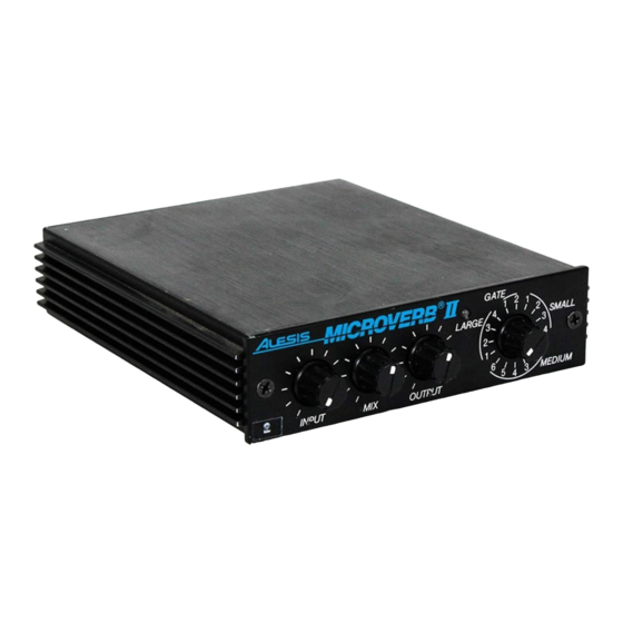
Microverb II
Service Manual
THIS DOCUMENT CONTAINS SENSITIVE
PROPRIETARY INFORMATION.
ALL RECIPIENTS MUST HAVE A CURRENT
NON-DISCLOSURE AGREEMENT ON FILE
COPIES OF THIS DOCUMENT
The information in this document contains privileged and confidential information.
It is intended only for the use of those authorized by Alesis. If you are not the
authorized, intended recipient, you are hereby notified that any review,
dissemination, distribution or duplication of this document is strictly prohibited. If
you are not authorized, please contact Alesis and destroy all copies of this
document. You may contact Alesis at servicemanuals@alesis.com or at
support@alesis.com.
Copyright Alesis, LLC
Confidential
ALESIS
(C1/C2)
P/N: 8-31-0160-A
ATTENTION!
WITH ALESIS, LLC.
DO NOT MAKE ILLEGAL
Alesis Service Manual
8-31-0160-A
Advertisement
Table of Contents

Related Manuals for Alesis MicroVerb


Summary of Contents for Alesis MicroVerb
- Page 1 COPIES OF THIS DOCUMENT The information in this document contains privileged and confidential information. It is intended only for the use of those authorized by Alesis. If you are not the authorized, intended recipient, you are hereby notified that any review, dissemination, distribution or duplication of this document is strictly prohibited.
- Page 2 Your purchase of the Manual shall be for your own ultimate use and shall not be for purposes of resale or other transfer. As the owner of the copyright to the Manual, Alesis does not give you the right to copy the Manual, and you agree not to copy the Manual without the written authorization of Alesis. Alesis has no obligation to provide to you any correction of, or supplement to, the Manual, or any new or superseding version thereof.
- Page 3 ALL REPAIRS DONE BY ANY ENTITY OTHER THAN AN AUTHORIZED ALESIS SERVICE CENTER SHALL BE SOLELY THE RESPONSIBILITY OF THAT ENTITY, AND ALESIS SHALL HAVE NO LIABILITY TO THAT ENTITY OR TO ANY OTHER PARTY FOR ANY REPAIRS BY THAT ENTITY.
-
Page 4: Safety Instructions
The product is exposed to water or excessive moisture, c. The AC power supply plug or cord is damaged, d. The product shows an inappropriate change in performance or does not operate normally, or e. The enclosure of the product has been damaged. Confidential Alesis Service Manual 8-31-0160-A... -
Page 5: General Description
2.0 Power Supply The power supply begins with the 9 Volt A.C., adapter (Alesis P2 type). Input from J6 is R.F. filtered by C1. From there it is split for the +12V, -12V, and +5V rails. The +12V rail consists of a voltage doubler (C5, C6, and D2, D4), a 7812 regulator (VR2), and filter capacitors (C10, C21). -
Page 6: Digital Signal Paths
Controls sample and hold circuit timing. ADCDATA A/D comparison input. CLOCK ASIC Clock input (6MHz for MicroVerb or 8Mhz for MicroVerb II) This signal indicates a math overflow condition, and consequently turns on the clip LED circuit. ERROR LSTMSB This signal indicates the last state of the MSB (the sign bit in two's complement math). This signal, in conjunction with R27, R29, R44, and C17, is used to bias the incoming analog signal slightly positive, or negative, depending on the result of the last DAC cycle (i.e. - Page 7 The process begins with the input "sample and hold circuit". 1 switch of U9 (4053) is turned on, allowing the input sample capacitor (C20) to charge (or discharge) to the level of the current input signal. When the switch is turned off, the capacitor will hold that level indefinitely MicroVerb/MicroVerb II Service Manual 1.00 3/7/2003...
-
Page 8: Updates And Corrections
6.3 C20 Large Mylar capacitors in this position should be replaced with film capacitors. (again because of excessive leakage). A failure of this capacitor will cause distorted effects (wet signal). MicroVerb/MicroVerb II Service Manual 1.00 3/7/2003... -
Page 9: Test Procedures
Turn the input level all the way down, and the output level all the up. Listen for excessive noise in the noise floor. As a final check it's a good idea to physically shake the unit so that no loose parts remain inside the unit. MicroVerb/MicroVerb II Service Manual 1.00 3/7/2003... - Page 10 Replace and retest. Intermittent effects. C23 leaking somewhat. Replace and retest. Faulty shaft encoder Replace and retest. Bypass jack normaling contact is dirty. Troubleshoot and replace if necessary. All trademarks are property of their respective companies. MicroVerb/MicroVerb II Service Manual 1.00 3/7/2003...
- Page 11 ALESIS MicroVerb/ Microverb II (C1/C2) HISTORY Confidential Alesis Service Manual 8-31-0160-A...
- Page 13 ALESIS MicroVerb/ Microverb II (C1/C2) Confidential Alesis Service Manual 8-31-0160-A...
-
Page 14: Service Parts List
9.0 Service Parts List Note: This list reflects resistor and capacitor values for the MicroVerb II. Care should be taken when repairing the original MicroVerb to replace these components with the original value (not the one listed here for the MicroVerb II).