Table of Contents
Advertisement
Advertisement
Table of Contents

Related Manuals for Alesis MidiVerb 3


Summary of Contents for Alesis MidiVerb 3
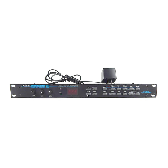
- Page 1 ALESIS MidiVerb 3 (M3) Service Manual P/N: 8-31-0014-A...
- Page 2 Your purchase of the Manual shall be for your own ultimate use and shall not be for purposes of resale or other transfer. As the owner of the copyright to the Manual, Alesis does not give you the right to copy the Manual, and you agree not to copy the Manual without the written authorization of Alesis. Alesis has no obligation to provide to you any correction of, or supplement to, the Manual, or any new or superseding version thereof.
- Page 3 ALL REPAIRS DONE BY ANY ENTITY OTHER THAN AN AUTHORIZED ALESIS SERVICE CENTER SHALL BE SOLELY THE RESPONSIBILITY OF THAT ENTITY, AND ALESIS SHALL HAVE NO LIABILITY TO THAT ENTITY OR TO ANY OTHER PARTY FOR ANY REPAIRS BY THAT ENTITY.
- Page 4 Safety Instructions Carefully read the applicable items of the operating instructions and these safety suggestions before using this product. Use extra care to follow the warnings written on the product itself and in the operating instructions. Keep the operating instructions and safety suggestions for reference in the future. 1.
- Page 5 1.0 M3 GENERAL DESCRIPTION The M3, and other digital effects processors, achieve their results by slicing analog signals into segments, and then converting them to a numeric value, corresponding to the amplitude of the signal at that particular instant. These values are then mathematically manipulated, and stored at various locations in a memory "loop"...
- Page 6 3.0 ANALOG SIGNAL PATHS The inputs (stereo) from J1 and J2 pass through the small toroids for RF suppression (bypassed in some units), A.C. coupled (C1, C2) and have their impedances fixed at 1M by R2 and R3. While operating the unit monauraly, the input impedance fixed at 500K (R2, and R3, in parallel). From there, the inputs are buffered by U1, and passed through the input potentiometers.
- Page 7 compared. This process continues until a value is found for all 16 bits, and the data is ready for further processing by the ASIC. In order to see these signals properly on the scope, it will be necessary to use an external scope sync (use U6, pin 9 as the sync source). Diagrams 2, and 3, show the DAC output during a single SAR cycle, with no input, and full input.
- Page 8 so critical throughout this circuit that parts that are even slightly out of spec will cause failures. This is due to the fact that propagation delay times are not only significant, but inherently part of the design. If the logic seems a bit confusing at first, it helps to remember that many of the target signals are active low.
- Page 9 4.4.2 8031 Reads From Memory 8031 reads from memory begin as any normal read would. The 8031 sets up the address the address buss (see section 4.1 for details) and presents it to the SRAM via U26 (A0-A7) and U15 (A8- A10).
- Page 10 Signal Function SRAM output enable. - 6MHz clock - RESET - Controls sample and hold circuit timing. LSTMSB - This signal indicates the last state of the MSB (the sign bit in two's complement math). Note at this point that there are two different ASICs. One is made by Fujitsu, the other by AMI.
- Page 11 6.0 UPDATES AND CORRECTIONS 6.1 CABLES Check all connector cables are firmly seated. In some cases, they can come 1/2 way off. 6.2 U17 If U17 (74HC139) is a type made by National semiconductor, it should be replaced with a type made by TI.
- Page 12 Customer Complaint Possible Failure Possible Action No Power, No Lights, No Life Blown DASP 8 ASIC. If this IC is extremely hot, to the touch, then it is faulty. Bad +5V rectifier diode (D22) The cathode should read roughly 10V (with some ripple). It has been noticed that 1N4001 seem to have problems, and since then have started using 1N4003...
- Page 13 8.0 SOFTWARE HISTORY DATE VERSION COMMENTS 10/9/89 1.00 First production release 10/25/90 1.01 1) MIDI system exclusive dump request (F0 00 00 0E 03 02 F7) was not being responded to properly. Receiving this command will now cause the MIDIVERB III to send out a complete sysex dump of its programs.
- Page 14 9.0 M3 MIDI IMPLEMENTATION (SYSTEM EXCLUSIVE) SYSTEM EXCLUSIVE FORMAT The Midiverb III MIDI System Exclusive message format is as follows: System exclusive status 00 00 0E Alesis manufacturer id# Midiverb III id# Opcode Data End-Of-Exclusive OPCODES: 00 - Complete MIDI Data Dump F0 00 00 0E 03 00 <data> F7 <data>...
- Page 15 Bytes 1600-1615 consist of the same data as above, and relates to the current edit buffer. Bytes 1616 through 1621 are as follows: 1616: Current program number (000-199) 1617: Current edit buffer edited (0=no / dot off, 1=yes / dot on) 1618: Current program step displayed at MIDI PROG page 1619: MIDI echo off/on (0/1) 1620: MIDI channel (0-15)
- Page 16 03 - MIDI Editing F0 00 00 0E 03 03 <parameter#> < value lsb> < value msb> F7 <parameter#> = 0000ppppB as follows: parameter range parameter range 0=INPUT EQ 0-30 1=EFFECT EQ 0-30 2=CHORUS ALGORITHM 0-24 3=CHORUS SPEED 0-98 4=DELAY TIME 1-100* 5=DELAY REGEN 0-99 6=REVERB ALGORITHM 0-19...
- Page 17 ALESIS MidiVerb 3 (M3) SCHEMATIC FILES Confidential Alesis Service Manual 8-31-0014-A...
- Page 21 10.0 M3 Service Parts List GROUP DESCRIPTION PART# QNTY POSITION MANUFACT NOTES PCB, M3 MAIN ASSY 8-20-0052 MAIN BOARD ASSEMBLY PCB, LED ASSY 8-20-0049 LED (FRONT PANEL) BOARD ASSEMBLY 12 PIN SIL 3 0.1 CTR 4-19-0312 MAIN-F/P 12 PIN SIL 7 0.1 CTR 4-19-0712 MAIN-F/P...
- Page 22 4053 ANALOG SWITCH 2-23-4053 MAIN ST/HAR/RCA/SIG 16 PIN DIP 0.3 6N138 OPTOISO 2-24-0138 MAIN SIEMANS/HP 8 PIN DIP 0.3 2Kx8 SRAM 6116 2-17-0128 MAIN CYPRESS 24 PIN DIP 0.3 32Kx8 SRAM 2-17-0257 U8 (LOW POWER) MAIN SONY 28 PIN DIP 0.6 2Kx8 EEPROM X2816CP-20 2-19-0002 MAIN...
- Page 23 47K 1/8W 5% 0-00-0473 R11,16 MAIN 470K 1/8W 5% 0-00-0474 MAIN 4.7M 1/8W 5% 0-00-0475 MAIN 510K 1/8W 5% 0-00-0514 R47,250 MAIN 560 1/8W 5% 0-00-0561 R60-67,76-88,97,109-112 MAIN 680 1/8W 5% 0-00-0681 R29,30 MAIN 6.8K 1/8W 5% 0-00-0682 R23-26 MAIN 250K TRIMPOT 0-08-0254 MAIN...