
Related Manuals for EverFocus eIVP-EHL Series


Summary of Contents for EverFocus eIVP-EHL Series
- Page 1 eIVP-EHL_Series eIVP-EHL-IV-V0000 In-Vehicle System eIVP-EHL-AI-D0000 Fanless AI Box User’s Manual Copyright © EverFocusElectronics Corp. Release Date: December 2022...
- Page 2 All rights reserved. No part of the contents in this manual may be reproduced or transmitted in any form or by any means without written permission of the EverFocus Electronics Corporation. Microsoft Windows is a registered trademark of Microsoft Corp;...
- Page 3 All cautions and warnings on the device should be noted. All cables and adapters supplied by EverFocus are certified and in accordance with the material safety laws and regulations of the country of sale. Do not use any cables or adapters not supplied by EverFocus to prevent system malfunction or fires.
- Page 4 FCC Statement This device complies with Part 15 FCC Rules. Operation is subject to the following two conditions: (1) this device may not cause harmful interference, and (2) this device must accept any interference received including interference that may cause undesired operation. Caution: There is a danger of explosion if the battery is incorrectly replaced.
-
Page 5: Table Of Contents
Table Of Content Introduction ............................ 1 Features ............................. 1 Dimensions ............................2 Packing List ............................3 Front Panel I/O & Functions ......................4 Rear Panel I/O & Functions ....................... 4 1.5.1 PWR Input ............................5 1.5.2 Alarm I/O ............................5 Connector / Jumper Locations ...................... - Page 6 1.8.23 M.2 Slot (E-Key 2230)(CN26) ....................28 1.8.24 COM Port 1~4(CN27) ....................... 30 1.8.25 eSPI Debug Port(CN32) ......................31 1.8.26 CPU FAN(CN33) ........................32 1.8.27 External Power Input(CN34) ....................32 1.8.28 External Power Input(CN35) ....................32 1.8.29 Front Panel Connector(CN36) ....................33 1.8.30 PSE Connector(CN37) .......................
- Page 7 3.5.1 System Agent (SA) Configuration ....................62 3.5.1.1 Memory Configuration ......................62 3.5.1.2 LVDS Panel Configuration ......................63 Setup Submenu: Security ........................ 64 3.6.1 Secure Boot ..........................65 3.6.1.1 Key Management ........................66 Setup Submenu: Boot ........................68 3.7.1 BBS Priorities ..........................68 Setup Submenu: Save &...
-
Page 8: Introduction
Featuring 32GB of DDR4 3200MHz memory and advanced Intel® Iris® Xe graphics, this series are capable of multiple displays with 4K Resolution. In support of high-speed connectivity such as USB (10G) and GbE LAN (2.5G), eIVP-EHL Series can support low-latency data transmission for wider industrial use cases and AI-oriented workloads. -
Page 9: Dimensions
eIVP-EHL-AI-D0000 eIVP-EHL-IV-V0000 1.2 Dimensions eIVP-EHL-IV-V0000 Unit: mm / inch eIVP-EHL-AI-D0000 Unit: mm / inch... -
Page 10: Packing List
Note: 1. Equipment configurations and supplied accessories vary by country. Please consult your local EverFocus office or agents for more information. Please also keep the shipping carton for possible future use. 2. Contact the shipper if any items appear to have been damaged in the shipping process. -
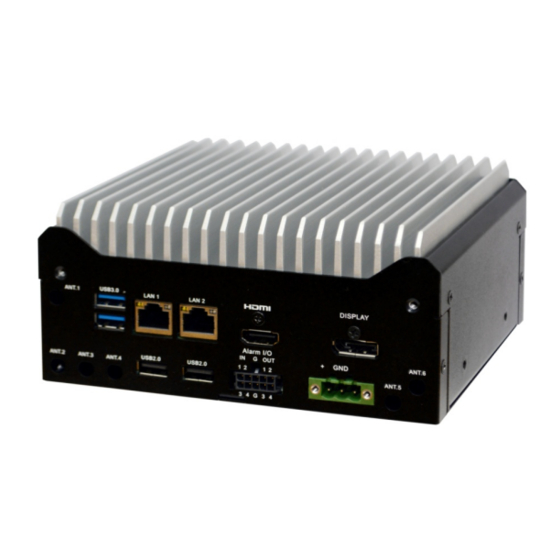
Page 11: Front Panel I/O & Functions
eIVP-EHL-AI-D0000 eIVP-EHL-IV-V0000 1.4 Front Panel I/O & Functions Name Description Press the button to turn on or turn off the system. Power Button HDD: When storage is reading/writing data, the LED will flashes Indicator/Reset green Reset button : Press the button to restart the system. Connects to audio input / output devices, such as microphones / speakers. -
Page 12: Pwr Input
eIVP-EHL-AI-D0000 eIVP-EHL-IV-V0000 Alarm I/O Audio In/Out. Please refer to 1.5.2 Alarm I/O Ethernet GbE LAN x 2 USB2.0 USB2.0 port x 2 USB3.0 USB3.0 port x 2 1.5.1 PWR Input Power Input 1.5.2 Alarm I/O Alarm In Alarm Out... -
Page 13: Connector / Jumper Locations
eIVP-EHL-AI-D0000 eIVP-EHL-IV-V0000 1.6 Connector / Jumper Locations 1.6.1 eIVP-EHL-IV-V0000 & eIVP-EHL-AI-D0000 Main Board Top Side View... -
Page 14: Eivp-Ehl-Iv-V0000 & Eivp-Ehl-Ai-D0000 Main Board Bottom Side View
eIVP-EHL-AI-D0000 eIVP-EHL-IV-V0000 1.6.2 eIVP-EHL-IV-V0000 & eIVP-EHL-AI-D0000 Main Board Bottom Side View 1.7 List of Jumpers Please refer to the table below for all of the board’s jumpers that you can configure for your application. Label Function Clear CMOS Jumper Touch Screen 4/5/8-wire Mode Selection LVDS Port Backlight Inverter VCC Selection LVDS Port Operating VDD Selection LVDS Port Backlight Lightness Control Mode Selection... -
Page 15: Clear Cmos Jumper(Jp1)
eIVP-EHL-AI-D0000 eIVP-EHL-IV-V0000 1.7.1 Clear CMOS Jumper(JP1) 1.7.2 Touch Screen 4, 5, 8 Wire Selection (JP2) 1.7.3 LVDS Port Backlight Inverter VCC Selection (JP3) 1.7.4 LVDS Port Operating VDD Selection (JP4) 1.7.5 LVDS Port Backlight Lightness Control Mode Selection (JP5) -
Page 16: Auto Power Button Enable/Disable Selection (Jp6)
eIVP-EHL-AI-D0000 eIVP-EHL-IV-V0000 1.7.6 Auto Power Button Enable/Disable Selection (JP6) 1.7.7 COM2 Pin8 Function Selection (JP8) 1.7.8 COM3 Pin8 Function Selection (JP9) 1.7.9 SMBUS/I2C Connector (JP11) Signal Type Signal Type SMBUS DATA / I2C DATA +3.3V SMBUS CLK / I2C CLK +1.8V SMBUS INT / INT SERIRQ Default: SMBUS. -
Page 17: List Of Connectors
eIVP-EHL-AI-D0000 eIVP-EHL-IV-V0000 1.8 List of Connectors Please refer to the table below for all of the board’s connectors that you can configure for your application Label Function Battery Touch Screen Connector Audio I/O Port Amplifier R-channel output Amplifier L-channel output M.2 B-Key 3052 (USB 3.2 GEN2 / USB 2.0) Nano SIM Card Socket M.2 B-Key 2242 (PCIe x2 or SATA III) -
Page 18: Battery (Cn1)
eIVP-EHL-AI-D0000 eIVP-EHL-IV-V0000 1.8.1 Battery (CN1) Pin Name Signal Type Signal Level +3.3V 3.3V 1.8.2 Touch Screen Connector (CN2) 8Wires Pin Name Signal Type Signal level TOP EXCITE BOTTOM EXCITE LEFT EXCITE RIGHT EXCITE TOP SENSE BOTTOM SENSE LEFT SENSE RIGHT SENSE 4Wires Pin Name Signal Type... -
Page 19: Audio I/O Port(Cn3)
eIVP-EHL-AI-D0000 eIVP-EHL-IV-V0000 Pin Name Signal Type Signal level UL(Y) UR(H) LL(L) LR(X) SENSE(S) 1.8.3 Audio I/O Port(CN3) Pin Name Signal Type Signal level LINE_R_OUT MIC_R LINE_L_OUT MIC_L JD_LINE OUT JD_MIC IN GND_AUDIO GND_AUDIO JD_LINE IN LINE_R_IN +5V_AUDIO LINE_L_IN... -
Page 20: Amplifier R-Channel Output(Cn4)
eIVP-EHL-AI-D0000 eIVP-EHL-IV-V0000 1.8.4 Amplifier R-channel output(CN4) Pin Name Signal Type Signal level SKR_R+ SKR_R- 1.8.5 Amplifier L-channel output(CN5) Pin Name Signal Type Signal level SKR_L+ SKR_L- 1.8.6 M.2 Slot (B-Key3052)(CN6) Pin Name Signal Type Signal level +3.3V +3.3V +3.3V +3.3V USB_D+ DIFF W_DISABLE... - Page 21 eIVP-EHL-AI-D0000 eIVP-EHL-IV-V0000 SSD_DAS# USB_RX- DIFF UIM_RST USB_RX+ DIFF UIM_CLK UIM_DAT IN / OUT USB_TX- DIFF UIM_PWR USB_TX+ DIFF DEVSLP GF_SM_CLK GF_SM_DAT IN / OUT PERST# PEWAKE#...
-
Page 22: Nano Sim Card Socket(Cn7)
eIVP-EHL-AI-D0000 eIVP-EHL-IV-V0000 +3.3V +3.3V +3.3V +3.3V +3.3V +3.3V 1.8.7 Nano SIM Card Socket(CN7) Pin Name Signal Type Signal level UIM_PWR UIM_RST UIM_CLK UIM_VPP UIM_DATA... -
Page 23: Slot (B-Key2242)(Cn8)
eIVP-EHL-AI-D0000 eIVP-EHL-IV-V0000 1.8.8 M.2 Slot (B-Key2242)(CN8) Pin Name Signal Type Signal level +3.3V +3.3V +3.3V +3.3V W_DISABLE SSD_DAS# PCIE_RX- DIFF PCIE_RX+ DIFF PCIE_TX- DIFF PCIE_TX+ DIFF DEVSLP... - Page 24 eIVP-EHL-AI-D0000 eIVP-EHL-IV-V0000 PCIE0_RX- / PCIE0_RX+ / PCIE0_TX- / PCIE0_TX+ / PERST# CLKREQ# PCIE_CLK- PEWAKE# PCIE_CLK+ +3.3V +3.3V +3.3V +3.3V +3.3V +3.3V Note: The speed of PCIe for CN8 can be changed by BIOS and be changed to mSATA by BOM. Default: PCIe x2...
-
Page 25: Lvds/Edp Port Inverter / Backlight Connector (Cn9)
eIVP-EHL-AI-D0000 eIVP-EHL-IV-V0000 1.8.9 LVDS/eDP Port Inverter / Backlight Connector (CN9) Pin Name Signal Type Signal level BKL_PWR +5V / +12V BKL_PWR +5V / +12V BKL_CONTROL BKL_ENABLE Note1: LVDS BKL_PWR can be set to +5V or +12V by JP3 Note2: LVDS BKL_CONTROL can be set by JP5 1.8.10 LVDS/eDP Port(CN10) LVDS Function Pin Name... -
Page 26: Hdmi(Cn11)
eIVP-EHL-AI-D0000 eIVP-EHL-IV-V0000 LVDS_DA0+ / EDP_LANE DIFF LVDS_DA2+ / EDP_LANE DIFF LVDS_DA1- / EDP_LANE DIFF LVDS_DA3- DIFF LVDS_DA1+ / EDP_LANE DIFF LVDS_DA3+ DIFF LVDS_DB0- DIFF +3.3V DDC_DATA / EDP_AUX- I/O / LVDS_DB0+ DIFF +3.3V DDC_CLK / EDP_AUX+ I/O / LVDS_DB1- DIFF LVDS_DB2- DIFF Note: LVDS LCD_PWR can be set to +3.3V or +5V by JP4... -
Page 27: Dp Port(Cn13)
eIVP-EHL-AI-D0000 eIVP-EHL-IV-V0000 HDMI_D0+ DIFF HDMI_D0- DIFF HDMI_CLK+ DIFF HDMI_CLK- DIFF HDMI_SLK HDMI_SDA IN/OUT HPLG_DETECT 1.8.12 DP Port(CN13) Pin Name Signal Type Signal level DP_D0+ DIFF DP_D0- DIFF DP_D1+ DIFF DP_D1- DIFF DP_D2+ DIFF DP_D2- DIFF DP_D3+ DIFF DP_D3- DIFF DDI2_OB_AUX_EN... -
Page 28: Lan (Rj-45) Port1(Cn14)
eIVP-EHL-AI-D0000 eIVP-EHL-IV-V0000 DP_AUX+ / DIFF DP_AUX- / DIFF HPLG_DETECT +3.3V +3.3V 1.8.13 LAN (RJ-45) Port1(CN14) Pin Name Signal Type Signal level MDI0+ DIFF MDI0- DIFF MDI1+ DIFF MDI2+ DIFF MDI2- DIFF MDI1- DIFF MDI3+ DIFF MDI3- DIFF 1.8.14 LAN (RJ-45) Port2(CN15) Pin Name Signal Type Signal level... -
Page 29: Sata Port(Cn16)
eIVP-EHL-AI-D0000 eIVP-EHL-IV-V0000 MDI1+ DIFF MDI2+ DIFF MDI2- DIFF MDI1- DIFF MDI3+ DIFF MDI3- DIFF 1.8.15 SATA Port(CN16) Pin Name Signal Type Signal level SATA_TX+ DIFF SATA_TX- DIFF SATA_RX- DIFF SATA_RX+ DIFF 1.8.16 +5V Output for SATA HDD(CN17) Pin Name Signal Type Signal level... -
Page 30: Digital Io Port(Cn18)
eIVP-EHL-AI-D0000 eIVP-EHL-IV-V0000 1.8.17 Digital IO Port(CN18) Pin Name Signal Type Signal level DIO1 DIO0 DIO3 DIO2 DIO5 DIO4 DIO7 DIO6 1.8.18 Digital IO Port(CN19) Pin Name Signal Type Signal level DIO1 DIO0 DIO3 DIO2 DIO5 DIO4 DIO7 DIO6... -
Page 31: Usb 3.1 Ports(Cn20)
eIVP-EHL-AI-D0000 eIVP-EHL-IV-V0000 1.8.19 USB 3.1 Ports(CN20) Pin Name Signal Type Signal level +5VSB USB_D- DIFF USB_D+ DIFF USB_SSRX− DIFF USB_SSRX+ DIFF USB_SSTX− DIFF USB_SSTX+ DIFF +5VSB USB_D- DIFF USB_D+ DIFF USB_SSRX− DIFF USB_SSRX+ DIFF USB_SSTX− DIFF USB_SSTX+ DIFF... -
Page 32: Usb 2.0 Port(Cn21)
eIVP-EHL-AI-D0000 eIVP-EHL-IV-V0000 1.8.20 USB 2.0 Port(CN21) Pin Name Signal Type Signal level +5VSB +5VSB USB_D0- DIFF USB_D1- DIFF USB_D0+ DIFF USB_D1+ DIFF 1.8.21 USB 2.0 Port(CN22) Pin Name Signal Type Signal level +5VSB +5VSB USB_D0- DIFF USB_D1- DIFF USB_D0+ DIFF USB_D1+ DIFF... -
Page 33: Slot (B-Key 2280)(Cn25)
eIVP-EHL-AI-D0000 eIVP-EHL-IV-V0000 1.8.22 M.2 Slot (B-Key 2280)(CN25 Pin Name Signal Type Signal level +3.3V +3.3V +3.3V +3.3V USB_D8+ DIFF W_DISABLE USB_D8- DIFF SSD_DAS# PCIE7_RX- DIFF PCIE7_RX+ DIFF PCIE7_TX- DIFF PCIE7_TX+ DIFF... - Page 34 eIVP-EHL-AI-D0000 eIVP-EHL-IV-V0000 PCIE6_RX- DIFF PCIE6_RX+ DIFF PCIE6_TX- DIFF PCIE6_TX+ DIFF PERST# CLKREQ# PCIE1_CLK- PEWAKE# PICE1_CLK+ +3.3V +3.3V +3.3V +3.3V +3.3V +3.3V Note: The speed of PCIe for CN25 can be changed by BIOS. Default: PCIe x1...
-
Page 35: Slot (E-Key 2230)(Cn26)
eIVP-EHL-AI-D0000 eIVP-EHL-IV-V0000 1.8.23 M.2 Slot (E-Key 2230)(CN26) Pin Name Signal Type Signal level +3.3V +3.3V USB_D+ DIFF +3.3V +3.3V USB_D- DIFF BT_PCM_CLK BT_PCM_FRM_CRF_RST BT_PCM_IN BT_PCM_OUT_CLKREQ PCIE1_TX+ DIFF PCIE1_TX- DIFF... - Page 36 eIVP-EHL-AI-D0000 eIVP-EHL-IV-V0000 PCIE1_RX+ DIFF PCIE1_RX- DIFF PCIE0_CLK+ DIFF PCIE0_CLK- DIFF 3.3V RESET# PCIE_CLKREQ# 3.3V BT_EN 3.3V PCIE_WAKE# 3.3V WIFI_EN 3.3V I2C_DATA IN / OUT 3.3V I2C_CLK 3.3V ALERT# +3.3V +3.3V +3.3V +3.3V...
-
Page 37: Com Port 1~4(Cn27)
eIVP-EHL-AI-D0000 eIVP-EHL-IV-V0000 1.8.24 COM Port 1~4(CN27) RS-232/422/485 Pin Pin Name Signal Type Signal level COM1 : DCD / RS422_TX-/ IN / OUT ±5V COM2 : DCD / RS422_TX-/ IN / OUT ±5V COM1: RX / RS422_TX+ / RS485_D+ IN / OUT ±5V COM2: RX / RS422_TX+ / RS485_D+ IN / OUT ±5V... -
Page 38: Espi Debug Port(Cn32)
eIVP-EHL-AI-D0000 eIVP-EHL-IV-V0000 COM4: GND COM3: DSR COM4: DSR ±5V COM3: RTS ±5V COM4: RTS COM3: CTS COM4: CTS +5V/+12V COM3: RI/+5V/+12V IN/ PWR +5V/+12V COM4: RI IN/ PWR 1.8.25 eSPI Debug Port(CN32) Pin Name Signal Type Signal level ESPI_IO0 +1.8V ESPI_IO1 +3.3V ESPI_IO2... -
Page 39: Cpu Fan(Cn33)
eIVP-EHL-AI-D0000 eIVP-EHL-IV-V0000 1.8.26 CPU FAN(CN33) Pin Na me Signal Type Signal level FAN_POWER +12V FAN_TAC FAN_CTL 1.8.27 External Power Input(CN34) +12V GND Pin Name Signal Type Signal level +12V +9~+36V (or +12V) 1.8.28 External Power Input(CN35) Pin Name Signal Type Signal level +12V +9~+36V (or +12V) -
Page 40: Front Panel Connector(Cn36)
eIVP-EHL-AI-D0000 eIVP-EHL-IV-V0000 1.8.29 Front Panel Connector(CN36) Function Function PWR_BTN- PWR_BTN+ HDD_LED- HDD_LED+ SPEAKER- SPEAKER+ PWR_LED- PWR_LED+ H/W RESET- H/W RESET+ 1.8.30 PSE Connector(CN37) Pin Name Signal Type Signal level PSE_POWER 1.8V / 3.3V PSE_TRACE_CLK PSE_SW_DIO PSE_TRACE_DATA0 IN/ OUT PSE_SW_CLK PSE_TRACE_DATA1 IN/ OUT PSE_TRACE_SWO PSE_TRACE_DATA2... -
Page 41: Can Bus(Cn38)
eIVP-EHL-AI-D0000 eIVP-EHL-IV-V0000 1.8.31 CAN BUS(CN38) Pin Name Signal Type Signal level CAN_BUS_0_H IN / OUT CAN_BUS_0_L IN / OUT CAN_BUS_1_H IN / OUT CAN_BUS_1_L IN / OUT 1.8.32 VGA Port(CN39) Pin Name Signal Type Signal level GREEN BLUE RED_GND_RTN GREEN_GND_RTN BLUE_GND_RTN DDC_DATA HSYNC... -
Page 42: Lan1 Sdp Connector(Cn43)
eIVP-EHL-AI-D0000 eIVP-EHL-IV-V0000 1.8.33 LAN1 SDP Connector(CN43) Pin Name Signal Type Signal level SDP0 IN / OUT SDP0 IN / OUT SDP0 IN / OUT SDP0 IN / OUT 1.8.34 LAN2 SDP Connector(CN44) Pin Name Signal Type Signal level SDP0 IN / OUT SDP0 IN / OUT SDP0... -
Page 43: Electrical Specifications For I/O Port
eIVP-EHL-AI-D0000 eIVP-EHL-IV-V0000 1.9 Electrical Specifications for I/O Port Reference Signal Name Rate Output... -
Page 44: Connection And Installation
eIVP-EHL-AI-D0000 eIVP-EHL-IV-V0000 Chapter 2. Connection and Installation 2.1 How to Open Your IPC Step 1 Remove four F-M3x4 screws. Step 2 Open bottom Cover. -
Page 45: Installing Ddr4 So-Dimm Modules
eIVP-EHL-AI-D0000 eIVP-EHL-IV-V0000 2.2 Installing DDR4 SO-DIMM Modules Step 1 Find DDR4 SO-DIMM socket. Step 2 Install DDR4 RAM module into SO-DIMM slot. Step 3 Make sure the RAM module is locked by the memory slot. -
Page 46: Installing M.2
eIVP-EHL-AI-D0000 eIVP-EHL-IV-V0000 2.3 Installing M.2 2.3.1Key B 2280 Step 1 Find the M.2 slot. Step 2 Install M.2 into the M.2 slot. Step 3 Fasten one PH-M3x4L screw. -
Page 47: Key B 2242 & Key E 2230
eIVP-EHL-AI-D0000 eIVP-EHL-IV-V0000 2.3.2Key B 2242 & Key E 2230 Step 1 Find the M.2 slots. Step 2 Install M.2 into the M.2 slot. Step 3 Fasten one PH-M3x4L screw. -
Page 48: Sim Card
eIVP-EHL-AI-D0000 eIVP-EHL-IV-V0000 2.3.3 SIM Card Find the SIM Card slot and install SIM Card into the SIM Card slot. 2.3.4 Key B 3052 Step 1 Find the M.2 Tary. - Page 49 eIVP-EHL-AI-D0000 eIVP-EHL-IV-V0000 Step 2 Install M.2 into the M.2Tary. Step 3 Fasten one PH-M3x4L screw...
-
Page 50: Installing Antenna Cable
eIVP-EHL-AI-D0000 eIVP-EHL-IV-V0000 2.4 Installing Antenna Cable Step 1 Check your antenna cable and washers. Step 2 Install antenna cable and then fasten washer and nut. 2.5 Installing SSD/HDD Step 1 Remove four F-M3x4 screws and open the IPC. - Page 51 eIVP-EHL-AI-D0000 eIVP-EHL-IV-V0000 Step 2 Put the SSD/HDD on the top of the cover. Step 3 Fasten the screws on the back of the cover. Step 4 Find the cable inside the IPC and connect the cable to the SSD/HDD.
-
Page 52: Installing Vesa ( Optional )
eIVP-EHL-AI-D0000 eIVP-EHL-IV-V0000 2.6 Installing VESA ( Optional ) Step 1 Fasten the screws on the back of the IPC. Step 2 Put the VESA on the back of the monitor and fasten the screws. Step 3 Install the IPC to the VESA. - Page 53 eIVP-EHL-AI-D0000 eIVP-EHL-IV-V0000 Step 4 You can also install the IPC to the other side of the VESA. Fasten the screws on the other side of the VESA. Step 5 Install the IPC to the VESA.
-
Page 54: Din Rail Mounting ( Optional )
eIVP-EHL-AI-D0000 eIVP-EHL-IV-V0000 DIN Rail Mounting ( Optional ) Users can use the DIN Rail mounting bracket located on the button to mount the system on the DIN Rail. Step 1 Fasten the screws on the back of the IPC. Step 2 Mount the system on the DIN Rail. -
Page 55: Ami Bios Setup
eIVP-EHL-AI-D0000 eIVP-EHL-IV-V0000 Chapter 3. AMI BIOS Setup 3.1 System Test and Initialization The GENE-CML5 board uses certain routines to perform testing and initialization during the boot up sequence. If an error, fatal or non-fatal, is encountered, the module will output a few short beeps or display an error message. The module can usually continue the boot up sequence with non-fatal errors. -
Page 56: Ami Bios Setup
eIVP-EHL-AI-D0000 eIVP-EHL-IV-V0000 3.2 AMI BIOS Setup The AMI BIOS ROM has a pre-installed Setup program that allows users to modify basic system configurations, which is stored in the batter y-backed CMOS RAM and BIOS NVRAM so that the information is retained when the power is turned off. To enter BIOS Setup, press <Del>... -
Page 57: Setup Submenu: Main
eIVP-EHL-AI-D0000 eIVP-EHL-IV-V0000 3.3 Setup Submenu: Main 3.4 Setup Submenu: Advanced... -
Page 58: Cpu Configuration
eIVP-EHL-AI-D0000 eIVP-EHL-IV-V0000 3.4.1 CPU Configuration Options summary: Active Processor Optimal Default, Failsafe Cores Number of cores to enable in each processor package. Intel (VMX) Disabled Virtualizatio Enabled Optimal Default, Failsafe Default When enabled, a VMM can utilize the additional hardware capabilities provided Intel®... -
Page 59: Pch-Fw Configuration
eIVP-EHL-AI-D0000 eIVP-EHL-IV-V0000 3.4.2 PCH-FW Configuration 3.4.2.1 Firmware Update Configuration Options summary: Me FW Image Enabled Re-Flash Disabled Optimal Default, Failsafe Enable/Disable Me FW Image Re-Flash function. FW Update Disabled Enabled Optimal Default, Failsafe Enable/Disable ME FW Update function. -
Page 60: Trusted Computing
eIVP-EHL-AI-D0000 eIVP-EHL-IV-V0000 3.4.3 Trusted Computing Options summary: Security Deice Enable Optimal Default, Failsafe Default Support Disable Enables or Disables BIOS support for security device. O.S. will not show Security Device. TCG EFI protocol and INT1A interface will not be available. SHA-1 PCR Bank Disabled Optimal Default, Failsafe Default... - Page 61 eIVP-EHL-AI-D0000 eIVP-EHL-IV-V0000 Storage Hierarchy Enabled Optimal Default, Failsafe Default Disabled Enable or Disable Storage Hierarchy Endorsement Enabled Optimal Default, Failsafe Default Hierarchy Disabled Enable or Disable Endorsement Hierarchy TPM 2.0 UEFI Spec TCG_2 Optimal Default, Failsafe Default Version TCG_1_2 Select the TCH2 Spec Version Support. TCG_1_2: the Compatible mode for Win8/Win10 TCG_2: Support new TCG2 protocol and event format for Win10 or later Physical Presence...
-
Page 62: Sata Configuration
eIVP-EHL-AI-D0000 eIVP-EHL-IV-V0000 3.4.4 SATA Configuration Options summary: SATA Controller(s) Enabled Optimal Default, Failsafe Default Disabled Enable/Disable SATA Device. Port* Enabled Optimal Default, Failsafe Default Disabled Enable or Disable SATA Port. 3.4.5 Hardware Monitor Options summary: Smart Fan Disable Enable Optimal Default, Failsafe Default Enables or Disables Smart Fan. -
Page 63: Smart Fan Mode Configuration
eIVP-EHL-AI-D0000 eIVP-EHL-IV-V0000 3.4.5.1 Smart Fan Mode Configuration Options summary: FAN1 Output Mode Output PWM mode (open drain) Linear Fan Application Output PWM mode (push Optimal Default, Failsafe Default pull) Fan 1 Smart Fan Manual Duty Mode Control Auto Duty-Cycle Mode Optimal Default, Failsafe Default Smart Fan Mode Select Temperature Source CPU(PECI) Temperature... -
Page 64: Sio Configuration
eIVP-EHL-AI-D0000 eIVP-EHL-IV-V0000 3.4.6 SIO Configuration 3.4.6.1Serial Port Configuration Options summary: Use This Device Disable Enable Optimal Default, Failsafe Default Enable or Disable this Logical Device. Possible: Use Automatic Settings Optimal Default, Failsafe Default IO=3F8h; IRQ=4 IO=2F8h; IRQ=3 Allows user to change Device's Resource settings. New settings will be reflected on This Setup Page after System restarts. -
Page 65: Serial Port Console Redirection
eIVP-EHL-AI-D0000 eIVP-EHL-IV-V0000 3.4.7 Serial Port Console Redirection Options summary: Console Redirection Disabled Optimal Default, Failsafe Default Enabled Console Redirection Enable or Disable. Console Redirection Disabled Optimal Default, Failsafe Default Enabled Console Redirection Enable or Disable. -
Page 66: Scs Configuration
eIVP-EHL-AI-D0000 eIVP-EHL-IV-V0000 3.4.8 SCS Configuration eMMC 5.1 Controller Disabled Enabled Optimal Default, Failsafe Default Enable or Disable SCS eMMC 5.1 Controller. eMMC 5.1 HS400 Disabled Mode Enabled Optimal Default, Failsafe Default Enable or Disable SCS eMMC 5.1 HS400 Mode Enable HS400 Disabled Optimal Default, Failsafe Default software tuning... -
Page 67: Power Management
eIVP-EHL-AI-D0000 eIVP-EHL-IV-V0000 3.4.9 Power Management Options summary: Power Mode ATX Type Optimal Default, Failsafe Default AT Type Select power supply mode. Restore AC Last State Optimal Default, Failsafe Default Power Loss Always On Always Off Select power state when power is re-applied after a power failure. RTC wake system Disable Optimal Default, Failsafe... -
Page 68: Digital Io Port Configuration
eIVP-EHL-AI-D0000 eIVP-EHL-IV-V0000 3.4.10 Digital IO Port Configuration Options summary: DIO Port* Output Input Set DIO as Input or Output Output Level High Set output level when DIO pin is output 3.5 Setu Submenu: Chipset... -
Page 69: System Agent (Sa) Configuration
eIVP-EHL-AI-D0000 eIVP-EHL-IV-V0000 3.5.1 System Agent (SA) Configuration Options summary: VT-d Disabled Enabled Optimal Default, Failsafe VT-d capability 3.5.1.1 Memory Configuration Options summary: In-Band ECC Disabled Optimal Default, Failsafe Enabled Enable/Disable In-Band ECC... -
Page 70: Lvds Panel Configuration
eIVP-EHL-AI-D0000 eIVP-EHL-IV-V0000 3.5.1.2 LVDS Panel Configuration Options summary: LVDS Disabled Enabled Optimal Default, Failsafe Default Enable/Disabled this panel. LVDS Panel Type 640x480,18bit,60Hz 800x480,18bit,60Hz 800 x600,18bit,60Hz 1024 x600,18bit,60Hz 1024 x768,18bit,60Hz 1024 x768,24bit,60Hz Optimal Default, Failsafe Default 1280 x 768,24bit,60Hz 1280 x 1024,48bit,60Hz 1366 x 768,24bit,60Hz 1440 x 900, 48bit, 60Hz 1600 x 1200, 48bit, 60Hz... -
Page 71: Setup Submenu: Security
eIVP-EHL-AI-D0000 eIVP-EHL-IV-V0000 Select panel type Backlight Mode BIOS & Application Windows Slider Optimal Default, Failsafe Default Select backlight control signal type 3.6 Setup Submenu: Security Change User/Administrator Password You can set an Administrator Password or User Password. An Administrator Password must be set before you can set a User Password. -
Page 72: Secure Boot
eIVP-EHL-AI-D0000 eIVP-EHL-IV-V0000 3.6.1 Secure Boot Secure Boot Disabled Optimal Default, Failsafe Default Enabled Secure Boot feature is Active if Secure Boot is Enabled, Platform Key(PK) is enrolled and Secure Boot Mode Custom Optimal Default, Failsafe Default Standard Secure Boot mode options: Standard or Custom. In Custom mode, Secure Boot Policy variables can be configured by a physically present user without full authentication Restore Factory Keys... -
Page 73: Key Management
eIVP-EHL-AI-D0000 eIVP-EHL-IV-V0000 3.6.1.1 Key Management Options summary: Factory Key Disabled Optimal Default, Failsafe Default Provision Enabled Secure Boot feature is Active if Secure Boot is Enabled, Platform Key(PK) is enrolled Restore Factory Keys Force System to User Mode. Install factory default Secure Boot key databases Reset To Setup Mode Delete all Secure Boot key databases from NVRAM Export Secure Boot variables... - Page 74 eIVP-EHL-AI-D0000 eIVP-EHL-IV-V0000 Export Update Append Delete Authorized Signatures Details Export Update Append Delete Forbidden Signatures Details Export Update Append Delete Authorized TimeStamps Update Append OsRecover y Signatures Update Append Enroll Factory Defaults or load certificates from a file: 1. Public Key Certificate: a)EFI_SIGNATURE_LIST b)EFI_CERT_X509 (DER) c)EFI_CERT_RSA2048 (bin)
-
Page 75: Setup Submenu: Boot
eIVP-EHL-AI-D0000 eIVP-EHL-IV-V0000 3.7 Setup Submenu: Boot Options summary: Quiet Boot Disabled Enabled Optimal Default, Failsafe Default Enable or Disable Quiet Boot option. UEFI PXE Support Disabled Optimal Default, Failsafe Default Enabled Enable/Disable UEFI Network Stack. FIXED BOOT ORDER Priorities Sets the system boot order 3.7.1 BBS Priorities... -
Page 76: Setup Submenu: Save & Exit
eIVP-EHL-AI-D0000 eIVP-EHL-IV-V0000 3.8 Setup Submenu: Save & Exit Options summary: Save Changes and Reset Reset the system after saving the changes. Discard Changes and Exit Exit system setup without saving any changes. Restore Defaults Restore/Load Default values for all the setup options. -
Page 77: Driver Installation
4. Driver Installation Driver Download/Installation To download the drivers for eIVP-EHL-AI-D0000 & eIVP-EHL-IV-V0000 , contact ts@everfocus.com.tw We’ll reply you as soon as possible. To download the driver(s) you need and follow the steps below to install them. Step 1 – Install Chipset Drivers 1. - Page 78 eIVP-EHL-AI-D0000 eIVP-EHL-IV-V0000 Step 4 – Install Audio Driver 1. Open the Audio folder 2. Run the Setup.exe file in the folder 3. Follow the instructions 4. Drivers will be installed automatically Step 5 – Install Serial IO Drivers 1. Open the Serial IO folder 2.
-
Page 79: Specification
DDR4 3200MHz SO-DIMM x 1 (up to 32GB) Video Format H.264 / H.265 Based on the installed software, Video Input EverFocus AiO NVR: up to 4ch HDMI 2.0b x 1, Video Output DisplayPort 1.4 x 1 Audio Audio Input MIC x 1... - Page 80 DDR4 3200MHz SO-DIMM x 1 (up to 32GB) Video Format H.264 / H.265 Based on the installed software Video Input EverFocus AiO NVR: up to 4ch HDMI 2.0b x 1 Video Output DisplayPort 1.4 x 1 Audio Audio Input MIC x 1...
- Page 81 M.2 B-Key 2280 x 1, M.2 B-Key 2242 x 1, Expansion Slot M.2 E-Key 2230 x 1, M.2 B Key 3052 x 1 Software Support NVR Software EverFocus AiO NVR General Power Supply DC 9-36V (3-pin terminal block) Dimensions 6.3" x 5.2" x 2.9" / 160 x 130 x 81.0 mm...
-
Page 82: Appendix A : - I/O Information
eIVP-EHL-AI-D0000 eIVP-EHL-IV-V0000 APPENDIX A : - I/O Information A.1 I/OAddress Map... -
Page 83: Memoryaddress Map
eIVP-EHL-AI-D0000 eIVP-EHL-IV-V0000 A.2 MemoryAddress Map... -
Page 84: Irq Mapping Chart
eIVP-EHL-AI-D0000 eIVP-EHL-IV-V0000 A.3 IRQ Mapping Chart... - Page 85 eIVP-EHL-AI-D0000 eIVP-EHL-IV-V0000...
-
Page 86: Dma Channel Assignments
eIVP-EHL-AI-D0000 eIVP-EHL-IV-V0000 A.4 DMA Channel Assignments... - Page 87 FAX: +81 (3) 4363-2790 www.everfocus.com www.everfocus.co.jp sales@everfocus.com sales@everfocus.com Ihr EverFocus Produkt wurde entwickelt Your EverFocus product is designed and und hergestellt mit qualitativ manufactured with high quality materials hochwertigen Materialien und and components which can be recycled Komponenten, die recycelt und wieder and reused.