
Related Manuals for EverFocus eIVP-TGU-AI-D0000


Summary of Contents for EverFocus eIVP-TGU-AI-D0000
- Page 1 11th Gen. Intel® Core™ i7/i5/i3/Celeron® AI Box User’s Manual Copyright © EverFocus Electronics Corp. Release Date: June 2021...
- Page 2 All rights reserved. No part of the contents of this manual may be reproduced or transmitted in any form or by any means without written permission of the EverFocus Electronics Corporation. Intel Core is a registered trademark of Intel Corporation HDMI and VGA are trademarks of International Business Machines Corporation.
- Page 3 All cautions and warnings on the device should be noted. All cables and adapters supplied by EverFocus are certified and in accordance with the material safety laws and regulations of the country of sale. Do not use any cables or adapters not supplied by EverFocus to prevent system malfunction or fires.
- Page 4 FCC Statement This device complies with Part 15 FCC Rules. Operation is subject to the following two conditions: (1) this device may not cause harmful interference, and (2) this device must accept any interference received including interference that may cause undesired operation. Caution: There is a danger of explosion if the battery is incorrectly replaced.
-
Page 5: Table Of Contents
TABLE OF CONTENTS Introduction ..........................1 Features .......................... 1 Dimensions ........................2 Packing List ........................2 Product Specifications ....................3 Front Panel ........................5 Rear Panel ........................5 Hardware Installation ......................7 How to Remove the Bottom Case................... 7 How to Install the WiFi Module ..................8 How to Remove the M.2 SSD and the Bracket ............... -
Page 6: Introduction
AI Box Chapter 1. Introduction The eIVP-TGU-AI-D0000 is an AI Box adopting Intel® 11th Gen Core™ i7/i5/i3 U-series processor. The small footprint makes it suitable to fit on any desk or rear monitors by using the VESA hole patterns. -
Page 7: Dimensions
Note: 1. Equipment configurations and supplied accessories vary by country. Please consult your local EverFocus office or agents for more information. Please also keep the shipping carton for possible future use. 2. Contact the shipper if any items appear to have been damaged in the shipping process. -
Page 8: Product Specifications
DDR4 3200 MHz 260-pin SO-DIMM x 2, up to 64GB Video Format H.264 / H.265 Based on the installed software Video Input EverFocus AiO NVR: up to 8ch Video Output HDMI 2.0a x 1; DP 1.4 x 1 Audio Audio Jack Audio jack x 1 (Mic-in, Line-out) - Page 9 Security slot x 1 Expansion Slot M.2 Key E socket (2230) x 1 (with PCIe x1, USB 2.0 and CNVi for wireless) Software Support NVR Software EverFocus AiO NVR General Power Supply DC 19V, 90W (power adapter provided) Dimensions 6.76" x 1.97" x 4.31" / 171.8 x 50.05 x 109.45 mm (without bracket)
-
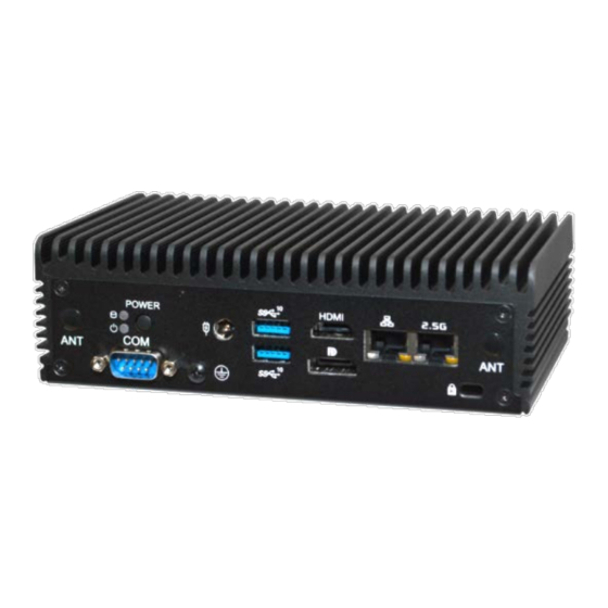
Page 10: Front Panel
eIVP-CFS-AI-D0000 AI Box 1.5 Front Panel Description Audio (Mic-in, Line-out) 2 x USB 3.2 Gen2 Ports (Type C, supports DP1.4 display output) USB 3.2 Gen2 (Type A) USB 2.0 (Type A) 1.1 Rear Panel Description Description COM Port RJ-45 (2.5G LAN)* Power Button DC-IN 2 x USB 3.2 Gen2 (Type A) - Page 11 eIVP-CFS-AI-D0000 AI Box Activity / Link LED Speed LED Description Description Status Status 1G/2.5G LAN 1G LAN 2.5G LAN No Link 10Mbps connection 10Mbps connection Blinking Data Activity Orange 100Mbps connection 100Mbps /1Gbps connection Link Green 1Gbps connection 2.5Gbps connection...
-
Page 12: Hardware Installation
eIVP-CFS-AI-D0000 AI Box Chapter 2. Hardware Installation 2.1 How to Remove the Bottom Case Remove the four screws on the bottom case. Then lift up and remove the bottom panel. -
Page 13: How To Install The Wifi Module
eIVP-CFS-AI-D0000 AI Box 2.2 How to Install the WiFi Module 1. Locate the WiFi Module slot on the motherboard. 2. Carefully insert the WiFi Module into the slot. 3. Tighten the screw to secure the WiFi Module to the motherboard. -
Page 14: How To Remove The M.2 Ssd And The Bracket
eIVP-CFS-AI-D0000 AI Box 2.3 How to Remove the M.2 SSD and the Bracket 1. Release the screw and carefully remove the M.2 SSD. 2. Release the screw and remove the bracket from the motherboard. -
Page 15: How To Install The M.2 Ssd
eIVP-CFS-AI-D0000 AI Box 2.4 How to Install the M.2 SSD 1. Locate the M.2 slot on the motherboard. 2. Carefully insert the M.2 SSD into the slot. Tighten the screw to secure the M.2 SSD to the motherboard. -
Page 16: How To Install The 2.5-Inch Hard Drive
eIVP-CFS-AI-D0000 AI Box 2.5 How to Install the 2.5-inch Hard Drive Remove the four screws on the bottom case. Then lift up and remove the bottom panel. Attach the HDD cage to the bottom panel and secure it using the four screws. Connect the SATA Data and Power Cable to the HDD. - Page 17 eIVP-CFS-AI-D0000 AI Box Connect the SATA Cable to the connector. Then reinstall the bottom panel.
-
Page 18: How To Install The Memory Modules (Ddr4)
eIVP-CFS-AI-D0000 AI Box 2.6 How to Install the Memory Modules (DDR4) Carefully insert the SO-DIMM memory modules into the slot at a 30-degree angle. Push down until the modules snap into place. Note: The system requires DDR4 SO-DIMM. For dual channel configuration, you always need to install identical (the same brand, speed, size and chip-type) DDR4 SO-DIMM pairs. -
Page 19: Motherboard
eIVP-CFS-AI-D0000 AI Box Chapter 3. Motherboard 3.1 Motherboard Layout No. Description Description M.2 Key-M Socket (M2_M1) Clear CMOS Header (CLRCMOS1) M.2 Key-E Socket (M2_E1) SATA3 Port (SATA3_0) USB2.0 Connector (USB2_7_8) SIO_AT1 COM Port Header (RS232) System Panel Header (PANEL1) Back Side Power Button (PWR_BTN1 Battery Connector (BAT1) FAN Connector (FAN1) -
Page 20: Jumpers Setup
eIVP-CFS-AI-D0000 AI Box 3.2 Jumpers Setup The illustration shows how jumpers are setup. When the jumper cap is placed on pins, the jumper is “Short”. If no jumper cap is placed on pins, the jumper is “Open”. The illustration shows a 3-pin jumper whose pin1 and pin2 are “Short”... -
Page 21: Onboard Headers And Connectors
eIVP-CFS-AI-D0000 AI Box 3.3 Onboard Headers and Connectors Please note that the onboard headers and connectors are NOT jumpers. Do NOT place jumper caps over these headers and connectors, otherwise, it will cause permanent damage to the motherboard. SATA3 Connector USB 2.0 Connector (SATA3_0: see p.14, No. - Page 22 eIVP-CFS-AI-D0000 AI Box Note: Connect the power switch, reset switch and system status indicator on the chassis to this header according to the pin assignments below. Note the positive and negative pins before connecting the cables. PWRBTN (Power Switch): Connect to the power switch on the chassis front panel. You may configure the way to turn off your system using the power switch.
-
Page 23: Installation Of Rom Socket
eIVP-CFS-AI-D0000 AI Box 3.4 Installation of ROM Socket * Do not apply force to the actuator cover after IC inserted. * Do not apply force to actuator cover when it is opening over 120 degree, otherwise, the actuator cover may be broken. * The yellow dot (Pin1) on the ROM must be installed at pin1 position of the socket. -
Page 24: Expansion Slot (M.2 Slots)
eIVP-CFS-AI-D0000 AI Box 3.5 Expansion Slot (M.2 Slots) There are 2 M.2 slots on this motherboard. M.2 for SSD: 1 x M.2 (KEY M, 2242/2260/2280) with PCIe Gen4 x4 and SATA3 for SSD. * M.2 Key M 2280(Supported by bracket) M.2 for Wi-Fi: 1 x M.2 (Key E, 2230) with PCIe x1, USB 2.0 and CNVi for Wireless. -
Page 25: Uefi Setup Utility
eIVP-CFS-AI-D0000 AI Box Chapter 4. UEFI Setup Utility 4.1 Introduction This section explains how to use the UEFI SETUP UTILITY to configure your system. The UEFI chip on the motherboard stores the UEFI SETUP UTILITY. You may run the UEFI SETUP UTILITY when you start up the computer. -
Page 26: Navigation Keys
eIVP-CFS-AI-D0000 AI Box Navigation Keys 4.1.2 Please check the following table for the function description of each navigation key. -
Page 27: Main Screen
eIVP-CFS-AI-D0000 AI Box 4.2 Main Screen When you enter the UEFI SETUP UTILITY, the Main screen will appear and display the system overview. -
Page 28: Advanced Screen
eIVP-CFS-AI-D0000 AI Box 4.3 Advanced Screen In this section, you may set the configurations for the following items: CPU Configuration, Chipset Configuration, Storage Configuration, Super IO Configuration, ACPI Configuration, USB Configuration, Trusted Computing, MCTP Configuration and Serial Port Console Redirection. Setting wrong values in this section may cause the system to malfunction. -
Page 29: Cpu Configuration
eIVP-CFS-AI-D0000 AI Box CPU Configuration 4.3.1 Cool ‘n‘ Quiet Use this item to enable or disable AMD’s Cool ‘n’ QuietTM technology. The default value is [Enabled]. Configuration options: [Enabled] and [Disabled]. If you install Windows® OS and want to enable this function, please set this item to [Enabled]. Please note that enabling this function may reduce CPU voltage and memory frequency, and lead to system stability or compatibility issue with some memory modules or power supplies. -
Page 30: Chipset Configuration
eIVP-CFS-AI-D0000 AI Box Chipset Configuration 4.3.2 Share Memory Configure the size of memory that is allocated to the integrated graphics processor when the system boots up. Onboard HD Audio Select [Enabled] or [Disabled] for the onboard HD Audio feature. Verb Table Select The default value is [Combo Jack]. -
Page 31: Storage Configuration
eIVP-CFS-AI-D0000 AI Box Storage Configuration 4.3.3 SATA Controller(s) Use this item to enable or disable the SATA Controller feature. SATA Mode Selection Use this to select SATA mode. The default value is [AHCI Mode]. Warning: AHCI (Advanced Host Controller Interface) supports NCQ and other new features that will improve SATA disk performance but IDE mode does not have these advantages. -
Page 32: Super Io Configuration
eIVP-CFS-AI-D0000 AI Box Super IO Configuration 4.3.4 COM1 Configuration Use this to set parameters of COM1. Type Select Use this to select COM1 port type: [RS232], [RS422] or [RS485]. WDT Timeout Reset Use this to set the Watch Dog Timer. -
Page 33: Acpi Configuration
eIVP-CFS-AI-D0000 AI Box ACPI Configuration 4.3.5 Suspend to RAM Use this item to select whether to auto-detect or disable the Suspend-to- RAM feature. Select [Auto] will enable this feature if the OS supports it. Onboard LAN Power On Use this item to enable or disable onboard LAN to turn on the system from the power- soft-off mode. -
Page 34: Usb Configuration
eIVP-CFS-AI-D0000 AI Box USB Configuration 4.3.6 Legacy USB Support Use this option to select legacy support for USB devices. There are two configuration options: [Enabled] and [UEFI Setup Only]. The default value is [Enabled]. Please refer to below descriptions for the details of these two options: [Enabled] - Enables support for legacy USB. -
Page 35: Trusted Computing
eIVP-CFS-AI-D0000 AI Box Trusted Computing 4.3.7 Security Device Support Enable or disable BIOS support for security device. -
Page 36: Hardware Health Event Monitoring Screen
eIVP-CFS-AI-D0000 AI Box 4.4 Hardware Health Event Monitoring Screen In this section, it allows you to monitor the status of the hardware on your system, including the parameters of the CPU temperature, motherboard temperature, CPU fan speed, chassis fan speed, and the critical voltage. CPU_FAN1 Setting This allows you to set CPU_FAN1’s speed. -
Page 37: Security Screen
eIVP-CFS-AI-D0000 AI Box 4.5 Security Screen In this section, you may set, change or clear the supervisor/user password for the system. Supervisor Password Set or change the password for the administrator account. Only the administrator has authority to change the settings in the UEFI Setup Utility. Leave it blank and press enter to remove the password. -
Page 38: Boot Screen
eIVP-CFS-AI-D0000 AI Box 4.6 Boot Screen In this section, it will display the available devices on your system for you to configure the boot settings and the boot priority. English Boot From Onboard LAN Use this item to enable or disable the Boot From Onboard LAN feature. Setup Prompt Timeout This shows the number of seconds to wait for setup activation key. - Page 39 eIVP-CFS-AI-D0000 AI Box CSM (Compatibility Support Module) Enable to launch the Compatibility Support Module. Please do not disable unless you’re running a WHCK test. If you are using Windows 8.1 64-bit and all of your devices support UEFI, you may also disable CSM for faster boot speed. Launch PXE OpROM Policy Select UEFI only to run those that support UEFI option ROM only.
-
Page 40: Exit Screen
eIVP-CFS-AI-D0000 AI Box 4.7 Exit Screen Save Changes and Exit When you select this option, it will pop-out the following message, “Save configuration changes and exit setup?” Select [OK] to save the changes and exit the UEFI SETUP UTILITY. Discard Changes and Exit When you select this option, it will pop-out the following message, “Discard changes and exit setup?”... - Page 41 FAX: +81 3 5820-1018 sales@everfocus.com www.everfocus.co.jp info@everfocus.co.jp Ihr EverFocus Produkt wurde entwickelt Your EverFocus product is designed and und hergestellt mit qualitativ manufactured with high quality materials hochwertigen Materialien und and components which can be recycled Komponenten, die recycelt und wieder and reused.