Table of Contents
Advertisement
,
CAUTION: TO REDUCE THE RISK OF ELECTRIC SHOCK, DO NOT
REMOVE COVER (OR BACK). NO USE-SERVICEABLE PARTS
INSIDE. REFER SERVICING TO QUALIFIED SERVICE PERSONNEL.
The lightning flash with arrowhead symbol, within an equilateral triangle, is
intended to alert the user to the presence of uninsulated "dangerous voltage"
within the product's enclosure that may be of sufficient magnitude to
constitute a risk of electric to persons.
The exclamation point within an equilateral triangle is intended to alert the
user to the presence of important operating and maintenance (servicing)
instructions in the literature accompanying the appliance.
WARNING: TO REDUCE THE RISK OF FIRE OR ELECTRIC SHOCK,
DO NOT EXPOSE THIS APPLIANCE TO RAIN OF MOISTURE.
POWER SUPPLY:
Connect the supplied adaptor to the side of the unit in the slot marked "DC 5V IN". Plug
the two-prong end of the power cord into an AC outlet or the cigarette lighter socket of
the vehicle. If you have difficulty inserting the plug, turn it over and reinsert it. If the unit is
not used for a long time, disconnect the plug from the socket.
NOTE:
Before plugging the power cord into an AC outlet or a cigarette lighter socket of vehicle,
make sure that all the connections have been made.
CAUTION: To reduce the risk of electric shock, do not perform any servicing other than
that contained in the operation instructions unless you are qualified to do so.
CAUTION: If you are not experienced in working with electrical wiring, you should
seriously consider having your reversing camera installed by a professional.
Refer to service manual for servicing instructions. To reduce the risk of fire or electric
shock, do not expose this apparatus to rain or moisture.
Important Safety
Instructions
1
Advertisement
Table of Contents

Related Manuals for Nextar I4-BC


Summary of Contents for Nextar I4-BC
-
Page 1: Important Safety Instructions
, CAUTION: TO REDUCE THE RISK OF ELECTRIC SHOCK, DO NOT REMOVE COVER (OR BACK). NO USE-SERVICEABLE PARTS INSIDE. REFER SERVICING TO QUALIFIED SERVICE PERSONNEL. The lightning flash with arrowhead symbol, within an equilateral triangle, is intended to alert the user to the presence of uninsulated “dangerous voltage” within the product’s enclosure that may be of sufficient magnitude to constitute a risk of electric to persons. - Page 2 15) Apparatus shall not be exposed to dripping or splashing and no objects filled with liquids, such as vases, shall be placed on the apparatus. To prevent the GPS from being damaged, be sure to keep the GPS out of direct sunlight or heat.
- Page 3 UL has only tested for fire, shock or casualty hazards as outlined in UL’s Standard(s) for Safety [Note-Consider referencing specific UL standard]. UL Certification does not cover the performance or reliability of the GPS hardware and GPS operating software.
- Page 4 Important Safety Instructions Note: This equipment has been tested and found to comply with limits for Class B digital device, pursuant to part 15 of the FCC Rules. These limits are designed to provide reasonable protection against harmful interference in a residential installation. This equipment generates, uses and can radiate radio frequency energy and, if not installed and used in accordance with the instructions, may cause harmful interference to radio or television reception, which can be determined by turning the equipment off and on, the...
-
Page 5: Accessories
Accessories List ITEM NOTE Accessories and their parts numbers are subject to modification without prior notice due to improvements. Accessories NAME Instruction Manual Reversing Camera (With fitting parts) AC Adaptor Car Adaptor Mounting Bracket USB Cable Mounting Cradle Stylus Dashboard Mount Disk Pouch... -
Page 6: Table Of Contents
Contents Important Safety Instructions Accessories View of Main Unit System Connections Power Supply Preparation General Setup Playing Music Photo Viewer GPS Unit Installation Reversing Camera Troubleshooting Specifications …………………………………….………..1 ……………………………….………..…...5 ……………………………….…………...7 ……………………………….……….…...8 …………………………….……….….….10 ……………………………….……………12 …………………………….………………16 ……………………………….……………18 ……………………………….…………...20 ……………………………….…………...21 ……………………………….…………...26 ………………………………………….…28... -
Page 7: View Of Main Unit
POWER Button Press the power button for longer time to enter or exit the standby mode. Card Slot Insert the SD card into the slot. Headphone Jack Used to connect headphones for private listening. When the headphones are connected to this jack, the speaker will be turned off automatically. DC 5V Input Jack Used to connect to the supplied adaptor. -
Page 8: System Connections
System Connections Always ensure that the unit and any other external device connected to the unit are switched off and unplugged from the power supply before you attempt to connect the unit to any external device. Connecting to PC The unit is designed with a USB port which allows you to connect the unit to a PC for map updating. - Page 9 System Connections Inserting SD Card The unit is designed with an SD Card slot which allows you to insert an SD card into the unit as shown below: To remove the card, gently press the card in with your fingernail. The card unlocks and protrudes slightly.
-
Page 10: Power Supply Preparation
Attention Place the unit in a proper position for viewing. Disconnect the unit from the Car Adaptor when starting the vehicle. Your portable GPS unit comes with a built-in rechargeable battery. Please see details in the following segment. -
Page 11: Charging The Battery Pack
Working conditions and precautions for the rechargeable battery Battery should only be used and charged when temperatures are between 32°-100°F. Maintain well-ventilated conditions around the product to avoid overheating. Don’t put the product on a bed, sofa or anything that may block ventilation to the product. When the battery is weak, an indication menu will appear on the LCD screen and the unit will power off automatically after a while. -
Page 12: General Setup
General Setup System Main Menu When in navigation mode, tap button in the Menu screen. A confirmation message appears asking if you want to exit the program now, as shown below. In the confirmation screen, tap and the system main menu appears. In the main menu, there are four items for selecting. - Page 13 Language in the settings menu to enter Language settings menu for language selecting, as shown below: Tap the buttons to select language. Then tap cancel. Backlight in the settings menu to enter Backlight settings menu for backlight adjusting, as shown below: Tap the buttons to adjust the backlight level.
- Page 14 General Setup Date & Time in the settings menu to enter Date & Time settings menu for changing to the current time zone, as shown below: Tap the buttons to select the proper Time Zone. Tap the Date group to change the corresponding date and tap the group to change the corresponding time.
- Page 15 General Setup Screen in the settings menu, the screen will display as below: This item is used to calibrate the sensitivity of the touch screen. Tap the center of “+” as it moves around the screen. If you touch the center of “+” every time, it will disappear after having moved through a cycle (center→top left corner→bottom left corner→bottom right corner→top right corner).
-
Page 16: Playing Music
Playing Music The unit is designed with an SD card slot. You can insert an SD card with MP3 and WMA files. It supports MP3 and WMA files playback. Note: Do not store MP3, WWA files in the Flash storage, for the flash storage is used to store map data, any attempt to open the Flash storage may result in missing and lost map data. - Page 17 When you open the play list, the system will look for MP3 files on its SD memory card and create a play list automatically. If the play list consists of more than one screen, tap the up arrow for the previous page and the down arrow In the play list, double tap the songs to start playback.
-
Page 18: Photo Viewer
Photo Viewer The unit is designed with SD card slot. You can insert the SD card with JPG files. It supports JPG format files playback. Note: Do not store JPG format files in the Flash storage, for the flash storage is used to store map data, any attempt to open the Flash storage may result in missing and lost map data. - Page 19 In the pictures list, double tap a picture to play it on screen, as shown below. On the playback screen, the Photo Viewer has following playback features: to rotate the picture. to go back to the previous picture; tap to zoom the picture in or out. to play the picture in full-screen mode;...
-
Page 20: Gps Unit Installation
There is one wireless receiver in the mount cradle. It can receive the signal sent by the emitter in the Reversing Camera and input these signals into the GPS unit by the combination of the unit and the cradle (see right figure). -
Page 21: Reversing Camera
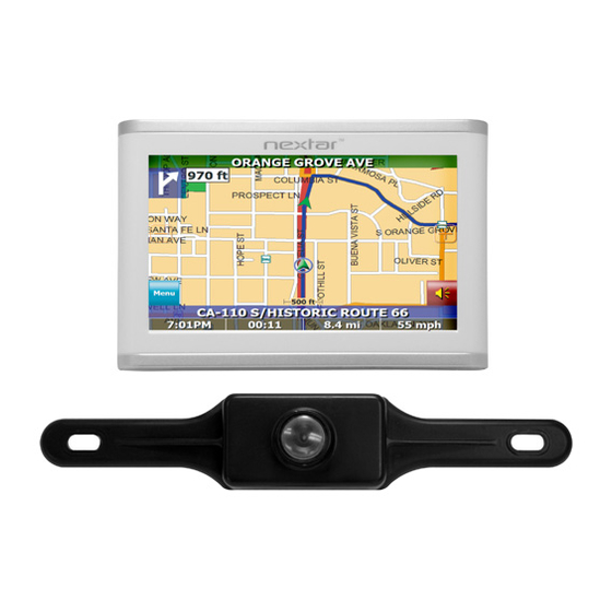
INTRODUCTION TO YOUR REVERSING CAMERA: Your navigation system comes equip with a wireless reversing camera. Upon placing the vehicle in reverse, the reversing camera engages and an image of behind your vehicle is displayed on the 4.3 inch LCD screen. This view will aid you in backing up your vehicle as well as parking. - Page 22 Reversing Camera CAUTION: PLEASE READ the test light/ multimeter’s instruction manual before use. The test light/multimeter’s negative lead should be grounded (i.e., touching the metal of the vehicle) and the positive lead should be used for the testing of which wire is positive or negative. The positive wire will cause the test light/mulitmeter to signal that power is running through the wire.
- Page 23 into your vehicle directly adjacent to your license plate, you will need to drill a hole in to your vehicle adjacent to your license plate with a power drill or some other means (SEE CAUTION BELOW). Once a hole is found or made, then take the reversing camera power wire and insert into the hole.
- Page 24 Reversing Camera If you are using the lower portion (see picture B below) of the license plate: iii. STEP THREE: Accessing the Power Source. You must now determine a route to run your reversing camera’s wiring to the power source (the reverse taillight power wiring). Follow pictures C below for a sample route. Depending on the type of vehicle, the below pictures may not provide an exact replica of your vehicle set up.
- Page 25 Seventh, if the rearview displayed on your LCD screen is upside down, you must exit the vehicle, detach the reversing camera from the license plate, turn it clockwise or counterclockwise (180 degrees), and affix the camera to the license plate. For further troubleshooting suggestions, please see the back pages of the I4-BC manual.
-
Page 26: Troubleshooting
Troubleshooting Take steps described in the tables below to solve simple problems before contacting customer service. If you suspect something wrong with the unit, immediately turn the power off and disconnect the power connector from the unit. Never try to repair the unit yourself because it is dangerous to do so. - Page 27 PROBLEM The unit can receive signals now but can’t then; signals received are not stable. Other possibilities: Static or other external interference may cause the unit to function abnormally. In order to recover normal status, please unplug the power supply cord and then plug it into the outlet again to reset the player.