Siemens SITRANS LG240 Operating Instructions Manual
Guided wave radar profibus pa polished rod probe
Hide thumbs
Also See for SITRANS LG240:
- Operating instructions manual (88 pages) ,
- Operating instructions manual (80 pages)

Related Manuals for Siemens SITRANS LG240


Summary of Contents for Siemens SITRANS LG240
- Page 1 Guided Wave Radar SITRANS LG240 Profibus PA Polished rod probe Operating Instructions • 01/2020...
- Page 2 SITRANS LG240 - Operating Instructions PBD-51041044...
-
Page 3: Table Of Contents
Saving the parameterisation data ................... 49 Set up with other systems ....................50 DD adjustment programs ....................50 Diagnostics and servicing ....................51 Maintenance ........................51 Diagnosis memory ......................51 Status messages ......................52 PBD-51041044 SITRANS LG240 - Operating Instructions... - Page 4 11.3 Dimensions ........................78 11.4 Trademark ........................83 Safety instructions for Ex areas Take note of the Ex specific safety instructions for Ex applications. These instructions are attached as documents to each instrument with Ex approval and are part of the operating instructions. Editing status: 2020-01-24 SITRANS LG240 - Operating Instructions PBD-51041044...
-
Page 5: About This Document
The dot set in front indicates a list with no implied sequence. Sequence of actions Numbers set in front indicate successive steps in a procedure. Battery disposal This symbol indicates special information about the disposal of bat- teries and accumulators. PBD-51041044 SITRANS LG240 - Operating Instructions... -
Page 6: For Your Safety
During work on and with the device, the required personal protective equipment must always be worn. Appropriate use SITRANS LG240 is a sensor for continuous level measurement. You can find detailed information about the area of application in chapter "Product description". Operational reliability is ensured only if the instrument is properly used according to the specifications in the operating instructions manual as well as possible supplementary instructions. -
Page 7: Eu Conformity
English language. Installations in the US shall comply with the relevant requirements of the National Electrical Code (ANSI/NFPA 70). Installations in Canada shall comply with the relevant requirements of the Canadian Electrical Code. PBD-51041044 SITRANS LG240 - Operating Instructions... -
Page 8: Product Description
Sensor SITRANS LG240 • Optional accessory The further scope of delivery encompasses: • Documentation – Operating instructions SITRANS LG240 – Instructions for optional instrument features – Ex-specific "Safety instructions" (with Ex versions) – If necessary, further certificates Information: Optional instrument features are also described in this operating instructions manual. -
Page 9: Principle Of Operation
14 Hardware and software version Principle of operation Application area The SITRANS LG240 is a level sensor with polished rod probe for continuous level or interface measurement, particularly suitable for applications in the food processing and pharmaceutical industry. Optionally an autoclaved version with separable housing is available. - Page 10 Distance to the interface d2 Distance to the level TS Thickness of the upper medium (d1 - d2) h1 Height - Interface h2 Height - Level L1 Lower medium L2 Upper medium L3 Gas phase SITRANS LG240 - Operating Instructions PBD-51041044...
-
Page 11: Packaging, Transport And Storage
Ascertained transit damage or con- cealed defects must be appropriately dealt with. Storage Up to the time of installation, the packages must be left closed and stored according to the orientation and storage markings on the outside. PBD-51041044 SITRANS LG240 - Operating Instructions... -
Page 12: Accessories
• Rod segments: 450 … 480 mm (17.72 … 18.9 in) • End segment: 26 … 480 mm (1.02 … 18.9 in) Centering If you mount the SITRANS LG240 in a bypass tube or standpipe, you have to avoid contact to the bypass tube by using a spacer at the probe end. SITRANS LG240 - Operating Instructions PBD-51041044... -
Page 13: Mounting
Hence make sure before mounting that all parts of the instrument ex- posed to the process are suitable for the existing process conditions. These are mainly: • Active measuring component • Process fitting • Process seal PBD-51041044 SITRANS LG240 - Operating Instructions... -
Page 14: Mounting Instructions
• Abrasion and mechanical influences Mounting instructions Installation position Mount SITRANS LG240 in such a way that the distance to vessel installations or to the vessel wall is at least 300 mm (12 in). In non- metallic vessels, the distance to the vessel wall should be at least 500 mm (19.7 in). During operation, the probe must not touch any installations or the vessel wall. - Page 15 In such cases, always carry out a false signal suppression after mounting. You can find further information under "Setup procedure". ≤ 150 mm ( 5.91") DN25 ... DN150 > DN150 ... DN200 ≤ 100 mm ( 3.94") Fig. 6: Mounting socket When welding the socket, make sure that the socket is flush with the vessel top. PBD-51041044 SITRANS LG240 - Operating Instructions...
- Page 16 Keep in mind that a min. distance must be maintained below the refer- ence plane and possibly also at the end of the probe - measurement in these areas is not possible (dead zone). The length of the cable can be used all the way to the end only when measuring conductive SITRANS LG240 - Operating Instructions PBD-51041044...
- Page 17 Screw the enclosed lid with slotted nut onto the instrument side of the process fitting and tighten the nut with a torque of 20 Nm. Make sure that no liquid or contamination penetrates into the housing or the process side. After autoclaving, screw the lid off again and place the housing verti- cally on the side of the process fitting. Tighten the slotted nut with a torque of 20 Nm. PBD-51041044 SITRANS LG240 - Operating Instructions...
- Page 18 DIN DN25 DN32 DN40 / 1" 1 1/2" ø 50,5 DIN DN50 / 2" ø 64 DIN DN65 / 3" ø 91 Fig. 9: Autoclaved version Groove nut 2 Process fitting Cover with groove nut SITRANS LG240 - Operating Instructions PBD-51041044...
-
Page 19: Connecting To Power Supply
Note: Prior to setup you have to replace these protective caps with ap- proved cable glands or close the openings with suitable blind plugs. PBD-51041044 SITRANS LG240 - Operating Instructions... -
Page 20: Connecting
5. Insert the cable into the sensor through the cable entry Fig. 10: Connection steps 5 and 6 Single chamber housing Double chamber housing 6. Insert the wire ends into the terminals according to the wiring plan SITRANS LG240 - Operating Instructions PBD-51041044... -
Page 21: Wiring Plan, Single Chamber Housing
Selection switch for instrument address For external display and adjustment unit Ground terminal for connection of the cable screening Wiring plan, double chamber housing The following illustration applies to the non-Ex, Ex-ia and Ex-d ver- sion. PBD-51041044 SITRANS LG240 - Operating Instructions... -
Page 22: Set Instrument Address
Profibus PA network. Then the address must be changed to integrate additional instruments. The address setting is carried out either via: • The address selection switch in the electronics compartment of the instrument (address setting via hardware) • The display and adjustment module (address setting via software) • PACTware/DTM (address setting via software) SITRANS LG240 - Operating Instructions PBD-51041044... -
Page 23: Switch-On Phase
PC • Status byte goes to fault value Then the actual measured value is output to the signal cable. The value takes into account settings that have already been carried out, e.g. default setting. PBD-51041044 SITRANS LG240 - Operating Instructions... -
Page 24: Set Up With The Display And Adjustment Module
Fig. 15: Insertion of the display and adjustment module with single chamber housing Note: If you intend to retrofit the instrument with a display and adjustment module for continuous measured value indication, a higher lid with an inspection glass is required. SITRANS LG240 - Operating Instructions PBD-51041044... -
Page 25: Adjustment System
[OK] will not be saved. Switch-on phase After switching on, the SITRANS LG240 carries out a short self-test where the device software is checked. The output signal transmits a fault signal during the switch-on phase. The following information is displayed on the display and adjustment module during the startup procedure: •... -
Page 26: Parameter Adjustment - Quick Setup
False signal suppression You can find the description of the individual menu items in the follow- ing chapter "Parameter adjustment - Extended adjustment". Parameter adjustment - Extended adjustment For technically demanding measuring points, you can carry out extended settings in "Extended adjustment". Main menu The main menu is divided into five sections with the following func- tions: SITRANS LG240 - Operating Instructions PBD-51041044... - Page 27 The address selection switch in the electronics compartment of the instrument (address setting via hardware) • The display and adjustment module (address setting via software) • PACTware/DTM (address setting via software) Hardware addressing Hardware addressing is effective if an address less than 126 is set with the address selection switches on the electronics module of SITRANS LG240. In such case, software addressing has no effect - only the set hardware address applies. PBD-51041044 SITRANS LG240 - Operating Instructions...
- Page 28 In this menu item you can enter the probe length or have the length determined automatically by the sensor system. When choosing "Yes", then the probe length will be determined automatically. When choosing "No", you can enter the probe length manually. SITRANS LG240 - Operating Instructions PBD-51041044...
- Page 29 "Application". In this menu item you can enter if there is a superimposed gas phase in your application. Only set the function to "Yes", if the gas phase is permanently pre- sent. PBD-51041044 SITRANS LG240 - Operating Instructions...
- Page 30 Min. adjustment level In this menu item you can enter the min. adjustment for the level. With interface measurement this is the minimum total level. Adjust the requested percentage value with [+] and store with [OK]. SITRANS LG240 - Operating Instructions PBD-51041044...
- Page 31 Enter the respective distance value in m for the interface correspond- ing to the percentage value of the interface. False signal suppression The following circumstances cause interfering reflections and can influence the measurement: • High mounting sockets • Vessel internals such as struts PBD-51041044 SITRANS LG240 - Operating Instructions...
- Page 32 Corresponding linearisation curves are preprogrammed for these vessels. They represent the correlation between the level percentage and vessel volume. SITRANS LG240 - Operating Instructions PBD-51041044...
- Page 33 If the socket is lower than the up- per edge of the vessel, this value can also be negative. Fig. 17: Vessel height and socket correction value D Vessel height +h Positive socket correction value -h Negative socket correction value PBD-51041044 SITRANS LG240 - Operating Instructions...
- Page 34 AI FB1 - damping To damp process-dependent measured value fluctuations, you can set a time of 0 … 999 s in this menu item. The damping applies to the level and interface measurement. The default setting is a damping of 0 s. SITRANS LG240 - Operating Instructions PBD-51041044...
- Page 35 This menu item enables the setting of the requested national lan- guage. In delivery status, the sensor is set to English. Displayed value 1 In this menu item, you define the indication of the measured value on the display. You can display two different measured values. In this menu item, you define measured value 1. The default setting for the displayed value 1 is "Filling height Level". PBD-51041044 SITRANS LG240 - Operating Instructions...
- Page 36 The two values are displayed in the menu item "Peak values, distance". If you have selected interface measurement under the menu item "Setup - Application", the peak values of the interface measurement are displayed in addition to the peak values of the level measurement. SITRANS LG240 - Operating Instructions PBD-51041044...
- Page 37 This menu item displays the peak values of the electronics tempera- ture as well as the dielectric constant. In another window you can carry out a reset of the two peak values separately. PBD-51041044 SITRANS LG240 - Operating Instructions...
- Page 38 With this, you can detect signal changes over the operating time. With the adjustment software PACTware and the PC, the high-resolution echo curve can be displayed and used to compare the echo curve of the setup with the actual echo curve. SITRANS LG240 - Operating Instructions PBD-51041044...
- Page 39 Delivery status: Restores the parameter settings at the time of ship- ment from the factory, incl. order-specific settings. Any stored false signal suppression or user-programmed linearisation curve, as well as the measured value memory, are deleted. Basic settings: Resetting of the parameter settings incl. special parameters to the default values (presettings) of the respective instru- PBD-51041044 SITRANS LG240 - Operating Instructions...
- Page 40 Linearisation - Vessel height Probe length AI FB1 Tag Descriptor AI FB1 Channel Primary Value (lin. percent level) AI FB1 scaling PV Scale (min.) AI FB1 scaling PV Scale (max.) 100 % AI FB1 Lin. Type Linear AI FB1 Out Scale Unit AI FB1 Out Scale Decimal Point #.## SITRANS LG240 - Operating Instructions PBD-51041044...
- Page 41 Device memory - Measured value memory - Start with meas- Not active ured value Device memory - Measured value memory - Stop with meas- Not active ured value Device memory - Measured value memory - Stop recording Not active when memory is full PBD-51041044 SITRANS LG240 - Operating Instructions...
- Page 42 AI FB3 Out Scale Decimal Point #.## AI FB3 Out Scale (min.) AI FB3 Out Scale (max.) 100 % AI FB3 PV FTime AI FB3 Hi Hi Limit 3.402823E+38 % AI FB3 Hi Limit 3.402823E+38 % AI FB3 Lo Lo Limit -3.402823E+38 % SITRANS LG240 - Operating Instructions PBD-51041044...
- Page 43 TAG-no. this sensor had. Tip: We recommend to save the instrument adjustments. In case of an electronics exchange the saved parameter adjustment data relieve this process. PBD-51041044 SITRANS LG240 - Operating Instructions...
- Page 44 PC. Profibus Ident Number In this menu item, the Profibus ident number of your sensor is dis- played. Sensor characteristics In this menu item, the features of the sensor such as approval, pro- cess fitting, seal, measuring range, electronics, housing and others are displayed. Example for displayed sensor features. SITRANS LG240 - Operating Instructions PBD-51041044...
-
Page 45: Saving The Parameterisation Data
The following steps for the quick setup can be reached also in the "Extended adjustment". • Instrument address • Measurement loop name • Medium type (optional) • Application • Max. adjustment • Min. adjustment • False signal suppression You can find the description of the individual menu items in the follow- ing chapter "Parameter adjustment - Extended adjustment". PBD-51041044 SITRANS LG240 - Operating Instructions... -
Page 46: Setup With Pactware
A description of the update procedure is also available in the Internet. The further setup steps are described in the online help of PACTware and the DTMs. SITRANS LG240 - Operating Instructions PBD-51041044... -
Page 47: Set Up With The Quick Setup
The quick setup is another option for parameter adjustment of the sensor. It allows fast, convenient adjustment of the most important parameters to adapt the sensor quickly to standard applications. To use it, select the function "Quick setup" in the start screen. PBD-51041044 SITRANS LG240 - Operating Instructions... - Page 48 Extended adjustment Maintenance Quick setup With quick setup you can carry out the parameter adjustment of SITRANS LG240 for your application in just a few simple steps. The assistant-driven adjustment includes the basic settings for simple, reliable setup and commissioning. Information: If the function is inactive, then possibly no instrument is connected.
-
Page 49: Saving The Parameterisation Data
Saving the parameterisation data We recommend documenting or saving the parameterisation data via PACTware. That way the data are available for multiple use or service purposes. PBD-51041044 SITRANS LG240 - Operating Instructions... -
Page 50: Set Up With Other Systems
Set up with other systems DD adjustment programs Device descriptions as Enhanced Device Description (EDD) are available for DD adjustment programs such as, for example, AMS↑ and PDM. SITRANS LG240 - Operating Instructions PBD-51041044... -
Page 51: Diagnostics And Servicing
Up to 500 events are automatically stored with a time stamp in the sensor (non-deletable). Each entry contains date/time, event type, event description and value. Event types are for example: • Modification of a parameter • Switch-on and switch-off times • Status messages (according to NE 107) • Error messages (according to NE 107) The data are read out via a PC with PACTware/DTM or the control system with EDD. PBD-51041044 SITRANS LG240 - Operating Instructions... -
Page 52: Status Messages
Failure: Due to a malfunction in the instrument, a fault message is output. This status message is always active. It cannot be deactivated by the user. Function check: The instrument is being worked on, the measured value is temporarily invalid (for example during simulation). This status message is inactive by default. SITRANS LG240 - Operating Instructions PBD-51041044... - Page 53 Disconnect operating voltage briefly munication Communication Send instrument for repair error F125 Temperature of the electronics in the Check ambient temperature Bit 7 non-specified range Impermissible Insulate electronics electronics tem- Use instrument with higher temper- perature ature range PBD-51041044 SITRANS LG240 - Operating Instructions...
- Page 54 S601 Level echo in the close range not Reduce level Bit 24 available Overfilling 100 % adjustment: Increase value Check mounting socket Remove possible interfering signals in the close range Use coaxial probe SITRANS LG240 - Operating Instructions PBD-51041044...
-
Page 55: Rectify Faults
The operator of the system is responsible for taking suitable meas- tion occurs ures to rectify faults. The first measures are: Fault rectification • Evaluation of fault messages • Checking the output signal • Treatment of measurement errors PBD-51041044 SITRANS LG240 - Operating Instructions... - Page 56 A false signal suppression was not car- ried out Amplitude or position of a false signal Determine the reason for the changed has changed (e.g. buildup); false signal false signals, carry out false signal sup- time suppression no longer matches pression, e.g. with buildup SITRANS LG240 - Operating Instructions PBD-51041044...
- Page 57 Measured value remains re- Stored false signals in this position are Delete false signal suppression producible in one position larger than the level echo Carry out a new false signal suppression during emptying time PBD-51041044 SITRANS LG240 - Operating Instructions...
- Page 58 Amplitude or position of a false signal has Determine the reason for the changed false changed (e.g. condensation, buildup); false signals, carry out false signal suppression, signal suppression no longer matches ac- e.g. condensation time tual conditions SITRANS LG240 - Operating Instructions PBD-51041044...
- Page 59 Carry out false signal suppression or in- jumps sporadically the antenna crease false signal suppression in the close towards 100 % dur- range by editing ing emptying With bulk solids use radar sensor with purg- ing air connection or flexible antenna cover time PBD-51041044 SITRANS LG240 - Operating Instructions...
-
Page 60: Exchanging The Electronics Module
10. Caution: Remember that the polished rod of the food version is very sensitive to damage and scratching. Use special tools in order to avoid damag- ing the surface. 1. Loosen the rod by applying a fork spanner to the flat surfaces (SW 10), provide counterforce manually on the process fitting SITRANS LG240 - Operating Instructions PBD-51041044... -
Page 61: Exchanging The Seal
Such instruments must therefore be returned to the factory when a seal replacement is necessary. Three different seal sets are available. They contain the seals for the process fitting and the measuring rod. For segmented rods, several seals for the measuring rod are included. Exchange the seal whenever you loosen connection. • EPDM (Freudenberg 70, EPDM 291), -20 … +130 °C • FFKM (Kalrez 6221), -20 … +150 °C • FEPM (Vi 602 Extreme-ETP, COG), -10 … +150 °C PBD-51041044 SITRANS LG240 - Operating Instructions... - Page 62 2. Screw out the loosened measuring rod by hand 3. Push the enclosed new rod seal ring (9.25 x 1.78) onto the thread of the measuring rod. Fig. 24: Remove measuring rod Sealing ring (9.25 x 1.78) 4. Loosen process fitting with a suitable wrench. 5. Unscrew the process fitting manually from the sensor. 6. Remove the old process seal out of the process fitting. 7. Insert the attached new process seal ring (15.54 x 2.62) into the process fitting. SITRANS LG240 - Operating Instructions PBD-51041044...
-
Page 63: Software Update
11. Exert counterforce manually and tighten the rod on the flat sur- faces with a torque of max. 4.5 Nm (3.32 lbf ft). Information: Please maintain the specified torque so that the max. tensile strength of the connection remains. Software update The following components are required to update the sensor soft- ware: • Sensor • Voltage supply • PC with PACTware • Current sensor software as file PBD-51041044 SITRANS LG240 - Operating Instructions... -
Page 64: How To Proceed If A Repair Is Necessary
Instruments with approvals can be bound to certain software versions. Therefore make sure that the approval is still effective after a software update is carried out. You can find detailed information in the download area on our home- page: www.siemens.com/sitranslg. How to proceed if a repair is necessary If it is necessary to repair the instrument, please contact Siemens. You find the locations on "www.siemens.com/processautomation". SITRANS LG240 - Operating Instructions PBD-51041044... -
Page 65: Dismount
Pass the instrument directly on to a specialised recycling company and do not use the municipal collecting points. If you have no way to dispose of the old instrument properly, please contact us concerning return and disposal. PBD-51041044 SITRANS LG240 - Operating Instructions... -
Page 66: Supplement
DN 32 PN 40 Weight Ʋ Instrument weight (depending on approx. 0.8 … 8 kg (0.176 … 17.64 lbs) process fitting) Ʋ Rod: ø 8 mm (0.315 in), polished approx. 400 g/m (4.3 oz/ft) Probe length L (from seal surface) Ʋ Rod: ø 8 mm (0.315 in), polished up to 4 m (13.12 ft) - also possible for segmented rods Ʋ Trimming accuracy (rod) ±1 mm + 0.05 % of the rod length All wetted parts. SITRANS LG240 - Operating Instructions PBD-51041044... - Page 67 +860 … +1060 mbar/+86 … +106 kPa (+12.5 … +15.4 psig) Mounting, reference conditions Ʋ Min. distance to internal installations > 500 mm (19.69 in) Ʋ Vessel metallic, ø 1 m (3.281 ft), centric mounting, process fit- ting flush with the vessel ceiling Ʋ Medium Water/Oil (dielectric constant ~2.0) Ʋ Mounting Probe end does not touch the vessel bottom With interface measurement = 2.0 PBD-51041044 SITRANS LG240 - Operating Instructions...
- Page 68 Sensor parameter adjustment No gating out of false signals carried out Fig. 26: Measuring ranges - SITRANS LG240 Reference plane Probe length L Measuring range (default setting refers to the measuring range in water) Upper dead zone (see following diagrams - grey section)
- Page 69 0,08 m 0,2 m 0,04 m (3.15 (7.874 " " (1.575 ") Fig. 27: Deviation SITRANS LG240 in rod version in water Dead zone (no measurement possible in this area) Probe length 15 mm (0.591 " 2 mm (0.079 ") -2 mm (-0.079...
- Page 70 Vessel pressure relating to the flange see supplementary instructions manual "Flanges ac- nominal pressure stage cording to DIN-EN-ASME-JIS" Time span after a sudden measuring distance change by max. 0.5 m in liquid applications, max 2 m with bulk solids applications, until the output signal has taken for the first time 90 % of the final value (IEC 61298-2). SITRANS LG240 - Operating Instructions PBD-51041044...
- Page 71 Electromechanical data - version IP66/IP67 and IP66/IP68 (0.2 bar) Options of the cable entry Ʋ Cable entry M20 x 1.5; ½ NPT Ʋ Cable gland M20 x 1.5; ½ NPT (cable ø see below table) Ʋ Blind plug M20 x 1.5; ½ NPT Ʋ Closing cap ½ NPT PBD-51041044 SITRANS LG240 - Operating Instructions...
- Page 72 10.5 min/year Additional output parameter - Electronics temperature Range -40 … +85 °C (-40 … +185 °F) Resolution < 0.1 K Deviation ±3 K Output of the temperature values Ʋ Indication Via the display and adjustment module Ʋ Output Via the respective output signal SITRANS LG240 - Operating Instructions PBD-51041044...
-
Page 73: Communication Profibus Pa
Altitude above sea level Ʋ by default up to 2000 m (6562 ft) Ʋ with connected overvoltage protection up to 5000 m (16404 ft) Pollution degree Protection class 11.2 Communication Profibus PA Instrument master file The instrument master file (GSD) contains the characteristic data of the Profibus PA instrument. Galvanic separation between electronics and metal housing parts When used with fulfilled housing protection IEC 61010-1 PBD-51041044 SITRANS LG240 - Operating Instructions... - Page 74 Instrument ID GSD file name Siemens Instrument class in Siemens Profile-specific profile 3.02 SITRANS series LG 0x81B9 0x9702 SI0181B9.GSD PA139702.GSD Cyclical data traffic The master class 1 (e.g. PLC) cyclically reads out measured values from the sensor during opera- tion. The below block diagram below shows which data can be accessed by the PLC. SITRANS LG240 - Operating Instructions PBD-51041044...
- Page 75 Fig. 30: SITRANS LG240: Block diagram with AI FB 1 … AI FB 3 OUT values TB Transducer Block FB 1 … FB 3 Function Block Module of the PA sensors For the cyclic data traffic, SITRANS LG240 provides the following modules: • AI FB1 (OUT) – Out value of the AI FB1 after scaling •...
- Page 76 -10 -11 -12 -13 -14 -15 -16 -17 -18 -19 -20 -21 -22 -23 Sign Significant Significant Exponent Significant (Exponent - 127) Value = (-1) (1 + Significant) Fig. 32: Data format of the measured value SITRANS LG240 - Operating Instructions PBD-51041044...
- Page 77 0 x 8a good (non-cascade) - ac- Hi-Alarm tive advisory alarm - high limited 0 x 8d good (non-cascade) - ac- Lo-Lo-Alarm tive critical alarm - low limited 0 x 8e good (non-cascade) - ac- Hi-Hi-Alarm tive critical alarm - high limited PBD-51041044 SITRANS LG240 - Operating Instructions...
-
Page 78: Dimensions
½ NPT Fig. 34: Housing versions with protection rating IP66/IP68 (0.2 bar), (with integrated display and adjustment mod- ule the housing is 9 mm/0.35 in higher) Aluminium - single chamber Aluminium - double chamber SITRANS LG240 - Operating Instructions PBD-51041044... - Page 79 Fig. 35: Housing versions with protection rating IP66/IP68 (0.2 bar), (with integrated display and adjustment mod- ule the housing is 9 mm/0.35 in higher) Stainless steel single chamber (electropolished) Stainless steel single chamber (precision casting) Stainless steel double chamber housing (precision casting) PBD-51041044 SITRANS LG240 - Operating Instructions...
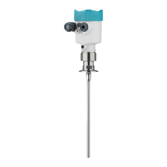
- Page 80 SITRANS LG240, rod version ø 8 mm (0.315 in), polished ø 8 mm (0.32") Fig. 36: SITRANS LG240, rod version ø 8 mm (0.315 in), polished Sensor length, see chapter "Technical data" SITRANS LG240 - Operating Instructions PBD-51041044...
- Page 81 ø 50,5 DIN DN50 / 2" ø 64 DIN DN65 / 3" ø 91 Fig. 37: SITRANS LG240, rod version ø 8 mm (0.315 in), polished - autoclaved version Compression nut Process fitting Cover lid PBD-51041044 SITRANS LG240 - Operating Instructions...
- Page 82 1 Version with threaded fitting 2 Version with flange connection A Basic extension rod with ø 8 mm (0.315 in) B Extension rod with ø 8 mm (0.315 in) C End rod with ø 8 mm (0.315 in) Length (order length) SITRANS LG240 - Operating Instructions PBD-51041044...
-
Page 83: Trademark
11.4 Trademark All the brands as well as trade and company names used are property of their lawful proprietor/ originator. PBD-51041044 SITRANS LG240 - Operating Instructions... - Page 84 Quick setup 26, 45 Factory calibration date 44 False signal suppression 31 Fault Read out info 44 – Rectification 55 Repair 64 Fault rectification 55 Replacement parts Functional principle 9 – Rod components 12 – Spacer 12 SITRANS LG240 - Operating Instructions PBD-51041044...
- Page 85 Scaling unit 34 Sensor characteristics 44 Sensor status 36 Simulation 38 Software addressing 23, 28 Special parameters 44 Status bytes PA output value 77 Telegram configuration 76 Type label 8 Type of medium 29 Units 28 PBD-51041044 SITRANS LG240 - Operating Instructions...
- Page 86 Notes SITRANS LG240 - Operating Instructions PBD-51041044...
- Page 87 Notes PBD-51041044 SITRANS LG240 - Operating Instructions...
- Page 88 For more information www.siemens.com/level www.siemens.com/weighing Siemens Canada Limited Subject to change without prior notice PD PA PI LW PBD-51041044 Rev. 7.0 1954 Technology Drive P.O. Box 4225 © Siemens AG 2020 Peterborough, ON K9J 7B1, Canada email: techpubs.smpi@siemens.com Printed in Canada www.siemens.com/processautomation...