Table of Contents
Advertisement
Quick Links
SERVICE MANUAL
6
2003
52119
1
PRECAUTION. . . . . . . . . . . . . . . . . . . . . . . . . . . . . . . . . . . . . . . . . . . . . . . . . . . . . . . . . . . . . . . . . . . . . . . . . 1-3
2
SPECIFIC SERVICE INSTRUCTIONS . . . . . . . . . . . . . . . . . . . . . . . . . . . . . . . . . . . . . . . . . . . . . . . . . . . . . . 1-6
3
DISASSEMBLY . . . . . . . . . . . . . . . . . . . . . . . . . . . . . . . . . . . . . . . . . . . . . . . . . . . . . . . . . . . . . . . . . . . . . . . 1-7
4
ADJUSTMENT . . . . . . . . . . . . . . . . . . . . . . . . . . . . . . . . . . . . . . . . . . . . . . . . . . . . . . . . . . . . . . . . . . . . . . . 1-13
5
TROUBLE SHOOTING . . . . . . . . . . . . . . . . . . . . . . . . . . . . . . . . . . . . . . . . . . . . . . . . . . . . . . . . . . . . . . . . . 1-33
COPYRIGHT © 2003 VICTOR COMPANY OF JAPAN, LIMITED
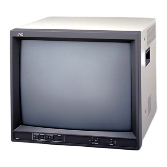
COLOUR VIDEO MONITOR
TM-A210G
TM-A210G
TM-A210G
TABLE OF CONTENTS
,
/C
,
/U
/E
BASIC CHASSIS
T1B1
No.52119
2003/6
Advertisement
Chapters
Table of Contents

Related Manuals for JVC TM-A210G/C


Summary of Contents for JVC TM-A210G/C
-
Page 1: Table Of Contents
SERVICE MANUAL COLOUR VIDEO MONITOR 52119 2003 TM-A210G TM-A210G TM-A210G BASIC CHASSIS T1B1 TABLE OF CONTENTS PRECAUTION............... . . 1-3 SPECIFIC SERVICE INSTRUCTIONS . - Page 2 Colour System PAL / NTSC 3.58 Environmental Conditions Operation Temperature : 0°C~40°C (32°F~104°F) Operation Humidity : 20%~80% (non-condensing) Power Input AC 220V-240V, 50Hz/60Hz [TM-A210G/C, TM-A210G/E] AC 120V, 60Hz [TM-A210G/U] Power Consumption 0.9A [TM-A210G/C, TM-A210G/E] 1.3A [TM-A210G/U] Picture Tube Full-square type 90° deflection in-line gun Vertical line trio type phosphor stripe pitch 0.63mm / 0.64mm (H/V)
-
Page 3: Precaution
SECTION 1 PRECAUTION SAFETY PRECAUTIONS [EXCEPT FOR UK] (1) The design of this product contains special hardware, (8) When service is required, observe the original lead dress. many circuits and components specially for safety Extra precaution should be given to assure correct lead purposes. - Page 4 SAFETY PRECAUTIONS [FOR UK] (1) The design of this product contains special hardware and many circuits and components specially for safety purposes. For continued protection, no changes should be made to the original design unless authorized in writing by the manufacturer. Replacement parts must be identical to those used in the original circuits.
- Page 5 SAFETY PRECAUTIONS [FOR US] (1) The design of this product contains special hardware, many (10) Isolation Check (Safety for Electrical Shock Hazard) circuits and components specially for safety purposes. For After re-assembling the product, always perform an isolation continued protection, no changes should be made to the original check on the exposed metal parts of the cabinet (antenna design unless authorized in writing by the manufacturer.
-
Page 6: Specific Service Instructions
SECTION 2 SPECIFIC SERVICE INSTRUCTIONS FEATURES • High-resolution full square CRT is adopted. The excelled color reproducibility and the high resolution that are required of a wide range monitor's use are realized. • It can respond to both NTSC and PAL signal system. The incoming signal was discriminated and the automatic selection function that changes the mode automatically is adopted. -
Page 7: Disassembly
SECTION 3 DISASSEMBLY DISASSEMBLY PROCEDURE 3.1.5 REMOVING THE SPEAKER • Remove the TOP COVER. 3.1.1 REMOVING THE TOP COVER (1) As shown in Fig.2, slightly spread the claws of the speaker (1) Pull out the power cord from AC inlet. holder, and pull up the SPEAKER to remove it. - Page 8 TOP COVER FRONT PANEL ASS'Y CRT SOCKET PWB FRONT CONTROL PWB MAIN PWB FBT HOLDER SIGNAL PWB AUDIO PWB REMOVE THE SPEAKER TERMINAL BRACKET SPEAKER HOLDER REAR PANEL SPEAKER FRONT Fig. 2 POWER CORD Fig.1 1-8 (No.52119)
- Page 9 MEMORY IC REPLACEMENT 3.2.1 MEMORY IC This monitor uses the memory IC. In the memory IC, there are memorized data for correctly operating for the video and deflection circuits. When replacing the memory IC, be sure to use IC written with the initial values of data. 3.2.2 MEMORY IC REPLACEMENT PROCEDURE 1.
- Page 10 3.2.3 FACTRY SETTING VALUE INITIAL SETTING VALUE TABLE [SET-UP MENU] Setting item Setting content / Range Initial setting value H. POSITION -05 ~ +05 WHITE BALANCE CUTOFF (R / G / B) -09 ~ +09 DRIVE (R / B) -09 ~ +09 CONTROL LOCK ON / OFF STATUS DISPLAY...
- Page 11 3.2.4 SERVICE MENU SETTING ITEMS SIGNAL BLOCK DEFLECTION BLOCK Item No. Setting content Item No. Setting content BRIGHT HORIZONTAL POSITION CONTRAST VERTICAL SIZE CHROMA(PAL) VERTICAL SIDE PIN CORRECTION CHROMA(NTSC) VERTICAL CENTER CHROMA(SECAM) VERTICAL LINEARITY PHASE(NTSC) In addition to the ones listed above, the following DEFLECTION BRIGHT(16:9) BLOCK are also available.
- Page 12 REPLACEMENT OF CHIP COMPONENT 3.3.1 CAUTIONS (1) Avoid heating for more than 3 seconds. (2) Do not rub the electrodes and the resist parts of the pattern. (3) When removing a chip part, melt the solder adequately. (4) Do not reuse a chip part after removing it. 3.3.2 SOLDERING IRON (1) Use a high insulation soldering iron with a thin pointed end of it.
-
Page 13: Adjustment
SECTION 4 ADJUSTMENT ADJUSTMENT PREPARATION (1) There are 2 ways of adjusting this unit: One is with the MENU as On-Screen-Display and the other is the conventional method using adjustment parts and components. (2) The adjustment using the On-Screen-Display is made on the basis of the initial setting values. The setting values which adjust the screen to the optimum condition can be different from the initial setting values. - Page 14 ADJUSTMENT LOCATIONS FRONT CHROMA VIDEO A CONTRAST VIDEO B POWER /PHASE /BRIGHT MENU -(DOWN) +(UP) VOLUME VIDEO B VIDEO A /SELECT FRONT CONTROL PWB POWER SW SIGNAL FRONT VR1401 MAIN PWB H. SIZE VR SIGNAL VR1901 S1401 B1 ADJ VR V CENTER SW AUDIO CN1001...
- Page 15 AUDIO PWB MAIN PWB AUDIO A TP-47B AUDIO B TP-E TP-47G IC8602 REMOTE (INPUT /ASPECT) CRT SOCKET PWB (SOLDER SIDE) IC8601 SPEAKER CN8003 SIGNAL PWB MD6201 VIDEO A VIDEO B IC6731 Y/C IN Y/C OUT SHIELD CASE CN6001 CN6002 FRONT CONTROL PWB (No.52119)1-15...
- Page 16 BASIC OPERATION OF SERVICE MENU 4.5.1 SERVICE MENU ITEMS With the SERVICE MENU, various settings can be made, and they are broadly classified in the following items of adjustments. It is no requirement for adjustment the portion of the DEFLECTION BLOCK and CONTROL BLOCK. SIGNAL BLOCK This block adjusts the data of the various signal circuit controls.
- Page 17 4.5.3 OPERATION OF < BLOCK SELECT > SCREEN While the SERVICE MENU < BLOCK SELECT > screen is displaying, in accordance with “FUNCTION DISPLAY” at the lower side of the screen, be able to operate the various items. < BLOCK SELECT > SIGNAL BLOCK WHITE BALANCE BLOCK DEFLECTION BLOCK...
- Page 18 4.5.5 SERVICE MENU FLOW CHART SERVICE MENU <BLOCK SELECT> SCREEN < BLOCK SELECT > SIGNAL BLOCK WHITE BALANCE BLOCK DEFLECTION BLOCK CONTROL BLOCK DEF CTRL EXIT SIGNAL BLOCK CUTOFF ADJUSTMENT DISP <S01>: EXIT R CUTOFF : RGB SERV EXIT WHITE BALANCE BLOCK MENU SCREEN DRIVE ADJUSTMENT <...
- Page 19 INITIAL SETTING VALUE OF SERVICE MENU [SIGNAL BLOCK] Setting item Variable range Initial setting value BRIGHT 000~255 CONTRAST 000~255 CHROMA (PAL) 000~255 CHROMA (NTSC) 000~255 CHROMA (SECAM) 000~255 PHASE (NTSC) 000~127 BRIGHT (16:9) -128~+127 -008 CONTRAST (16:9) -128~+127 -005 CONTRAST (9300) -128~+127 CHROMA (NTSC 9300) -128~+127...
- Page 20 [CONTROL BLOCK] (This is a fixed value. Don’t adjust it.) Setting item Variable range Initial setting value MODEL 000~011 UPPER 000~255 BRIGHT POINT LOWER 000~255 UPPER 000~255 CONTRAST POINT LOWER 000~255 UPPER 000~255 CHROMA POINT LOWER 000~255 UPPER 000~127 PHASE POINT LOWER 000~127 OSD HORIZONTAL POSITION...
- Page 21 ADJUSTMENT PROCEDURE 4.7.1 CHECK ITEM Measuring Item Test point Adjustment part Description instrument HIGH VOLTAGE HV voltmeter CRT anode SCREEN VR (1) Select WHITE BALANCE BLOCK with [in FBT] [CONTRAST/BRIGHT] button (< W/B >) from < BLOCK SELECT > SERVICE MENU screen. (2) Select CUTOFF adjustment mode with [CHROMA/ PHASE] button (<...
- Page 22 4.7.3 HIGH VOLTAGE HOLD DOWN CIRCUIT CHECK Measuring Item Test point Adjustment part Description instrument HIGH VOLTAGE HV voltmeter X-RAY • After repairing the high voltage hold down circuit, this HOLD DOWN (S1 connector circuit shall be checked to operate correctly. CIRCUIT Resistor 3-pin, 4-pin)
- Page 23 4.7.5 DEFLECTION CIRCUIT There are 4 modes of DEFLECTION adjustment depending upon the kind of input signals. The adjustments must always be carried out in regular sequence given below. If you change the figures in the course of the adjustments by returning to the preceding steps, all adjustments come to nothing. The screen aspect ratio 4:3 at 50Hz (PAL) is regarded as the reference value for all adjustments.
- Page 24 Measuring Item Test point Adjustment part Description instrument V. POSITION Signal V. CENTER SW (1) Input the circle pattern signal. generator (S1401) (2) Adjust V. CENTER SW to agree with CRT center [MAIN PWB] and signal center of vertical direction. V.
- Page 25 Measuring Item Test point Adjustment part Description instrument SIDE PIN Signal [DEFLECTION • Should not adjustment except for in case of under the CORRECTION generator BLOCK] condition that remarkably bad about vertical linearity, & D03 (SIDE PIN (1) Input the crosshatch pattern signal. V.
- Page 26 4.7.6 VIDEO CIRCUIT When you perform WHITE BALANCE adjustment, be sure to input a video composite signal. Moreover, set the aspect ratio to 4:3. It is no requirement to adjust in 16:9 mode. Measuring Item Test point Adjustment part Description instrument WHITE Signal...
- Page 27 Measuring Item Test point Adjustment part Description instrument WHITE Signal [WHITE BALANCE • Check the LOW LIGHT adjustment has been finished BALANCE generator BLOCK] correctly before performing HIGH LIGHT adjustment. (HIGH LIGHT) 6500 R DRIVE (1) Input the black-and-white signal (Included 100% 6500K &...
- Page 28 Measuring Item Test point Adjustment part Description instrument SUB BRIGHT Signal [SIGNAL BLOCK] • Under the condition that Low light adjustment has been generator S01 (BRIGHT) correctly finished. (1) Input the black and white signal (included 0% black). (2) Select the SIGNAL BLOCK with [CHROMA/PHASE] button (<...
- Page 29 Measuring Item Test point Adjustment part Description instrument PAL CHROMA Signal TP-47B [SIGNAL BLOCK] (1) Input the PAL full colour bar signal (included 75% generator TP-E S03(PAL CHROMA) white signal). [CRT SOCKET (2) Connect the oscilloscope probe to TP-47B and TP- Oscilloscope PWB] (3) Select the SIGNAL BLOCK with [CHROMA/PHASE]...
- Page 30 Measuring Item Test point Adjustment part Description instrument NTSC 3.58 Signal TP-47B [SIGNAL BLOCK] (1) Input the NTSC 3.58 full colour bar signal (included PHASE generator TP-E S06 (NTSC PHASE) 75% white signal). [CRT SOCKET (2) Connect the oscilloscope probe to TP-47B and TP- Oscilloscope PWB] (3) Select the SIGNAL BLOCK with [CHROMA/PHASE]...
- Page 31 PURITY AND CONVERGENCE PURITY ADJUSTMENT (1) Demagnetize CRT with the demagnetizer. WEDGE DEFLECTION YOKE (2) Loosen the retainer screw of the deflection yoke. (3) Remove the wedges. (4) Input a green raster signal from the signal generator, and turn the screen to green raster. P / C MAGNETS (5) Move the deflection yoke backward.
- Page 32 STATIC CONVERGENCE ADJUSTMENT (1) Input a crosshatch signal. (2) Using 4-pole convergence magnets, overlap the red and blue lines in the center of the screen (Fig.1) and turn them (FRONT VIEW) to magenta (red/blue). (3) Using 6-pole convergence magnets, overlap the magenta (red/blue) and green lines in the center of the screen and turn them to white.
-
Page 33: Trouble Shooting
SECTION 5 TROUBLE SHOOTING OUTLINE SELF DIAGNOSIS SCREEN This model includes a SELF DIAGNOSIS FUNCTION that checks the circuit operating status and in event of malfunction, PROTECTION displays and stores the data in a memory. The data are stored in : x 3 X-RAY memory. - Page 34 VICTOR COMPANY OF JAPAN, LIMITED AV & MULTIMEDIA COMPANY VIDEO DISPLAY CATEGORY 12, 3-chome, Moriya-cho, kanagawa-ku, Yokohama, kanagawa-prefecture, 221-8528, Japan (No.52119) Printed in Japan...
- Page 35 PARTS LIST CAUTION The parts identified by the symbol are important for the safety . Whenever replacing these parts, be sure to use specified ones to secure the safety. The parts not indicated in this Parts List and those which are filled with lines --- in the Parts No. columns will not be supplied. P.
- Page 36 FRONT CONTROL P.W.BOARD ASS'Y (FX-4091A-H2) ..............3-8 SIGNAL P.W.BOARD ASS'Y (FX-6140A-H2) ................... 3-8 AUDIO P.W.BOARD ASS'Y (FX-8032A-H2) ..................3-9 PACKING [TM-A210G/U , TM-A210G/E] ....................3-11 PACKING PARTS LIST [TM-A210G/U , TM-A210G/E] ................3-11 PACKING [TM-A210G/C] ........................3-12 PACKING PARTS LIST [TM-A210G/C] ....................3-12 3-2(No.52119)
-
Page 37: Exploded View Parts List -1
EXPLODED VIEW PARTS LIST -1 Ref.No. Part No. Part Name Description Local CM12970-005-MH FRONT PANEL CM48149-A01 JVC MARK CM46757-001-H SPRING CM46756-A01 POWER KNOB LC21251-001B-H CONTROL SHEET EXPLODED VIEW -1 (No.52119)3-3... -
Page 38: Exploded View Parts List -2
4mm x 12mm(x3) LC11569-001A-H FBT HOLDER LC30475-008A-H WARNING LABEL TM-A210G/E,TM-A210G/U LC11570-001A-C REAR PANEL LC21304-001A-0L ROLL R LABEL TM-A210G/C LC21283-001A-0L ROLL R LABEL TM-A210G/E,TM-A210G/U QYSBSF4012Z TAP SCREW 4mm x 12mm CM44287-00C ASSY SCREW (x7) CM12975-008-H TOP COVER... -
Page 39: Exploded View -2
EXPLODED VIEW -2 DY01 CRT SOCKET FRONT CONTROL PWB SIGNAL PWB T1501 MAIN PWB AUDIO PWB POWER CORD (No.52119)3-5... -
Page 40: Printed Wiring Board Parts List
PRINTED WIRING BOARD PARTS LIST Ref No. MAIN P.W.BOARD ASS'Y (FX-1184A-H2) Part No. Part Name Description Local Ref No. Part No. Part Name Description Local C1464 QEHR1HM-226Z E CAPACITOR 22uF 50V M C1465 QCS31HJ-101Z C CAPACITOR 100pF 50V J IC1421 LA78041 C1466 QEHR1HM-226Z E CAPACITOR... -
Page 41: Crt Socket P.w.board Ass'y (Fx-3073A-H2)
Ref No. Ref No. Part No. Part Name Description Local Part No. Part Name Description Local R1463 QRE141J-681Y C RESISTOR 680Ω 1/4W J CN1001 QGB1505J1-15 CONNECTOR B-B (1-15) R1464 QRE141J-331Y C RESISTOR 330Ω 1/4W J CN1002 QGB1505J1-15 CONNECTOR B-B (1-15) R1466 QRE141J-102Y C RESISTOR... -
Page 42: Front Control P.w.board Ass'y (Fx-4091A-H2)
Ref No. Ref No. Part No. Part Name Description Local Part No. Part Name Description Local R3330 NRSA63J-221X MG RESISTOR 220Ω 1/16W J Q6203 2SC2412K/QR/-X TRANSISTOR R3331 NRSA63J-680X MG RESISTOR 68Ω 1/16W J Q6220 2SC2412K/QR/-X TRANSISTOR R3333 NRSA63J-221X MG RESISTOR 220Ω... -
Page 43: Audio P.w.board Ass'y (Fx-8032A-H2)
Ref No. Ref No. Part No. Part Name Description Local Part No. Part Name Description Local C6404 QEHR1HM-335Z E CAPACITOR 3.3uF 50V M R6507 NRSA63J-0R0X MG RESISTOR 0Ω 1/16W J C6405 NCB31HK-102X C CAPACITOR 1000pF 50V K R6710 NRSA63J-222X MG RESISTOR 2.2kΩ... - Page 44 Ref No. Part No. Part Name Description Local D8733 MA3091/M/-X Z DIODE C8001 NCB31HK-391X C CAPACITOR 390pF 50V K C8002 NCB31HK-391X C CAPACITOR 390pF 50V K C8144 NCF31CZ-104X C CAPACITOR 0.1uF 16V Z C8145 NCF31CZ-104X C CAPACITOR 0.1uF 16V Z C8146 QEHR1CM-107Z E CAPACITOR 100uF 16V M...
-
Page 45: Packing [Tm-A210G/U , Tm-A210G/E]
PACKING [TM-A210G , TM-A210G PACKING PARTS LIST [TM-A210G , TM-A210G Ref.No. Part No. Part Name Description Local LC11194-005A-H PACKING CASE LC20989-001A-H CORNER LABEL (x2) CP11655-00C-H CUSHION ASSY 4 pcs in 1set QMP1110-244K POWER CORD 2m BLACK TM-A210G/U QPA01203005 POLY BAG 12cm x 30cm TM-A210G/U... -
Page 46: Packing [Tm-A210G/C]
PACKING [TM-A210G PACKING PARTS LIST [TM-A210G Ref.No. Part No. Part Name Description Local LC11570-001A-C PACKING CASE LC20989-001A-H CORNER LABEL (x2) CP11655-00C-H CUSHION ASSY 4 pcs in 1set QMPS210-200-JC POWER CORD 2m BLACK CP30967-003-H POLY BAG CP30966-001-H POLY BAG ... - Page 47 TM-A210G , TM-A210G , TM-A210G CONTENTS SEMICONDUCTOR SHAPES ..............2-2 STANDARD CIRCUIT DIAGRAM BLOCK DIAGRAM ..................2-3 NOTE ON USING CIRCUIT DIAGRAMS CIRCUIT DIAGRAMS ..................2-5 1.SAFETY Type SIGNAL PWB CIRCUIT DIAGRAM ......................2-5 The components identified by the symbol and shading are No indication :Ceramic capacitor MAIN PWB CIRCUIT DIAGRAM ........................
-
Page 48: Block Diagram
BLOCK DIAGRAM AUDIO A AUDIO PWB IC8602 IC8601 AUDIO OUT AUDIO B AUDIO INPUT INPUT REMOTE ASPECT ASPECT ASPECT INPUT VIDEO A IC6732 SIGNAL PWB VIDEO A MEMORY IC6731 MICRO COMPUTER Q3301- Q3306 IC6202 IC6201 IC6205 VIDEO B MD6201 VIDEO COMB FILTER PROCESSOR CRT SOCKET... -
Page 49: Circuit Diagrams
CIRCUIT DIAGRAMS IC6202 IC6731 IC6201 4 IC6201 IC6201 IC6201 IC6201 IC6201 IC6205 IC6201 IC6201 IC6201 IC6201 SIGNAL PWB CIRCUIT DIAGRAM PIN NO. VOLTAGE (V) PIN NO. VOLTAGE (V) C6103 C6102 IC6201 MD6201 CE42599-002 IC6205 LA7016 IC6731 IC6731 MD6201 MD6201 IC6731 R6104 4.7k GND2... -
Page 50: Main Pwb Circuit Diagram
MAIN PWB CIRCUIT DIAGRAM CRT SOCKET T1501 PIN NO. VOLTAGE (V) IC1421 1 7 IC1421 5 IC1421 6 Q1511 B T1501 T1501 T1501 Q1501 G Q1501 D Q1511 IC1421 1200 CN100U CN1001 CN10S2 CN1002 CN1003 QGB1505J1-15 QGA2501F1-03 QGB1505J1-15 QGB1505J1-15 26.7 GND2 GND2 GND2... -
Page 51: Crt Socket Pwb Circuit Diagram
CRT SOCKET CIRCUIT DIAGRAM R3313 L3306 QQL244J-151Z R3312 R3304 Q3303 2SC4544-LB VIDEO_OUT L3305 R3311 R3342 C3316 R3341 OPEN 220p QRZ0111-102 C3318 OPEN TP-47G TP-47B GND2 GND2 Q3306 2SC3311A/QR/-T Q3307 R3320 C3312 R3337 VIDEO_OUT OPEN R3347 R3332 R3329 GND2 OPEN C3313 180p R3310 CN300T... -
Page 52: Front Pwb Circuit Diagram
FRONT PWB CIRCUIT DIAGRAM CN40SW QGA7901F1-04 S4901 QSP4K21-C01 R4803 R4806 1.5k Q4803 D4803 R4802 R4801 GL2EG6 Q4801 S4808 QSW0619-003Z R4810 4.7k D4801 R4813 R4807 GL2EG6 4.7k 4.7k R4804 Q4802 S4809 QSW0619-003Z CN400A QGA2501F1-08 D4802 GL2EG6 FRONT CONTROL PB ASSY FX-4091A-H2 R4805 GND2 S4805... -
Page 53: Audio Pwb Circuit Diagram
AUDIO PWB CIRCUIT DIAGRAM IC8602 LA7016 IC8601 AN5265 C8163 C8164 GND2 GND2 Q8161 R8162 J8005 C8161 100k CEMN036-005 R8161 R8605 QRZ9021-220 R8182 100k GND2 C8166 R8614 C8603 C8001 OPEN Q8181 100k D8161 C8167 390p R8163 OPEN C8162 QTNC1HM-225Z C8610 MA3120/M/-X 100k AUDIO 2200... -
Page 54: Pattern Diagrams
PATTERN DIAGRAMS MAIN PWB PATTERN FRONT CL1003 CL1001 W1205 W1425 C1462 W1209 R1961 C1994 R1467 R1468 W1221 C1926 R1461 H1001 H1005 K1921 IC1461 W1432 R1925 IC1961 W1227 D1989 C1922 R1927 R1463 W1431 W1601 D1921 K1952 W1633 R1464 C1465 W1434 D1987 W1413 C1466 R1478... -
Page 55: Signal Pwb Pattern
SIGNAL PWB PATTERN MD6201 C6228 R6213 C6210 Q6350 Q6101 W6038 W6076 W6093 C6224 C6102 C6202 FRONT C6350 W6091 L6351 R6202 C6105 Q6201 R6103 C6351 W6097 W6090 W6094 W6036 W6037 C6225 R6218 R6214 W6099 L6701 W6011 R6222 W6035 R6101 R6223 Q6220 W6034 D6121 Q6121... -
Page 56: Crt Socket Pwb Pattern
CRT SOCKET PWB PATTERN AUDIO PWB PATTERN C3314 R3302 C3320 C3316 R3342 W3009 R3304 R3320 R3341 L3305 W3012 J8005 R3323 R8162 CL3004 R3322 C8161 R3334 W8019 R3337 Q8161 R3331 C3313 R3346 R8753 R3330 R3329 R3318 D8161 R8603 C3309 C8604 R3321 R3333 C8609 TP-E...