Table of Contents
Advertisement
Quick Links
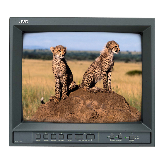
COLOR VIDEO MONITOR
TM-A130SU
For Customer Use:
Enter below the Serial No. which is located on the rear of
the cabinet. Retain this information for future reference.
TM-A130SU
Model No. :
Serial No. :
INSTRUCTIONS
–
+
PHASE
CHROMA
BRIGHT
CONTRAST
MENU
VOLUME/SELECT
TM-A130SU
B
A
ON
OFF
INPUT SELECT
POWER
Advertisement
Table of Contents

Related Manuals for JVC JVC TM-A130SU


Summary of Contents for JVC JVC TM-A130SU
- Page 1 COLOR VIDEO MONITOR TM-A130SU For Customer Use: Enter below the Serial No. which is located on the rear of the cabinet. Retain this information for future reference. TM-A130SU Model No. : Serial No. : INSTRUCTIONS – INPUT SELECT PHASE CHROMA BRIGHT CONTRAST MENU...
-
Page 2: Safety Precautions
Thank you for purchasing this JVC color video monitor. Before using it, read and follow all instructions carefully to take full advantage of the monitor's capabilities. SAFETY PRECAUTIONS WARNING : TO PREVENT FIRE OR SHOCK HAZARDS, DO NOT EXPOSE THIS MONITOR TO RAIN OR MOISTURE. -
Page 3: Table Of Contents
CONTENTS SAFETY PRECAUTIONS ... 2 CONTROLS AND FEATURES ... 4 HOW TO HANDLE BASIC OPERATIONS ... 6 HOW TO USE THE MENU FUNCTIONS ... 7 HOW TO INITIALIZE THE SETTING ... 10 BASIC CONNECTION EXAMPLE ... 11 TROUBLESHOOTING ... 12 SPECIFICATIONS ... -
Page 4: Controls And Features
CONTROLS AND FEATURES FRONT VIEW <Front Panel> – INPUT SELECT PHASE CHROMA BRIGHT CONTRAST MENU VOLUME/SELECT POWER TM-A130SU 1 Phase button [PHASE Press this button to set the picture hue adjustment mode. Adjust the value with the VOLUME/SELECT Also used as a control button in the menu function mode. 2 Chroma button [CHROMA Press this button to set the picture color density adjust- ment mode. -
Page 5: Rear View
REAR VIEW <Rear Panel> VIDEO Y/C IN 14 Video A terminals [VIDEO A IN/OUT] Video signal input (IN) and output (OUT) terminals. The output terminal is bridge-connected. : Video signal input terminal OUT : Bridge-connected video signal output terminal Notes: * For corresponding audio signals, use the AUDIO A terminals * Also refer to the BASIC CONNECTION EXAMPLE on... -
Page 6: How To Handle Basic Operations
HOW TO HANDLE BASIC OPERATIONS BASIC OPERATION 1. Press the POWER switch to turn on the power. ON : Power turns ON. (Power indicator: lit) OFF : Power turns OFF. (Power indicator: unlit) POWER 2. Press the INPUT SELECT button to choose input. Selects video/audio signals input to terminals on the rear panel. -
Page 7: How To Use The Menu Functions
HOW TO USE THE MENU FUNCTIONS DISPLAY AND SELECTION IN THE <MENU> SCREEN MODE (SETTING) You can set the following menu items. Set them depending on your needs. • SHARPNESS • COLOR SYSTEM 1. Press the MENU button. The <MENU> screen is displayed. MENU 2. - Page 8 HOW TO USE THE MENU FUNCTIONS DISPLAY AND SELECTIONS IN THE <SET-UP MENU> MODE (SETTING) You can set the following set-up menu items. ● H. POSITION ● WHITE BALANCE Note: ● Parameters for H. POSITION can be set separately depending on the video input (Input A or Input B) selected by the input select buttons on the front panel.
- Page 9 Set-up menu items H. POSITION Adjusts the horizontal position of the screen (+ : Horizontal position shifts to the right/–: Horizontal position shifts to the left) WHITE BALANCE Adjusts the white balance DRIVE R.DRIVE Adjusts red level B.DRIVE Adjusts blue level CUT OFF R.
-
Page 10: How To Initialize The Setting
HOW TO INITIALIZE THE SETTING SCREEN DISPLAY AND SELECTIONS IN THE <SET-UP MENU> RESET MODE You can set <MENU> and <SET-UP MENU> screen items, picture adjustment items and the volume level to their factory-set (initial) values. 1. Press the POWER ( OFF ( POWER 2. -
Page 11: Basic Connection Example
BASIC CONNECTION EXAMPLE Notes: ● Before connecting your system, make sure that all units are turned off. ● The illustration below shows some examples of different connections. Terminal connections may differ depending on the component connected. Be sure to refer to the instructions provided with the unit(s) you are connecting. ●... -
Page 12: Troubleshooting
TROUBLESHOOTING Solutions to common problems related to your monitor are described here. If none of the solutions presented here solves the problem, unplug the monitor and consult a JVC-authorized dealer or service center for assistance. Problems No power supply. Is the power plug loosened or disconnected? -
Page 13: Specifications
SPECIFICATIONS MODEL Type Color system Picture tube Effective screen size Scanning frequency Horizontal resolution Input terminals VIDEO A VIDEO B AUDIO A AUDIO B Audio power output Built-in speaker Environmental conditions Power requirements Power consumption Dimensions Weight Accessory * Illustrations used in this manual are for explanatory purposes only. The appearance of the actual product may differ slightly. * Dimensions and weight are approximate. - Page 14 7 Dimensions < Front View > 13-5/8 (346) 11-3/8 (287) – PHASE CHROMA BRIGHT CONTRAST MENU VOLUME/SELECT TM-A130SU 11-1/4 (284) * Asterisks ( ) are used to indicate front panel dimensions. 7 Y/C (Mini DIN 4 pin) terminal specification Y/C IN <...
- Page 16 JVC PROFESSIONAL PRODUCTS COMPANY DIVISION OF US JVC CORP. 1700 Vallery Road Wayne, NJ07470 JVC CANADA INC. 21 Finchdene Square, Scarborough Ontario M1X 1A7 LCT0367-002A-H 0699-Tu-U-JMT © 1999 VICTOR COMPANY OF JAPAN, LIMITED...