Emerson Bettis G01 Series Installation, Operation And Maintenance Manual
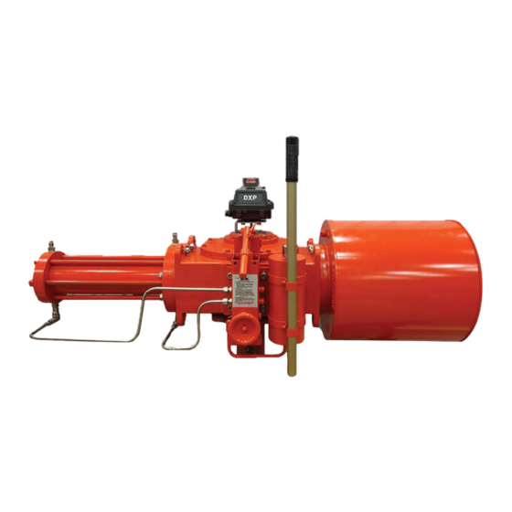
Double-acting pneumatic actuators with m18 hydraulic override
Hide thumbs
Also See for Bettis G01 Series:
- Disassembly and reassembly (58 pages) ,
- Installation, operation and maintenance manual (18 pages)

Related Manuals for Emerson Bettis G01 Series


Summary of Contents for Emerson Bettis G01 Series
- Page 1 Installation, Operation and Maintenance Manual VA-DC-000-1803 Rev. 2 July 2020 Bettis G01 through G10 Double-Acting Pneumatic Actuators with M18 Hydraulic Override...
- Page 2 Notes Installation, Operation and Maintenance Manual July 2020 VA-DC-000-1803 Rev. 2 This page intentionally left blank.
-
Page 3: Table Of Contents
Installation, Operation and Maintenance Manual Table of Contents VA-DC-000-1803 Rev. 2 July 2020 Table of Contents Section 1: Introduction General Service Information ................1 Definitions ....................2 General Safety Information ................2 Bettis Reference Materials ................3 Service Support Items ................... 3 Lubrication and Fluid Requirements .............. - Page 4 Table of Contents Installation, Operation and Maintenance Manual July 2020 VA-DC-000-1803 Rev. 2 Section 6: Actuator Support Information Module Weights by Item Number and Actuator Housing Size ...... 39 G01 Tool Style and Wrench Size ..............41 G2 Tool Style and Wrench Size..............41 G3 Tool Style and Wrench Size..............
-
Page 5: Section 1: Introduction
Installation, Operation and Maintenance Manual Section 1: Introduction VA-DC-000-1803 Rev. 2 July 2020 Section 1: Introduction General Service Information 1.1.1 This service procedure is offered as a guide to enable general maintenance to be performed on Bettis™ G01XXX-M18, G2XXX-M18, G3XXX-M18, G4XXX-M18, G5XXX-M18, G7XXX-M18, G8XXX-M18, and G10XXX M18 Double-Acting G-Series Actuators with one Pneumatic Power Module and one M18 Hydraulic Override Module. -
Page 6: Definitions
Section 1: Introduction Installation, Operation and Maintenance Manual July 2020 VA-DC-000-1803 Rev. 2 Definitions WARNING If not observed, user incurs a high risk of severe damage to actuator and/or fatal injury to personnel. CAUTION If not observed, user may incur damage to actuator and/or injury to personnel. NOTE: Advisory and information comments provided to assist maintenance personnel to carry out maintenance procedures. -
Page 7: Bettis Reference Materials
M18 Manual Hydraulic Override System operating instructions part number VA-DC-000-1879 with M18 Assembly Drawing part number VA-ED-005-1120. NOTE: If you require a specific assembly drawing (IE: GXX-M3 OR HYD) please contact Emerson Valve Automation Bettis by phone or email at Info.Bettis@EmersonProcess.com. Service Support Items 1.5.1 Bettis module service kits. -
Page 8: Lubrication And Fluid Requirements
Section 1: Introduction Installation, Operation and Maintenance Manual July 2020 VA-DC-000-1803 Rev. 2 Lubrication and Fluid Requirements NOTE: Lubricants and hydraulic fluids other than those listed in step 1.6.1 and 1.6.2 should not be used without prior written approval of Bettis Product Engineering. 1.6.1 Lubricants: Standard and high temperature services (-20 °F to +350 °F) / (-29 °C to 176 °C) use... -
Page 9: Actuator Installation
Installation, Operation and Maintenance Manual Section 1: Introduction VA-DC-000-1803 Rev. 2 July 2020 Actuator Installation 1.9.1 Since there are many valve and actuator combinations, it is not practical to include detailed instructions for each type. Mountings are designed to be as simple as possible to keep the guess work out of the installation. -
Page 10: Actuator Operation
Section 1: Introduction Installation, Operation and Maintenance Manual July 2020 VA-DC-000-1803 Rev. 2 1.10.3 When actuator is first placed into service, it should be cycled with regulated pneumatic pressure. This is necessary because the seals have been stationary, causing them to take a "set". Therefore, the actuator should be operated through several cycles to exercise the seals so as to achieve a service ready condition. -
Page 11: Section 2: Actuator Disassembly
Installation, Operation and Maintenance Manual Section 2: Actuator Disassembly VA-DC-000-1803 Rev. 2 July 2020 Section 2: Actuator Disassembly General Disassembly WARNING Dangerous gas and/or liquids. It is possible, that the actuator may contain a dangerous gas and/or liquid. Ensure that all proper measures have been taken to prevent exposure or release of these types of contaminants before commencing any work. - Page 12 Section 2: Actuator Disassembly Installation, Operation and Maintenance Manual July 2020 VA-DC-000-1803 Rev. 2 2.2.1 Mark and record location of the ports on outer end cap (3 - 80) and inner end cap (3 - 10). 2.2.2 Refer to assembly drawing sheet 1 Detail "E". Remove two socket cap screws (3 - 130), with lock washer (3 - 140), from outer end cap (3 - 80).
- Page 13 Installation, Operation and Maintenance Manual Section 2: Actuator Disassembly VA-DC-000-1803 Rev. 2 July 2020 NOTE: Piston (3 - 30) acts as the retainer for inboard split ring halves (3 - 50). When removing the piston be careful to not lose inboard split ring halves (3 - 50). 2.2.7.2 Remove piston (3 - 30) and two split ring halves (3 - 50) from piston rod (3 - 40).
-
Page 14: Drive Module Disassembly
Section 2: Actuator Disassembly Installation, Operation and Maintenance Manual July 2020 VA-DC-000-1803 Rev. 2 Drive Module Disassembly NOTE: Review Section 2 steps 2.1.1 through 2.1.3 General Disassembly before proceeding with drive module disassembly. Refer to dwg. VA115680 for details. 2.3.1 If not already removed remove piston rod (3 - 40) from drive module. - Page 15 Installation, Operation and Maintenance Manual Section 2: Actuator Disassembly VA-DC-000-1803 Rev. 2 July 2020 2.3.11 Remove hex cap screws (1 - 120), with lock washers (1 - 115), from housing cover (1 - 20). 2.3.12 Using hex cap screws (1 - 110), install into holes vacated by hex cap screws (1 - 120).
-
Page 16: M18 Hydraulic Override Cylinder Disassembly
Section 2: Actuator Disassembly Installation, Operation and Maintenance Manual July 2020 VA-DC-000-1803 Rev. 2 2.3.23 Refer to assembly drawing sheet 2 Detail "B". Use Bettis tool part numbers 117368 (G8 / G10), 117369 (G5 / G7), 117370 (G3 / G4), or 123616 (G2) and remove retention retainer nut assemblies (1 - 60) and (9 - 60) from guide block (1 - 30). -
Page 17: M18 Pump Disassembly
Installation, Operation and Maintenance Manual Section 2: Actuator Disassembly VA-DC-000-1803 Rev. 2 July 2020 2.4.2 Remove all the piping from the M18 override cylinder outer end cap (7 - 80) and inner end cap (7 - 10). 2.4.3 Mark and record location of the ports on outer end cap (7 - 80) and inner end cap (7 - 10). - Page 18 Section 2: Actuator Disassembly Installation, Operation and Maintenance Manual July 2020 VA-DC-000-1803 Rev. 2 2.5.1 Place the M18 pump control knob (25 - 200) in the auto position. Use dwg. VA-ED-005-1120 for this Section. NOTE: Control knob (25 - 200) is located in front and at the bottom of the M18 pump manifold (20 - 10 - 10).
-
Page 19: M18 Reservoir Disassembly
Installation, Operation and Maintenance Manual Section 2: Actuator Disassembly VA-DC-000-1803 Rev. 2 July 2020 2.5.10 Remove flat head screw (20 - 10 - 330) from the manifold (20 - 10 - 10). 2.5.11 Remove disc, control valve (20 - 10 - 290) from the manifold (20 - 10 - 10). 2.5.12 Remove seal O-ring (20 - 20 - 40) from the manifold (20 - 10 - 10). -
Page 20: Section 3: Actuator Reassembly
Section 3: Actuator Reassembly Installation, Operation and Maintenance Manual July 2020 VA-DC-000-1803 Rev. 2 Section 3: Actuator Reassembly General Reassembly CAUTION Check shelf life of seals. Only new seals, which are still within the seal’s expectant shelf life, should be installed into the actuator being refurbished. 3.1.1 Remove and discard all old seals and gaskets. - Page 21 Installation, Operation and Maintenance Manual Section 3: Actuator Reassembly VA-DC-000-1803 Rev. 2 July 2020 3.2.1 If guide bar bearings are being replaced install new bearings into guide block (1 - 30). NOTE: The guide bar bearing must be pressed into guide block guide bar bore with the seam located ±5 degrees of the top or bottom centerline as shown in Section A-A.
- Page 22 Section 3: Actuator Reassembly Installation, Operation and Maintenance Manual July 2020 VA-DC-000-1803 Rev. 2 NOTE: The spherical side of the washer will go on the extension rod assembly facing the head of the extension rod assembly. 3.2.11 Install extension rod assembly (9 - 50) into guide block (1 - 30) and up against the first spherical washer (9 - 40).
- Page 23 Installation, Operation and Maintenance Manual Section 3: Actuator Reassembly VA-DC-000-1803 Rev. 2 July 2020 3.2.20 Align hole in guide block (1 - 30) with the matching holes in the two yoke/guide block bushings (2 - 30) and the slots in the arms of yoke (1 - 70). NOTE: The yoke pin can be held in place by installing a screw into the .375 - 16 UNC tapped hole in the upper end of yoke pin (1 - 80).
- Page 24 Section 3: Actuator Reassembly Installation, Operation and Maintenance Manual July 2020 VA-DC-000-1803 Rev. 2 3.2.30 NOTE: Do this step only if groove pins (1 - 130) have been pulled or if the pins are being replaced. Drive groove pins (1 - 130) through housing cover (1 - 20) and into housing (1 - 10).
-
Page 25: Pneumatic Power Module Reassembly
Installation, Operation and Maintenance Manual Section 3: Actuator Reassembly VA-DC-000-1803 Rev. 2 July 2020 3.2.39 Place lock washers (1 - 170) onto hex cap screws (1 - 160). 3.2.40 Install and tighten hex cap screws (1 - 160) with lock washers through yoke cover (1 - 150) and into housing cover (1 - 20). - Page 26 Section 3: Actuator Reassembly Installation, Operation and Maintenance Manual July 2020 VA-DC-000-1803 Rev. 2 3.3.2 Torque tighten piston rod (3 - 40) to the lubricated torque as listed in the following Table. Table 3. Piston Rod Torque Information Torque (±5%) Torque (±5%) Housing Housing...
- Page 27 Installation, Operation and Maintenance Manual Section 3: Actuator Reassembly VA-DC-000-1803 Rev. 2 July 2020 3.3.11.1 Install two sets of rod T-seals (4 - 50) into the internal diameter seal grooves of piston (3 - 30). 3.3.11.2 Install a back-up ring on each side of the T-seal. 3.3.11.3 When installing the back-up rings, do not align the skive-cuts.
-
Page 28: G2 And G3 Early Model Pneumatic Power Module Reassembly
Section 3: Actuator Reassembly Installation, Operation and Maintenance Manual July 2020 VA-DC-000-1803 Rev. 2 3.3.23 Install tie bar nuts (3 - 90) onto tie bars (3 - 20). Torque tighten tie bar nuts, alternately in 100 lb-ft / Nm increments, until a final lubricated torque, as listed in the following Table, has been achieved. - Page 29 Installation, Operation and Maintenance Manual Section 3: Actuator Reassembly VA-DC-000-1803 Rev. 2 July 2020 3.4.4 Install piston rod (3 - 40) through inner end cap (3 - 10). NOTE: The piston rod end with retainer grooves to be on the outboard side of inner end cap (3 - 10). NOTE: Piston will be torque tighten when installed into the drive module refer to Section 5, step 5.2.5.
- Page 30 Section 3: Actuator Reassembly Installation, Operation and Maintenance Manual July 2020 VA-DC-000-1803 Rev. 2 3.4.10 Install two split ring halves (3 - 50) into the piston rod, in back of the piston and retain with retainer ring (3 - 60). 3.4.11 Coat two tie bars (3 - 20) with lubricant and install by carefully pushing tie bars through piston (3 - 30) and rod T-seal (4 - 50).
-
Page 31: M18 Hydraulic Override Cylinder Reassembly
Installation, Operation and Maintenance Manual Section 3: Actuator Reassembly VA-DC-000-1803 Rev. 2 July 2020 3.4.20 Install lock washers (3 - 140) onto socket cap screws (3 - 130). 3.4.21 Install and tighten socket cap screws (3 - 130), with lock washers (3 - 140), into outer end cap (3 - 80). - Page 32 Section 3: Actuator Reassembly Installation, Operation and Maintenance Manual July 2020 VA-DC-000-1803 Rev. 2 NOTE: To move the piston (7 - 30) through the bore of cylinder (7 - 70) may require mechanical assistance. 3.5.11 Coat one piston seal (8 - 60) with fluid and install into the piston external seal groove.
-
Page 33: M18 Pump Reassembly
Installation, Operation and Maintenance Manual Section 3: Actuator Reassembly VA-DC-000-1803 Rev. 2 July 2020 3.5.21 Install lock washers (7 - 95) onto tie bars (7 - 20) and up against outer end cap (7 - 80). 3.5.22 Install hex nuts (7 - 90) onto tie bars (7 - 20) and up against lock washers (7 - 95). 3.5.23 Torque tighten hex nuts (7 - 90) until a final lubricated torque, as listed in the following Table, has been achieved. - Page 34 Section 3: Actuator Reassembly Installation, Operation and Maintenance Manual July 2020 VA-DC-000-1803 Rev. 2 3.6.6 Install pump cyl (20 - 10 - 20) and the pin, cyl (20 - 10 - 60) into the manifold (20 - 10 - 10), note the orientation of the pump cylinder. 3.6.7 Install retnr ring (20 - 10 - 80) into the manifold to secure the pin, cyl (20 - 10 - 60).
-
Page 35: M18 Reservoir Reassembly
Installation, Operation and Maintenance Manual Section 3: Actuator Reassembly VA-DC-000-1803 Rev. 2 July 2020 3.6.20 Install cover (20 - 10 - 140) onto the manifold (20 - 10 - 10) with soc cap screws (25 - 240). 3.6.21 Install instruction tag (25 - 220) onto the cover (20 - 10 - 140). 3.6.22 Engage quick rel. -
Page 36: Actuator Testing
PED by pressuring both sides of the piston to avoid damage and over torquing of the actuator components. If future testing in the field is necessary, Emerson should be contacted for guidance. Actuator Reassembly... -
Page 37: Section 4: Field Conversions
Installation, Operation and Maintenance Manual Section 4: Field Conversions VA-DC-000-1803 Rev. 2 July 2020 Section 4: Field Conversions Construction Reversal (Exchange Module Locations) 4.1.1 Remove pneumatic power module per Section 5.1. 4.1.2 Remove M18 Hydraulic Override Cylinder per Section 5.3. 4.1.3 Using Section 5.1, reinstall the pneumatic power module onto the opposite end of housing (1 - 10) as it was previously located. -
Page 38: Section 5: Module Removal And Installation
Section 5: Module Removal and Installation Installation, Operation and Maintenance Manual July 2020 VA-DC-000-1803 Rev. 2 Section 5: Module Removal and Installation Pneumatic Power Module Removal CAUTION Refer to VA115680 for drawing details. CAUTION Use heavy duty support equipment. Due to the weight and size of power module, heavy duty support equipment will be required when removing power module from the actuator housing. -
Page 39: M18 Hydraulic Overrides Cylinder Removal
Installation, Operation and Maintenance Manual Section 5: Module Removal and Installation VA-DC-000-1803 Rev. 2 July 2020 5.2.2 Using lifting equipment move the power module up to housing (1 - 10) and install as follows: Use step 5.2.3 for G01 and step 5.2.4 for G2 through G10 actuator models. -
Page 40: M18 Hydraulic Override Cylinder Installation
Section 5: Module Removal and Installation Installation, Operation and Maintenance Manual July 2020 VA-DC-000-1803 Rev. 2 WARNING Use proper lifting equipment. Use suitable lifting equipment to support the cylinder assembly. 5.3.3 Remove hex cap screws (7 - 115), with lock washers (7 - 110), from inner end cap (7 - 10). -
Page 41: Power Swivel Module Removal
Installation, Operation and Maintenance Manual Section 5: Module Removal and Installation VA-DC-000-1803 Rev. 2 July 2020 5.4.5 Torque tighten piston rod (7 - 40) per Table 3. 5.4.6 Install lock washers (7 - 110) onto hex cap screws (7 - 115). 5.4.7 Install and tighten hex cap screws (7 - 115), with lock washers, through housing (1 - 10) and into inner end cap (7 - 10). -
Page 42: Power Swivel Module Installation
Section 5: Module Removal and Installation Installation, Operation and Maintenance Manual July 2020 VA-DC-000-1803 Rev. 2 Power Swivel Module Installation NOTE: Refer to assembly drawing sheet 2 Detail "B". X- can be 1- or 9- items as required. WARNING Check overtravel position. The actuator must be in the appropriate overtravel position. Confirm overtravel position by observing the guide block (1 - 30) is against the inner wall of housing (1 - 10). -
Page 43: Section 6: Actuator Support Information
Installation, Operation and Maintenance Manual Section 6: Actuator Support Information VA-DC-000-1803 Rev. 2 July 2020 Section 6: Actuator Support Information Module Weights by Item Number and Actuator Housing Size Table 6. Module Weight by Item Number and Actuator Housing Size Item Module Description... - Page 44 Section 6: Actuator Support Information Installation, Operation and Maintenance Manual July 2020 VA-DC-000-1803 Rev. 2 Item Module Description 2.5” Dia. H Power Module 14.1 3.0” Dia. H Power Module 21.7 4.0” Dia. H Power Module 5.0” Dia. H Power Module 6.0”...
-
Page 45: G01 Tool Style And Wrench Size
Installation, Operation and Maintenance Manual Section 6: Actuator Support Information VA-DC-000-1803 Rev. 2 July 2020 G01 Tool Style and Wrench Size Table 7. G01 Tool Style and Wrench Size Location or Recommended Item No. Wrench Size Item Qty. Description Tool Style 1 - 110 9/16”... -
Page 46: G3 Tool Style And Wrench Size
Section 6: Actuator Support Information Installation, Operation and Maintenance Manual July 2020 VA-DC-000-1803 Rev. 2 G3 Tool Style and Wrench Size Table 9. G3 Tool Style and Wrench Size Location or Recommended Item No. Wrench Size Item Qty. Description Tool Style 1 - 110 9/16”... -
Page 47: G5 Tool Style And Wrench Size
Installation, Operation and Maintenance Manual Section 6: Actuator Support Information VA-DC-000-1803 Rev. 2 July 2020 G5 Tool Style and Wrench Size Table 11. G5 Tool Style and Wrench Size Location or Recommended Item No. Wrench Size Item Qty. Description Tool Style 1 - 110 3/4”... -
Page 48: G8 Tool Style And Wrench Size
Section 6: Actuator Support Information Installation, Operation and Maintenance Manual July 2020 VA-DC-000-1803 Rev. 2 G8 Tool Style and Wrench Size Table 13. G8 Tool Style and Wrench Size Location or Recommended Item No. Wrench Size Item Qty. Description Tool Style 1 - 110 3/4”... -
Page 49: M18 Tool Style And Wrench Size
Installation, Operation and Maintenance Manual Section 6: Actuator Support Information VA-DC-000-1803 Rev. 2 July 2020 6.10 M18 Tool Style and Wrench Size Table 15. M18 Tool Style and Wrench Size Item No. Wrench Size Item Qty. 10 - 50 NUT, ACORN 3/8 - 16 UNC*HI CROWN* 5/8 Socket, Air Ratchet 20 - 10 - 210 PIPE PLUG, 3/8*5000#/SOLID* X... -
Page 50: Section 7: Troubleshooting
In the unlikely event of a fault developing, the following Fault Location Table is provided to assist the service engineer to perform troubleshooting. This Table is designed to cover as wide a range of Emerson Bettis actuators as possible. Reference to equipment not supplied should be ignored. -
Page 51: Operational Test
Installation, Operation and Maintenance Manual Section 7: Troubleshooting VA-DC-000-1803 Rev. 2 July 2020 Operational Test 7.2.1 Full Stroke Test The “Full Stroke Test” (“On-line”) must be performed to satisfy the PFD (average probability of failure on demand) value. The full stroke test frequencies will be defined by the final installer to achieve the defined SIL level. -
Page 52: Section 8: Removal And Decommissioning
If a conflict arises between this procedure and the customer's procedures, the differences should be resolved in writing between an authorized customer’s representative and an authorized Emerson/Bettis representative. CAUTION Isolate and power off actuator. Make sure actuator is isolated before removing from valve. -
Page 53: List Of Tables
Installation, Operation and Maintenance Manual List of Tables VA-DC-000-1803 Rev. 2 July 2020 List of Tables Table 1 G-Series Models .................... 3 Table 2 Housing Cover Screw Quantity and Torque ..........20 Table 3 Piston Rod Torque Information ..............22 Table 4 Tie Bar Nuts .................... -
Page 54: Appendix A: List Of Drawings
Appendix Installation, Operation and Maintenance Manual July 2020 VA-DC-000-1803 Rev. 2 Appendix A: List of Drawings Part No. 115680, GXXXX-H Pneumatic Assembly Drawing, Sheet 1 of 2 CAUTION Latest drawings can be required from Emerson. Figure A-1 Appendix... -
Page 55: Part No. 115680, Gxxxx-H Pneumatic Assembly Drawing, Sheet 2 Of 2
Installation, Operation and Maintenance Manual Appendix VA-DC-000-1803 Rev. 2 July 2020 Part No. 115680, GXXXX-H Pneumatic Assembly Drawing, Sheet 2 of 2 Figure A-2 Appendix... -
Page 56: Part No. Va-Ed-005-1120, M18 Assembly Drawing, Sheet 1 Of 7
Appendix Installation, Operation and Maintenance Manual July 2020 VA-DC-000-1803 Rev. 2 Part No. VA-ED-005-1120, M18 Assembly Drawing, Sheet 1 of 7 Figure A-3 Appendix... -
Page 57: Part No. Va-Ed-005-1120, M18 Assembly Drawing, Sheet 2 Of 7
Installation, Operation and Maintenance Manual Appendix VA-DC-000-1803 Rev. 2 July 2020 Part No. VA-ED-005-1120, M18 Assembly Drawing, Sheet 2 of 7 Figure A-4 Appendix... -
Page 58: Part No. Va-Ed-005-1120, M18 Assembly Drawing, Sheet 3 Of 7
Appendix Installation, Operation and Maintenance Manual July 2020 VA-DC-000-1803 Rev. 2 Part No. VA-ED-005-1120, M18 Assembly Drawing, Sheet 3 of 7 Figure A-5 Appendix... -
Page 59: Part No. Va-Ed-005-1120, M18 Assembly Drawing, Sheet 4 Of 7
Installation, Operation and Maintenance Manual Appendix VA-DC-000-1803 Rev. 2 July 2020 Part No. VA-ED-005-1120, M18 Assembly Drawing, Sheet 4 of 7 Figure A-6 Appendix... -
Page 60: Part No. Va-Ed-005-1120, M18 Assembly Drawing, Remote Mounting Installation, Sheet 5 Of 7
Appendix Installation, Operation and Maintenance Manual July 2020 VA-DC-000-1803 Rev. 2 Part No. VA-ED-005-1120, M18 Assembly Drawing, Remote Mounting Installation, Sheet 5 of 7 Figure A-7 Appendix... -
Page 61: Part No. Va-Ed-005-1120, M18 Assembly Drawing, Auto Reset Installation, Sheet 6 Of 7
Installation, Operation and Maintenance Manual Appendix VA-DC-000-1803 Rev. 2 July 2020 Part No. VA-ED-005-1120, M18 Assembly Drawing, Auto Reset Installation, Sheet 6 of 7 Figure A-8 Appendix... -
Page 62: Part No. Va-Ed-005-1120, M18 Assembly Drawing, Hydraulic Schematic, Sheet 7 Of 7
Appendix Installation, Operation and Maintenance Manual July 2020 VA-DC-000-1803 Rev. 2 Part No. VA-ED-005-1120, M18 Assembly Drawing, Hydraulic Schematic, Sheet 7 of 7 Figure A-9 Appendix... - Page 63 Installation, Operation and Maintenance Manual Notes VA-DC-000-1803 Rev. 2 July 2020 This page intentionally left blank.
- Page 64 Tianjin 301700 Holland Fasor 6 P. R. China Székesfehérvár 8000 The Emerson logo is a trademark and service mark of Emerson Electric Co. T +86 22 8212 3300 Hungary Bettis is a mark of one of the Emerson family of companies.