Table of Contents

Related Manuals for Tempsens CALsys 1700


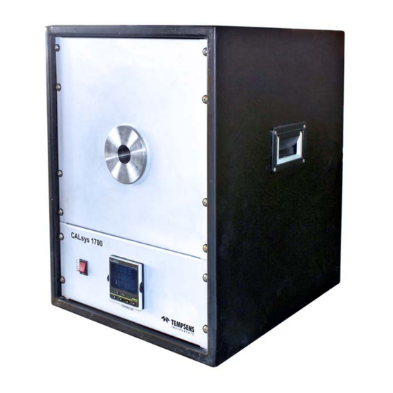
Summary of Contents for Tempsens CALsys 1700
- Page 1 Temperature Calibrator (CALsys 1700) User's Guide TEMPSENS INSTRUMENTS (l) PVT. LTD. UNIT ll A-190, Road No.5, M.I.A., Udaipur-313003 INDIA Ph. : +91-294-3500600, Fax : +91-294-3500631 Email : tech@tempsens.com Web : www.tempsens.com...
- Page 2 Legal Disclaimer The information contained in this document is the property of TEMPSENS. TEMSPENS reserves the right to make changes to this document and to the product described herein without notice. Before installing and using the product, review the latest version of the applicable documentation, which are available from the Tempsens website at: http://www.tempsens.com/...
-
Page 3: Table Of Contents
1.2 Basic Working Model of CALsys 1700..................10 1.3 Physical Measurements......................11 1.4 Wiring Diagram........................12 1.5 Technical Specifications for CALsys 1700 BB ................. 13 1.6 Technical Specifications for CALsys 1700L ................14 Chapter 2 Setting Up CALsys 1700......................... 15 2.1 Installation.......................... - Page 4 7.3 Replace Solid State Relay......................28 Chapter 8 Troubleshooting CALsys 1700......................30 8.1 CALsys 1700 unit does not turn on..................30 8.2 CALsys 1700 unit is not stable....................30 8.3 The temperature of the calibrator does not rise..............30 Page | 3...
- Page 5 Appendix A : Calibration Services ....................31 In House Calibration Facility....................31 On-site Calibration Facility...................... 32 Fixed-Point Calibration Facility....................32 Appendix B : Warranty ......................... 33 Limit of Liability........................33 Caution in Using the Product....................33 Page | 4...
-
Page 6: Preface
Preface Welcome to the Temperature Calibrator (CALsys 1700) user guide. This guide provides detailed information about all the product options and features, and explains how to use the product and configure basic settings to suit your requirements. This user manual contains information about the product and its proper use and should be kept in a place where it will be easy to access. -
Page 7: Electrical Safety
Electrical Safety WARNING: Before using this equipment, make sure it is properly grounded. Make sure the ground conductor wire (colored green/yellow) in the main power cable is connected to a protective earth/ground. If the equipment is not properly grounded, the high voltage may flow through the equipment body (chassis). -
Page 8: Health And Safety Instructions
After use, do not return the apparatus to its carrying case until the unit has cooled down. There are no user serviceable parts inside. When required, contact Tempsens agent for repair. Ensure all materials, especially flammable materials are kept away from the hot parts of the apparatus, to prevent fire risk. -
Page 9: Cautions And Preventions
Cautions and Preventions To avoid possible damage to the instrument, follow these guidelines: Before working inside the equipment, turn the power off and disconnect the power cord. DO NOT turn the unit upside down with the inserts in place; the inserts will fall out of the unit. Use of this instrument at HIGH TEMPERATURES for extended periods of time requires caution. -
Page 10: Introduction
Introduction 1.1 About CALsys 1700 The CALsys 1700 used as calibrator for thermocouple calibration and it can be also used as a pyrometer calibration with ceramic cavity. The 'CALsys 1700' has been designed to provide stable and accurate temperature to enable professionals to calibrate Temperature Sensing Devices (Thermocouple &... -
Page 11: Basic Working Model Of Calsys 1700
1.2 Basic Working Model of CALsys 1700 CALsys 1700' is a transportable unit designed for use on any reasonable flat surface. The target is a ridged Ceramic Tube Cavity which is painted by a high emissive paint .The target is heated by MoSi heaters which allow the source to heat up to 1700°C in about 3Hrs and hold it stable at temperature within ±2.0°C. -
Page 12: Physical Measurements
1.3 Physical Measurement Front View Back View Section A-A Side View Page | 11... -
Page 13: Wiring Diagram
1.4 Wiring Diagram Refer to following figure for CALsys 1700 wiring diagram. Page | 12... -
Page 14: Technical Specifications For Calsys 1700 Bb
1.5 Technical Specification CALsys 1700 has the following technical specifications: PARAMETER SPECIFICATION Voltage 230 V AC±10 Power 3 KW Supply Frequency 50/60 Hz Temperature Range 500°C to 1700°C Resolution 0.1°C Stability ±1.5°C Uniformity ±2.0°C Controlling sensor Precision B type T\C Time to reach max. -
Page 15: Technical Specifications For Calsys 1700L
1.5 Technical Specification CALsys 1700L has the following technical specifications: Temperature range 500 °C to 1700 °C ±0.5°C at 500°C Stability ±1.0°C at 1000°C ±1.5°C at 1700°C ±0.6°C at 500°C Radial uniformity ±1.4°C at 1000°C ±1.9°C at 1700°C Stabilization time 15 to 20mins Controlling sensor B type duplex... -
Page 16: Setting Up Calsys 1700
Chapter 2 Setting up CALsys 1700 2.1 Installation Place the calibrator on a flat surface with at least 10 inches of free space around the instrument. Overhead clearance is required. DO NOT Place this unit under a cabinet or structure. Plug the power cord into a grounded mains outlet located on the controlling unit rear panel. -
Page 17: Unpacking And Initial Inspection
CALsys 1700 is packed in custom-designed packaging to send out your unit. Unpack the furnace carefully. Inspect the unit after unpacking for any signs of damage, and confirm that your delivery is in accordance with the packing note. If you find any damage to the unit or an item is missing, notify Tempsens immediately. -
Page 18: Operating Instructions
2. Take out the temperature calibrator unit carefully and keep it at suitable place. 3. Install inner chamber as instructed in Installation of CALsys 1700 Chapter -3 of this user guide. 4. Connect the power plug to the mains. -
Page 19: Operating Calsys 1700
Chapter 4 Operating CALsys 1700 4.1 Turning ON the unit Plug the CALsys 1700L power cord into mains outlet of the proper voltage, frequency and current capability. Typically this will be (230 VAC±10, 50/60 Hz). Using the “ON/OFF” (for heater supply) switch located at front side responsible for heating of furnace. -
Page 20: Heating Up The Source
4.2 Heating up the source Press “UP” or “DOWN” key of controller to change the set-point value. When the set-point temperature is changed the controller will switch the furnace heater on or off to raise or lower the temperature. The displayed temperature will gradually change until it reaches the set-point temperature. -
Page 21: Cooling Down The Source
Take the reading of sensors (master and test) at stable temperature with the help of digital multi-meter, or by using Tempsens' TEMPMET 08 or TEMPMET 09 for reading RTD or TC sensor. 4.4 Cooling Down the Source Before transporting the ceramic block, ensure that the temperature of black body has cooled sufficiently. -
Page 22: Operating Unit Controller
Chapter 5 Operating Unit Controller 5.1 Operation Of controller Plug the CALsys 1700L power cord into mains outlet of the proper voltage, frequency and current capability. Typically this will be (230 VAC±10, 50/60 Hz). Using the “ON/OFF” (for heater supply) switch located at front side responsible for heating of furnace. -
Page 23: Wiring Layout Of Controller
5.2 Wiring Layout of Controller Page | 22... -
Page 24: The Temperature Controller
5.3 The Temperature Controller The upper display of the controller indicates the measured temperature, the middle display indicates the desired temperature or set point and lower display shows output power demand. 5.4 Altering the Set point To change the set point of the controller simply use the UP and DOWN keys to raise and lower the set point to the required value. -
Page 25: Digital Communication
Chapter 6 Digital Communication Digital Communication allows the controller to communicate with a PC or a networked computer system through RS-232 (or EIA232) protocol. RS-232 (or EIA232) is a standard communication protocol for linking computer and its peripheral devices to allow serial data exchange. RS-232 communication is not available if Remote Set point is fitted. -
Page 26: Digital Communications Parameters
6.2 Digital Communications Parameters The following table shows the available parameters. IGITAL OMMUNICATION COMMS CCESS CROLLING ISPLAY ARAMETER ESCRIPTION ALUE EFAULT EVEL O MODULE FITTED R232 R 232 M ODBUS INTERFACE R485 EIA485 M ODBUS INTERFACE S ORDER MODULE IDENTITY C OMMUNICATION DENTITY EIA422 M... -
Page 27: Software Installation
Chapter 7 Software Installation The provided Tempsens software offers possibilities to connect furnace temperature bath and change set point, maximum time span, view real time graph and evaluate measuring data. 7.1 Installation Install the calibration software using the installation guide file. After installing the software, start the application. - Page 28 To set the temperature of furnace as per your requirement, type the required temperature in Set Point (°C) field, and click Set. PVI Value displays the current present value of furnace temperature. The Scale Trend section enables you to configure Y-Axis Min (minimum value: 0), Y-Axis Max (maximum value: 1500), Maximum Time Span of data logging up to 120 minutes, and then click the Start Graph button.
-
Page 29: Service & Maintenance
Chapter 8 Service & Maintenance 8.1 Routine Service Turn the electricity supply off before attempting any cleaning operation. The only moving part is the fan. That has sealed-for-life bearings. Depending on the environment in which it is used, periodic cleaning is recommended. - Page 30 If the mains supply cord becomes damaged, replace it with a cord with the appropriate gauge wire for the current of the instrument. If there are any questions, contact tempsens. Page | 29...
-
Page 31: Troubleshooting Calsys 1700
9.1 CALsys 1700 unit does not turn on If the CALsys 1700 unit does not turn on or operate as usual, check if the fuse is broken, and replace the fuse if necessary. If the fuse breaks repeatedly, contact Tempsens for technical support. -
Page 32: Appendix A: Calibration Services
Appendix A: Calibration Services Tempsens Calibration Center is an independent unit of Tempsens instruments (I) Pvt. Ltd, having laboratories at Udaipur, Vadodara & Bangalore. It is accredited for wide range of temperature calibration services. It is the only private sector Laboratory in the country with accredited Fixed Point Temperature Calibration Facilities. -
Page 33: On-Site Calibration Facility
On-site Calibration Facility & M ALIBRATION EASUREMENT UALITY EASURED NSTRUMENTS EMPERATURE ANGE APABILITY Contact Type RTD, Thermocouples -25°C to 0°C 0.07°C Thermometers >0°C to 140°C 0.04°C >140°C to 250°C 0.09°C >250°C to 650°C 0.12°C >650°C to 1200°C 1.30°C Non-Contact Type Pyrometer 0°C to 250°C 1.50°C >250°C to 500°C... -
Page 34: Appendix B: Warranty
INTERFERENCE WITH OR FAILURE TO PROPERLY MAINTAIN THIS INSTRUMENT MAY INVALIDATE THIS GUARANTEE Limit of Liability TEMPSENS is not liable for any damages that arise from the use of any examples or processes mentioned in these Specifications are subject to change without notice. Caution in Using the Product TEMPSENS PRODUCTS ARE INTENDED FOR USE BY TECHNICALLY TRAINED AND COMPETENT PERSONNEL FAMILIAR WITH GOOD MEASUREMENT PRACTICES. - Page 35 TEMPSENS INSTRUMENTS (l) PVT. LTD. Tempsens Instruments (l) Pvt. Ltd. U# l B-188A, Road No.5, M.I.A., Udaipur-313003 (Rajsthan) INDIA Ph. : +91-294-3507700, Fax : +91-294-3507731 Email : info@tempsens.com...