Table of Contents
Advertisement
Quick Links
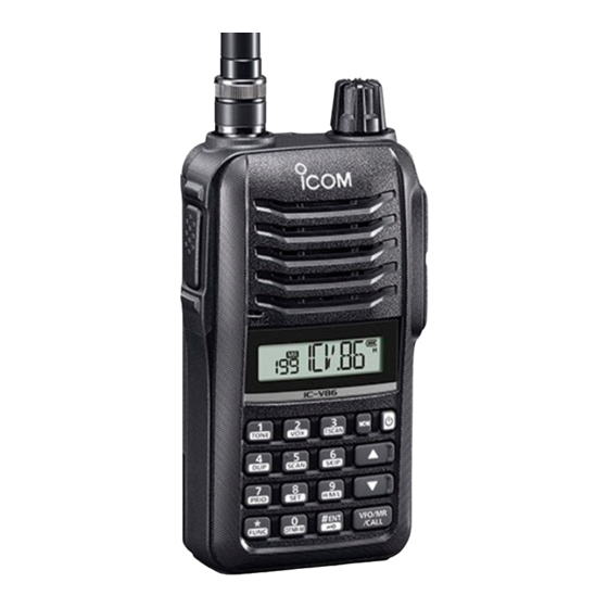
iV86/iV86-T/iG86
NOTE: Use these amended pages as one addendum set.
Do not mix them up with the previous master pages.
Replacement page
Addendum page
Amended page
Page number information
The number of revisions can be easily understood by the addendum service manual's page number.
The number of revisions (a, b, c, ...) is added after the page number.
CONTENTS
SECTION 4
SECTION 5
SECTION 6
SECTION 7
SECTION 8
[Version List]
Model
Version
USA-01
IC-V86
IC-V86
EXP-01
EXP-03
IC-V86
IC-V86-T THA-01
EXP-01
IC-G86
February 2021
SERVICE MANUAL
ADDENDUM
The page to replace the original one.
The page to be added to the original set.
The page to be added as change history, including
corrections.
ADJUSTMENT PROCEDURE �������� 4-1b~4-7b
PARTS LIST ���������������� 5-1b~5-6b
MECHANICAL PARTS ����������� 6-1b~6-2b
BOARD LAYOUTS �������������� 7-1b~7-2b
VOLTAGE DIAGRAM ������������ 8-1b~8-6b
Operable
Maximum
Version
Frequency
transmit
Number
Range
output
(MHz)
power
#11
136~174
7.0 W
#12
136~174
7.0 W
#13
136~174
7.0 W
#31
144~147
5.0 W
#41
136~174
7.0 W
Definitions
Installed unit
Remarks
-
-
-
-
-
Advertisement
Chapters
Table of Contents

Related Manuals for Icom iV86


Summary of Contents for Icom iV86
-
Page 1: Table Of Contents
February 2021 SERVICE MANUAL ADDENDUM iV86/iV86-T/iG86 NOTE: Use these amended pages as one addendum set. Do not mix them up with the previous master pages. Definitions Replacement page The page to replace the original one. Addendum page The page to be added to the original set. -
Page 2: Adjustment Procedure
(Amended page) February 2021 SECTION 4 ADJUSTMENT PROCEDURE The underlined parts have been updated from the previous version of the addendum, or from the original page. NOTE: For products with early serial numbers Refer to the first edition of the IC-V86/V86-T service manual (published in April 2019) for the adjustment procedures. - Page 3 (Amended page) February 2021 The underlined parts have been updated from the previous version of the addendum, or from the original page. JIG [JIG battery case] Ammeter DC power supply (0 to 10 A) (7.5 V/3 A) BP-263 3 A fuses Black Make two holes in the back of the case and pass the cables through.
- Page 4 (Amended page) February 2021 The underlined parts have been updated from the previous version of the addendum, or from the original page. ENTERING THE ADJUST MODE KEY ASSIGNMENTS FOR THE ADJUST MODE 1. Turn OFF the power. • Push [▲] to select the next adjustment item, push [▼] to 2.
- Page 5 (Amended page) February 2021 The underlined parts have been updated from the previous version of the addendum, or from the original page. 4-2 TRANSMIT ADJUSTMENTS ADJUSTMENT ITEM ADJUSTMENT SETTING CONDITION OPERATION DISPLAY 145.999635 ~ 146.000365 MHz FREQUENCY • Connect the RF power meter or -Verification- the dummy load to the antenna (If out of the specified range,...
- Page 6 (Amended page) February 2021 The underlined parts have been updated from the previous version of the addendum, or from the original page. 4-2 TRANSMIT ADJUSTMENTS (CONTINUED) ADJUSTMENT ITEM ADJUSTMENT SETTING CONDITION OPERATION DISPLAY TRANSMIT • Connect the RF power meter to the 4.5~6.5 W OUTPUT POWER antenna connector.
- Page 7 (Amended page) February 2021 The underlined parts have been updated from the previous version of the addendum, or from the original page. 4-2 TRANSMIT ADJUSTMENTS (CONTINUED) ADJUSTMENT ITEM ADJUSTMENT SETTING CONDITION OPERATION DISPLAY MODULATION • Connect the modulation analyzer to 10.0~20.0 mV SENSITIVITY the antenna connector through the...
- Page 8 (Amended page) February 2021 The underlined parts have been updated from the previous version of the addendum, or from the original page. 4-3 RECEIVE ADJUSTMENTS ADJUSTMENT ITEM ADJUSTMENT SETTING CONDITION OPERATION DISPLAY NOISE SQUELCH • Connect the standard signal Push [# ENT]•[ -Adjustment- generator (SSG) to the antenna (Automatic adjustment)
-
Page 9: Parts List
(Amended page) February 2021 SECTION § SECTION § SECTION 5 PARTS LIST PARTS LIST The underlined parts have been updated from the previous version of the addendum, or from the original page. [MAIN UNIT] (for IC-V86 and IC-V86-T) PART PART DESCRIPTION DESCRIPTION LOCATION... - Page 10 (Amended page) February 2021 The underlined parts have been updated from the previous version of the addendum, or from the original page. [MAIN UNIT] (for IC-V86 and IC-V86-T) PART PART DESCRIPTION DESCRIPTION LOCATION LOCATION R733 7030016030 S.RES RMC1/16S-154JTH (150 k) 34.8/37.4 C113 4030022140 S.CER GRM033B31H102KA12D...
- Page 11 (Amended page) February 2021 The underlined parts have been updated from the previous version of the addendum, or from the original page. [MAIN UNIT] (for IC-V86 and IC-V86-T) PART DESCRIPTION LOCATION C798 4030022260 S.CER GRM033R60J105MEA2D 40.3/40.2 C799 4030022260 S.CER GRM033R60J105MEA2D 39.0/35.7 C800 4030022160 S.CER GRM033B31A104KE84D...
- Page 12 (Amended page) February 2021 The underlined parts have been updated from the previous version of the addendum, or from the original page. [MAIN-A UNIT] (for IC-G86) PART PART DESCRIPTION DESCRIPTION LOCATION LOCATION 1110007010 S.IC NJM12904R-TE1 34.7/29.4 7030017370 S.RES RGC1/16SC183DTH (18 k) 31.5/28.0 1110010000 S.IC AT1846S...
- Page 13 (Amended page) February 2021 The underlined parts have been updated from the previous version of the addendum, or from the original page. [MAIN-A UNIT] (for IC-G86) PART PART DESCRIPTION DESCRIPTION LOCATION LOCATION R780 7030016110 S.RES RMC1/16S-473JTH (47 k) 33.8/37.4 C416 4030025350 S.CER GRM0332C1H120JA01D 81.7/9.5 R781...
- Page 14 (Amended page) February 2021 The underlined parts have been updated from the previous version of the addendum, or from the original page. [MAIN-A UNIT] (for IC-G86) PART DESCRIPTION LOCATION J700 6450000131 CON HSJ1102-018540 J701 6450002530 CON HSJ4456-010320 DS400 5030004550 LCD GP11538A6 DS401 5040003500 S.LED HT-191 UYG-K828...
- Page 15 (Amended page) February 2021 SECTION 6 MECHANICAL PARTS The underlined parts have been updated from the previous version of the addendum, or from the original page. [CHASSIS PARTS] [ACCESSORIES] PART PART DESCRIPTION QTY. DESCRIPTION QTY. 6510032950 BNC-R4066 – FA-B57V † [#11] †...
- Page 16 The underlined parts have been updated from the previous version of the addendum, or from the original page. Apply the glue to the following area ( MP28 (CHASSIS) (8850003421) Used glue: SL320W KONISHI (8950009140) Tighten with: ICOM DRIVER (Y)-1 (8960000461) J1 (CHASSIS) Torque: 1.5N·m (±0.15 N·m) (6510032950) J1 (CHASSIS) (6510032950)
- Page 17 (Amended page) February 2021 The underlined parts have been updated from the previous version of the addendum, or from the original page. SECTION 7 BOARD LAYOUTS The serial numbers of transceivers that use the PCB (B-9067C). Version Model Name Serial Numbers •...
- Page 18 (Amended page) February 2021 The underlined parts have been updated from the previous version of the addendum, or from the original page. • MAIN/MAIN-A UNIT (B-9067C: BOTTOM VIEW) [PTT] H100 H100 J700 J701 [MIC] [SP] NOTE: Some parts may not be mounted on the PCB. See the PARTS LIST H/V location on the PARTS LIST for location details.
- Page 19 (Amended page) February 2021 The underlined parts have been updated from the previous version of the addendum, or from the original page. SECTION 8 SCHEMATIC DIAGRAM • MAIN UNIT (for IC-V86 and IC-V86-T) (1/3) +3.3V +3.3V +3.3V +3.3V +3.3V +3.3V +3.3V MAIN UNIT (3/3)
- Page 20 (Amended page) February 2021 The underlined parts have been updated from the previous version of the addendum, or from the original page. • MAIN UNIT (for IC-V86 and IC-V86-T) (2/3) +3.3V +3.3V +3.3V +3.3V +3.3V +3.3V POSW ATSDA DS401 DS402 CLONE ATSCK ATCTS...
- Page 21 (Amended page) February 2021 The underlined parts have been updated from the previous version of the addendum, or from the original page. • MAIN UNIT (for IC-V86 and IC-V86-T) (3/3) +3.3V +3.3V +3.3V +3.3V +3.3V MAIN UNIT (1/3) MICIN POSW CP700 Battery + CP06S...
- Page 22 (Amended page) February 2021 The underlined parts have been updated from the previous version of the addendum, or from the original page. • MAIN-A UNIT (for IC-G86) (1/3) MAIN-A UNIT +3.3V +3.3V +3.3V +3.3V +3.3V +3.3V +3.3V (3/3) ATSDA MICIN ATSCK 0.15 MAIN-A UNIT...
- Page 23 (Amended page) February 2021 The underlined parts have been updated from the previous version of the addendum, or from the original page. • MAIN-A UNIT (for IC-G86) (2/3) +3.3V +3.3V +3.3V +3.3V +3.3V +3.3V +3.3V POSW ATSDA CLONE DS401 DS402 ATSCK MAIN-A UNIT BUFFER...
- Page 24 (Amended page) February 2021 The underlined parts have been updated from the previous version of the addendum, or from the original page. • MAIN-A UNIT (for IC-G86) (3/3) +3.3V +3.3V +3.3V +3.3V +3.3V MAIN-A UNIT (1/3) MICIN POSW Battery + CP700 CP06S +3.3V...
- Page 25 April 2020 SERVICE MANUAL ADDENDUM iV86/iV86-T/iG86 NOTE: Use these amended pages as one addendum set. Do not mix them up with the previous master pages. Definitions Replacement page The page to replace the original one. Addendum page The page to be added to the original set.
- Page 26 −20°C~+60°C (−4°F~+140°F) Usable temperature range ±2.5 ppm (−20°C~+60°C) Frequency stability Power supply Specified Icom's battery packs and case only 7.5 V DC (negative ground) Current drain (at 7.5 V DC) RX Internal speaker 450 mA typical (Maximum audio) External speaker 200 mA typical (Maximum audio) −...
- Page 27 (Amended page) April 2020 SECTION § SECTION 5 PARTS LIST PARTS LIST The underlined parts have been updated from the previous version of the addendum, or from the original page. [MAIN UNIT] (for IC-V86 and IC-V86-T) [MAIN UNIT] (for IC-V86 and IC-V86-T) PART PART DESCRIPTION...
- Page 28 (Amended page) April 2020 The underlined parts have been updated from the previous version of the addendum, or from the original page. [MAIN UNIT] (for IC-V86 and IC-V86-T) [MAIN UNIT] (for IC-V86 and IC-V86-T) PART PART DESCRIPTION DESCRIPTION LOCATION LOCATION R735 7030016050 S.RES RMC1/16S-102JTH (1 k)
- Page 29 (Amended page) April 2020 The underlined parts have been updated from the previous version of the addendum, or from the original page. [MAIN UNIT] (for IC-V86 and IC-V86-T) PART DESCRIPTION LOCATION C808 4030022260 S.CER GRM033R60J105MEA2D 41.2/46.0 C809 4030022260 S.CER GRM033R60J105MEA2D 39.0/36.3 C810 4030022260 S.CER GRM033R60J105MEA2D...
- Page 30 (Addendum page) April 2020 The underlined parts have been updated from the previous version of the addendum, or from the original page. [MAIN-A UNIT] (for IC-G86) [MAIN-A UNIT] (for IC-G86) PART PART DESCRIPTION DESCRIPTION LOCATION LOCATION 1110007010 S.IC NJM12904R-TE1-#ZZZB 34.7/29.4 7030017370 S.RES RGC1/16SC183DTH (18 k) 31.5/28.0...
- Page 31 (Addendum page) April 2020 The underlined parts have been updated from the previous version of the addendum, or from the original page. [MAIN-A UNIT] (for IC-G86) [MAIN-A UNIT] (for IC-G86) PART PART DESCRIPTION DESCRIPTION LOCATION LOCATION R780 7030016110 S.RES RMC1/16S-473JTH (47 k) 33.8/37.4 C417 4030022260 S.CER GRM033R60J105MEA2D...
- Page 32 (Addendum page) April 2020 The underlined parts have been updated from the previous version of the addendum, or from the original page. [MAIN-A UNIT] (for IC-G86) PART DESCRIPTION LOCATION DS401 5040003500 S.LED HT-191 UYG-K828 52.8/4.6 DS402 5040003500 S.LED HT-191 UYG-K828 48.3/4.6 MC700 7700003280 S.MIC SPU0410HR5H-PB-7...
-
Page 33: Mechanical Parts
(Amended page) April 2020 SECTION 6 MECHANICAL PARTS The underlined parts have been updated from the previous version of the addendum, or from the original page. [CHASSIS UNIT] [SUPPLIED ACCESSORIES] PART PARTS DESCRIPTION QTY. DESCRIPTION QTY. † 6510032950 BNC-R4066 – FA-B57V [#11] –... - Page 34 The underlined parts have been updated from the previous version of the addendum, or from the original page. MP28 (CHASSIS) (8850003421) Apply the grease to the following area of the front panel Tightening with: Grease type: G501 (80G) SHINETSU (8950002750) “ICOM Driver (Y)” (8960000461) Torque: 1.5 N·m (±0.15 N·m) J1 (CHASSIS) MP11 (CHASSIS) (6510032950) (8930080280)
- Page 35 (Amended page) April 2020 The underlined parts have been updated from the previous version of the addendum, or from the original page. SECTION 7 BOARD LAYOUTS The serial numbers of transceivers that use the PCB (B-8938D). Version Model Name Serial Numbers •...
- Page 36 (Amended page) April 2020 The underlined parts have been updated from the previous version of the addendum, or from the original page. • MAIN UNIT (for IC-V86 and IC-V86-T/B-8938D: BOTTOM VIEW) [PTT] H100 J700 J701 [MIC] [SP] See the PARTS LIST H/V location on the PARTS LIST for location details. 7-2a...
- Page 37 (Amended page) April 2020 The underlined parts have been updated from the previous version of the addendum, or from the original page. The serial numbers of transceivers that use the PCB (B-8938E). Version Model Name Serial Numbers • MAIN UNIT (for IC-V86 and IC-V86-T/B-8938E: TOP VIEW) Number IC-V86 11005001 ~ 11008200...
- Page 38 (Amended page) April 2020 The underlined parts have been updated from the previous version of the addendum, or from the original page. • MAIN UNIT (for IC-V86 and IC-V86-T/B-8938E: BOTTOM VIEW) [PTT] H100 J700 J701 [MIC] [SP] See the PARTS LIST H/V location on the PARTS LIST for location details. 7-4a...
- Page 39 (Amended page) April 2020 The underlined parts have been updated from the previous version of the addendum, or from the original page. The serial numbers of transceivers that use the PCB (B-9151). Version Model Name Serial Numbers • MAIN UNIT (for IC-V86 and IC-V86-T/B-9151: TOP VIEW) Number IC-V86 11008201 ~ 11014000...
- Page 40 (Amended page) April 2020 The underlined parts have been updated from the previous version of the addendum, or from the original page. • MAIN UNIT (for IC-V86 and IC-V86-T/B-9151: BOTTOM VIEW) [PTT] H100 J700 J701 [MIC] [SP] See the PARTS LIST H/V location on the PARTS LIST for location details. 7-6a...
- Page 41 (Amended page) April 2020 The underlined parts have been updated from the previous version of the addendum, or from the original page. The serial numbers of transceivers that use the PCB (B-9151A). Version Model Name Serial Numbers • MAIN UNIT (for IC-V86 and IC-V86-T/B-9151A: TOP VIEW) Number IC-V86 11014001 and above...
- Page 42 (Amended page) April 2020 The underlined parts have been updated from the previous version of the addendum, or from the original page. • MAIN UNIT (for IC-V86 and IC-V86-T/B-9151A: BOTTOM VIEW) [PTT] H100 J700 J701 [MIC] [SP] See the PARTS LIST H/V location on the PARTS LIST for location details. 7-8a...
- Page 43 (Addendum page) April 2020 The underlined parts have been updated from the previous version of the addendum, or from the original page. • MAIN-A UNIT (for IC-G86/B-9067B: TOP VIEW) [MIC] [SP] D406 D405 D407 IC701 D708 R729 R752 R781 C745 R734 R789 C741...
- Page 44 (Addendum page) April 2020 The underlined parts have been updated from the previous version of the addendum, or from the original page. • MAIN-A UNIT (for IC-G86/B-9067B: BOTTOM VIEW) [PTT] H100 J700 J701 [MIC] [SP] See the PARTS LIST H/V location on the PARTS LIST for location details. 7-10a...
- Page 45 (Amended page) April 2020 The underlined parts have been updated from the previous version of the addendum, or from the original page. SECTION 8 VOLTAGE DIAGRAM • MAIN UNIT (for IC-V86 and IC-V86-T) (1/3) +3.3V +3.3V +3.3V MAIN UNIT +3.3V +3.3V +3.3V (3/3)
- Page 46 (Amended page) April 2020 The underlined parts have been updated from the previous version of the addendum, or from the original page. • MAIN UNIT (for IC-V86 and IC-V86-T) (2/3) +3.3V +3.3V +3.3V +3.3V +3.3V +3.3V Backlight POSW ATSDA ON : 3.5 V DS401 DS402 CLONE...
- Page 47 (Amended page) April 2020 The underlined parts have been updated from the previous version of the addendum, or from the original page. • MAIN UNIT (for IC-V86 and IC-V86-T) (3/3) +3.3V +3.3V +3.3V +3.3V +3.3V MAIN UNIT (1/3) MICIN TX : 4.9 V POSW CP700 Battery +...
- Page 48 (Addendum page) April 2020 The underlined parts have been updated from the previous version of the addendum, or from the original page. • MAIN-A UNIT (for IC-G86) (1/3) MAIN-A UNIT +3.3V +3.3V +3.3V +3.3V +3.3V +3.3V (3/3) ATSDA MICIN ATSCK 0.15 At TX output power: MAIN-A UNIT...
- Page 49 (Addendum page) April 2020 The underlined parts have been updated from the previous version of the addendum, or from the original page. • MAIN-A UNIT (for IC-G86) (2/3) +3.3V +3.3V +3.3V +3.3V +3.3V +3.3V Backlight POSW ATSDA ON : 3.5 V CLONE DS401 DS402...
- Page 50 (Addendum page) April 2020 The underlined parts have been updated from the previous version of the addendum, or from the original page. • MAIN-A UNIT (for IC-G86) (3/3) +3.3V +3.3V +3.3V +3.3V +3.3V MAIN-A UNIT (1/3) MICIN TX : 4.9 V POSW Battery + CP700...
- Page 51 SERVICE MANUAL VHF TRANSCEIVERS |V86 |V86-T S-15514XZ-C1 April 2019...
- Page 52 7. READ the instructions of the test equipment thoroughly before connecting it to the transceiver. Icom, Icom Inc. and the Icom logo are registered trademarks of Icom Incorporated (Japan) in Japan, the United States, the United Kingdom, Germany, France, Spain, Russia, Australia, New Zealand, and/or other countries.
-
Page 53: Board Layouts
TABLE OF CONTENTS SECTION 1 SPECIFICATIONS SECTION 2 INSIDE VIEWS SECTION 3 DISASSEMBLY INSTRUCTIONS SECTION 4 ADJUSTMENT PROCEDURE PREPARATION ……………………………………………………………………………………… 4-1 TRANSMIT ADJUSTMENTS ……………………………………………………………………… 4-4 RECEIVE ADJUSTMENTS ………………………………………………………………………… 4-7 SECTION 5 PARTS LIST SECTION 6 MECHANICAL PARTS SECTION 7 BOARD LAYOUTS SECTION 8 BLOCK DIAGRAM SECTION 9... -
Page 54: Specifications
−20°C~+60°C (−4°F~+140°F) Usable temperature range ±2.5 ppm (−20°C~+60°C) Frequency stability Power supply Specified Icom's battery packs and case only 7.5 V DC (negative ground) Current drain (at 7.5 V DC) RX Internal speaker 450 mA typical (Maximum audio) External speaker 200 mA typical (Maximum audio) −... -
Page 55: Inside Views
SECTION 2 INSIDE VIEWS • MAIN UNIT (TOP VIEW) ANTENNA CONNECTOR (J1: CHASSIS UNIT) +5 V REGULATOR MAIN UNIT (IC818) POWER SWITCH (Q722) AF AMPLIFIER (IC706) AF AMPLIFIER [MIC] (J700) (IC819) [SP] (J701) MICROPHONE (MC700) ALC AMPLIFIER (IC701) (DS400) - Page 56 • MAIN UNIT (BOTTOM VIEW) [VOL] (S400) [PTT] (S401) D/A CONVERTER (IC702) POWER AMPLIFIER AF AMPLIFIER (Q9) (IC817) DRIVER (Q7) APC AMPLIFIER PRE DRIVE (IC1) (Q6) DIRECT CONVERSION IC (IC3) +3.3 V DC-DC CONVERTER Inside the shielded case. (IC707) AF MUTE SWITCH (IC820) 13 MHz REFERENCE OSCILLATOR...
-
Page 57: Disassembly Instructions
For easy separation of the CHASSIS of the front panel. Use a suction lifter to lift the bottom of the CHASSIS up. Antenna nut Volume knob Remove with; “ICOM Driver (K)” (8960000113) Suction lifter • Part name: EA950R-2 • Manufacture: ESCO CO.LTD... - Page 58 2) Remove the top seal and volume nut from the top of the 4) Remove the 2 screws from the heatsink of MAIN UNIT. chassis. Screws ×2 Top seal Volume nut Remove with; “ICOM Driver (AG)” (8960000561) MAIN UNIT Chassis Heatsink 5) Remove the side plate from the chassis. Side plate Chassis 3) Remove the 7 screws from the MAIN UNIT.
-
Page 59: Adjustment Procedure
SECTION 4 ADJUSTMENT PROCEDURE 4-1 PREPARATION ■ REQUIRED EQUIPMENT EQUIPMENT GRADE AND RANGE EQUIPMENT GRADE AND RANGE Output voltage: 7.5 V Modified BP-263. DC power supply JIG battery case Current capacity: 3 A or more (See the illustration shown on page 4-2.) Modified 3.5 mm (⅛... - Page 60 ■ JIG [JIG battery case] Ammeter DC power supply (0 to 10 A) (7.5 V/3 A) BP-263 Black Make two holes in the back of the case and pass the cables through. [JIG plug] (GND) 3-conductor 3.5 (d) mm (¹⁄8 in) plug 82 kΩ...
- Page 61 ■ ENTERING THE ADJUST MODE ■ KEY ASSIGNMENTS FOR THE ADJUST MODE 1. Turn OFF the power. • Push [▲] to select the next adjustment item, push [▼] to 2. Connect the JIG plug to the [SP] connector. select the previous adjustment item. •...
-
Page 62: Transmit Adjustments
4-2 TRANSMIT ADJUSTMENTS ADJUSTMENT ITEM ADJUSTMENT SETTING CONDITION OPERATION DISPLAY FREQUENCY • Connect the RF power meter or 146.000 MHz ±365 Hz -Verification- the dummy load to the antenna (If out of the specified range, connector. adjust the frequency by [VOL], •... - Page 63 4-2 TRANSMIT ADJUSTMENTS (CONTINUED) ADJUSTMENT ITEM ADJUSTMENT SETTING CONDITION OPERATION DISPLAY TRANSMIT • Connect the RF power meter to the 4.5~6.5 W OUTPUT POWER antenna connector. (If out of the specified range, -Verification- • While transmitting, adjust the adjust the output power by [VOL], (Extra High) connected DC power supply then push [# ENT]•[...
- Page 64 4-2 TRANSMIT ADJUSTMENTS (CONTINUED) ADJUSTMENT ITEM ADJUSTMENT SETTING CONDITION OPERATION DISPLAY MODULATION • Connect the modulation analyzer to 10.0~20.0 mV SENSITIVITY the antenna connector through the (Audio generator output level) -Verification- attenuator and set it to: HPF: LPF: 20 kHz or 15 kHz De-emphasis: OFF Detector: (P−P)/2...
-
Page 65: Receive Adjustments
4-3 RECEIVE ADJUSTMENTS ADJUSTMENT ITEM ADJUSTMENT SETTING CONDITION OPERATION DISPLAY NOISE SQUELCH • Connect the standard signal Push [# ENT]•[ -Adjustment- generator (SSG) to the antenna (Automatic adjustment) connector and set it to: Frequency: 146.020 MHz Modulation: 1 kHz Deviation: ±1.5 kHz −17 dBµ... -
Page 66: Parts List
SECTION 5 PARTS LIST [MAIN UNIT] [MAIN UNIT] PART PART DESCRIPTION DESCRIPTION LOCATION LOCATION 1110007010 S.IC NJM12904R-TE1-#ZZZB 34.7/29.4 7030015520 S.RES RMC1/16JPTP 65.4/9.2 1110010000 S.IC AT1846S 47.4/16.1 7030016550 S.RES RMC1/16SK154FTH (150 k) 31.5/26.4 IC400 1130019660 S.IC BR24G128NUX-5TR 92.2/14.0 7030016560 S.RES RMC1/16SJPTH 61.5/10.5 IC402 1140018490 S.IC... - Page 67 [MAIN UNIT] [MAIN UNIT] PARTS PARTS DESCRIPTION DESCRIPTION LOCATION LOCATION R753 7030016020 S.RES RMC1/16S-104JTH (100 k) 17.7/37.4 C420 4030022260 S.CER GRM033R60J105MEA2D 77.3/10.9 R759 7030015970 S.RES RMC1/16S-103JTH (10 k) 47.1/42.1 C421 4030022160 S.CER GRM033B31A104KE84D 77.3/11.5 R762 7030016810 S.RES RGC1/16SC392DTH (3.90 k) 50.9/43.5 C425 4030025400 S.CER GRM033R61A273KE84D...
- Page 68 [MAIN UNIT] PARTS DESCRIPTION LOCATION S400 2250001090 ENC ED08902OFK150S070C-2015 S401 2260003490 S.SWI TAFG-12W-QR 17.4/1.9 8930101610 LCD SRCN-4066-SP-N-W (SHJ) 6910018460 S.BEA MMZ1005Y102C-T 33.3/9.5 6910014690 S.BEA MPZ1608S221A-T 24.5/20.0 EP400 6910021240 S.BEA MMZ1005A152ET 78.9/38.3 EP700 6910018460 S.BEA MMZ1005Y102C-T 24.0/45.6 EP701 6910018460 S.BEA MMZ1005Y102C-T 18.7/45.5 EP702 6910019900 S.BEA MPZ1608S601AT...
- Page 69 SECTION 6 MECHANICAL PARTS [CHASSIS UNIT] [ACCESSORIES] PART PARTS DESCRIPTION QTY. DESCRIPTION QTY. − FA-B57V 6510032950 BNC-R4066 † [#11] − FA-B45V † [#12] − FA-B57V † [#13] − FA-B45V † 8010021713 3285 CHASSIS-3 [#31] − BP-298 8930079900 3285 TERMINAL HOLDER †...
- Page 70 MP28 (CHASSIS) (8850003421) Apply the grease to the following area of the front panel Tightening with: Used grease: G501 (80G) SHINETSU (8950002750) “ICOM Driver (Y)” (8960000461) Torque: 1.5 N·m (±0.15 N·m) J1 (CHASSIS) MP11 (CHASSIS) (6510032950) (8930080280) MP2 (CHASSIS) (8930079900)
- Page 71 SECTION 7 BOARD LAYOUTS The actual configuration of the PC board can be seen by viewing the top and bottom BOARD LAYOUT pages together. • MAIN UNIT (B-8938C: TOP VIEW) [MIC] [SP] D406 D405 D407 IC701 R729 R781 R789 C745 R734 C741 Q718...
- Page 72 The actual configuration of the PC board can be seen by viewing the top and bottom BOARD LAYOUT pages together. • MAIN UNIT (B-8938C: BOTTOM VIEW) [SP] [MIC] J701 J700 Q703 R769 EP701 C759 R767 R712 Q716 C811 R763 R762 R773 R785 EP702...
- Page 73 SECTION 8 BLOCK DIAGRAM 136~174MHz MAIN UNIT J700 Q703 +3.3V Current [MIC] XPTT +3.3V D6~D9, IC817, D705,D706 DRIVE TCXO DRIVE MIC1,MIC2 VOXV 13.00MHz IC701 Q721 IC701 Direct Conversion MIC GAIN MICIN IC1,Q10 MC700 CTRL Q704 RFPWR AUTO_TX CTRL Q2,Q4, MUTE TMUT IC820 RMUT...
- Page 74 SECTION 9 VOLTAGE DIAGRAM • MAIN UNIT (1/3) +3.3V +3.3V +3.3V MAIN UNIT (3/3) ATSDA MICIN ATSCK 0.15 ATCTS MAIN UNIT TEMPERATURE ATSQ (2/3) ATDTMF TEMP At TX output power: TMUT 470k Extra high: 0.7 V RFPWR High: 0.5 V TEMP Middle: 0.3 V...
- Page 75 • MAIN UNIT (2/3) +3.3V +3.3V +3.3V Backlight POSW ATSDA ON : 3.5 V DS401 DS402 CLONE ATSCK ATCTS OFF : 4.6 V BUFFER MAIN UNIT PWON ATSQ (1/3) ATDTMF LIGT HT-191UYG HT-191UYG R428 MDET Q400 Backlight 2SC4116 TMUT Backlight RFPWR ON : 1.5 V D413...
- Page 76 • MAIN UNIT (3/3) +3.3V +3.3V MAIN UNIT (1/3) MICIN TX : 4.9 V POSW CP700 Battery + 5.0 V RX : 0 V 7.5 V 3.4 V CP06S +3.3V PWON Battery monitor When the Power Save function is ON: 5.0 V BATV Battery −...
- Page 77 If you have any inquiries regarding service, contact your distributor. The contact number or E-mail address of your distributor can be found on our website. https://www.icomjapan.com/...
- Page 78 S-15514XZ-C1 1-1-32, Kamiminami, Hirano-ku, Osaka 547-0003, Japan © 2019 Icom Inc.