Icom IC-746PRO Instruction Manual
Hf/vhf all mode transceiver
Hide thumbs
Also See for IC-746PRO:
- Manual (164 pages) ,
- Instruction manual (116 pages) ,
- Service manual (7 pages)
Table of Contents
Advertisement
INSTRUCTION MANUAL
HF/VHF
ALL MODE TRANSCEIVER
i746PRO
This device complies with Part 15 of the FCC rules. Operation is sub-
ject to the following two conditions: (1) This device may not cause
harmful interference, and (2) this device must accept any interference
received, including interference that may cause undesired operation.
Advertisement
Table of Contents

Related Manuals for Icom IC-746PRO


Summary of Contents for Icom IC-746PRO
-
Page 1: Instruction Manual
INSTRUCTION MANUAL HF/VHF ALL MODE TRANSCEIVER i746PRO This device complies with Part 15 of the FCC rules. Operation is sub- ject to the following two conditions: (1) This device may not cause harmful interference, and (2) this device must accept any interference received, including interference that may cause undesired operation. -
Page 2: Explicit Definitions
RF exposure and safety standards your IC-746PRO your radio of choice, and hope you please refer to the Federal Communications Commission agree with Icom’s philosophy of “technology first”.Many Office of Engineering and Technology’s report on Evalu-... -
Page 3: Table Of Contents
Spare fuse (FGB 5 A) ........1 t CW keyer plug (AP-330) ........1 Icom, Icom Inc. and the are registered trademarks of Icom Incorporated (Japan) in the United States, the United King- dom, Germany, France, Spain, Russia and/or other countries. -
Page 4: Quick Reference Guide
12 V DC. the appropriate color coded terminals, then insert the DC connector into the DC jack located on the rear of The perfect match to your IC-746PRO is the PS-125. the radio. This compact switching power supply is the matching... - Page 5 There are three connections on range and SWR may be increased out-of-range. the back of your IC-746PRO, two for HF and 6 m and When the SWR is higher than approx. 2.0:1, the one for 2 m. If you are using one antenna for HF and transceiver’s power drops to protect the final tran-...
-
Page 6: Operation
If you do not see the particular item you are wanting the time to connect this gear! We will cover the basic to connect, refer to the Advance Connections section devices that can be connected to your IC-746PRO. starting on page 15. Operation 1. -
Page 7: Your First Contact
HEADPHONES SP-21 (optional) Your first contact Now you should have your IC-746PRO installed in your shack, and like a kid on his birthday, you are probably excited to get on the air. We would like to take you through a few basic operation steps to make your first “On The Air”... - Page 8 1. Select the desired band • Say you want to go to 20 meters or 14 MHz; you Your IC-746PRO easy way of changing bands using would push the [14 5]. This will immediately change the keypad located just above the tuning knob on the the displayed operating frequency to the 20-meter right hand side of the display.
- Page 9 Decreases Increases a. Noise Reduction: The noise reduction system on your IC-746PRO is part of the 32-bit DSP. This is used to reduce the hiss and QRM levels. To acti- vate, push the [NR] switch located just to the right Noise reduction ON of the [PHONES] jack.
- Page 10 AGC from the interfering signal. d. Filters: Your IC-746PRO has an incredible IF DSP based filter network with over 100 settings. • Dial in your filters: By pushing [FILTER] for 1 sec., •...
- Page 11 QUICK REFERENCE GUIDE d. Filters:— continued PBT operation example • On the fly adjustment: Once the adjustments have [TWIN PBT] control been made in the filter set mode, you can make on the fly changes by using the Twin Pass Band Tuning, Twin PBT.
-
Page 12: Ready To Call Cq
[CW PITCH]: 12 o’clock [KEY SPEED]: Max. CCW 1. Setting up your transmit audio The 32-bit DSP in your IC-746PRO is capable of giving you the type of transmit audio for your SSB Operation. 2. Mic Gain The microphone gain is used for proper transmit quire a setting of the [MIC GAIN] you should find a audio level for full output power. - Page 13 Tone Control will give you more audio control for your Voice operation on SSB, AM, and FM modes. Your IC-746PRO is equipped with a very powerful equal- izer system with 121 possible combinations. This is achieved by using the separate bass and treble ad- justments.
-
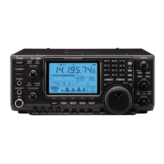
Page 14: Panel Description
PANEL DESCRIPTION Front panel ! 3 ! 2 i746PRO HF/VHF TRANSCEIVER TUNER POWER F-INP NOTCH TRANSMIT SPLIT 144 ENT GENE A /B PHONES MP-W MP-R /NOTCH LOCK ELEC-KEY RF/SQL MENU CW/RTTY AM/FM FILTER LOCK/ CALL MIC GAIN RF PWR CW PITCH KEY SPEED P.AMP/ATT VOX/BK-IN... -
Page 15: Panel Description
Set the [MIC] control so that the ALC meter sometimes swings during normal voice transmission in SSB mode. Switches the antenna connector selection between ANT1 and ANT2 when pushed. Recommended level for an Icom microphone !5 NOISE REDUCTION LEVEL CONTROL [NR] (inner control; p. 53) Decreases Increases... - Page 16 PANEL DESCRIPTION Front panel (continued) i746PRO TWIN PBT HF/VHF TRANSCEIVER TUNER F-INP NOTCH SPLIT PBTC 144 ENT GENE A /B V / M M-CL M-CH MP - W MP - R /NOTCH LOCK RF/SQL ∂TX CLEAR RIT/∂TX MENU CW/RTTY AM/FM FILTER LOCK/ CALL...
- Page 17 PANEL DESCRIPTION @3 VOX/BREAK-IN SWITCH [VOX/BK-IN] #0 RIT SWITCH [RIT] (p. 48) In SSB, AM and FM modes, push momentarily to Turns the RIT function ON and OFF when pushed. • Use the [RIT/∂TX] control to vary the RIT frequency. turn the VOX function ON and OFF (p.
- Page 18 PANEL DESCRIPTION Front panel (continued) % 0 $ 9 $ 8 i746PRO TWIN PBT HF/VHF TRANSCEIVER F-INP NOTCH SPLIT PBTC 144 ENT GENE A /B V / M M-CL M-CH MP - W MP - R /NOTCH LOCK RF/SQL ∂TX CLEAR RIT/∂TX MENU...
- Page 19 Turns the quick split function ON, when pushed stacked frequencies in the band. (p. 19) for 1 sec. (p. 60) • Icom’s triple band stacking register memorizes 3 fre- • The offset frequency is shifted from the displayed fre- quencies in each band.
-
Page 20: Rear Panel
DC POWER SOCKET [DC 13.8V] (pgs. 14, 16) o ALC INPUT JACK [ALC] (p. 17) Accepts 13.8 V DC through the supplied DC power Connects to the ALC output jack of a non-Icom lin- cable (OPC-025D). ear amplifier. !0 ACCESSORY SOCKET 2 [ACC(2)]... -
Page 21: D Data Socket
PANEL DESCRIPTION D DATA SOCKET DATA PIN No. NAME DESCRIPTION DATA IN Input terminal for data transmit. (1200 bps: AFSK/9600 bps: G3RUH, GMSK) Common ground for DATA IN, DATA OUT and AF OUT. PTT P PTT terminal for packet operation. Connect ground to transmit data. DATA OUT Data out terminal for 9600 bps operation only. -
Page 22: Lcd Display
PANEL DESCRIPTION LCD display q FREQUENCY READOUTS ⁄ TUNING DIAL SPEED INDICATOR (p. 21) Show the operating frequency. Appears when the tuning dial speed is set so that one rotation is equal to ⁄ of the normal rotation. w MULTI-FUNCTION METER INDICATION !1 VOICE SQUELCH CONTROL INDICATOR (p. - Page 23 PANEL DESCRIPTION LCD display (continue) !5 BREAK-IN INDICATORS (p. 56) @4 NOISE REDUCTION INDICATOR (p. 53) “F BK-IN” appears when the full break-in function Appears when the noise reduction is activated. is activated. @5 NOTCH INDICATORS (p. 53) “BK-IN” appears when the semi break-in function “NOTCH”...
-
Page 24: Multi Function Switches
PANEL DESCRIPTION Multi function switches M1 FUNCTIONS ⁄ FUNCTION (p. 21) During SSB operation Push to turn the ⁄ function ON/OFF. • “ ” indicator appears when the ⁄ function is TRANSMISSION BANDWIDTH (p. 58) Push to select the transmission bandwidth. During SSB data operation •... -
Page 25: Microphone (Hm-36)
DO NOT short pin 2 to ground as this can damage the internal 8 V regulator. NOTE: DC voltage is applied to pin 1 for micro- phone operation. Take care when using a non-Icom microphone. • HM-36 SCHEMATIC DIAGRAM MICROPHONE MICROPHONE CABLE MICROPHONE PLUG 10µ... -
Page 26: Installation And Connections
R WARNING: NEVER power for transmitting even when using the antenna connect the [GND] tuner. The IC-746PRO has an SWR meter to moni- terminal to a gas or electric pipe, since the connec- tor the antenna SWR continuously. tion could cause an explosion or electric shock. -
Page 27: Required Connections
INSTALLATION AND CONNECTIONS Required connections • Front panel CW KEY i746PRO TWIN PBT HF/VHF TRANSCEIVER TUNER POWER F-INP NOTCH TRANSMIT SPLIT PBTC GENE 144 ENT M-CL PHONES M-CH MP-W MP-R A/NOTCH ELEC-KEY RF/SQL ∂TX CLEAR (dot) (com) RIT/∂TX (dash) MENU CW/RTTY AM/FM FILTER... -
Page 28: Advanced Connections
When using the AH-4, it must be connected to the [ANT1] connector. [SEND], [ALC] (p. 17) Used for connecting a non-Icom linear ampli- fier. [DATA] (p. 77) ACC SOCKETS (pgs. 8, 77) [REMOTE] (p. 94) Used for computer control and transceive operation. -
Page 29: Power Supply Connections
• The [POWER] switch is OFF. power. Refer to the diagrams below. • Output voltage of the power source is 12–15 V when you use a non-Icom power supply. • DC power cable polarity is correct. : positive + terminal... -
Page 30: Linear Amplifier Connections
(Non-European versions: 100—120/220—240 V European version : 230 V) Turn OFF the transceiver’s antenna tuner while tuning the IC-PW1’s tuner. CONNECTING A NON-ICOM LINEAR AMPLIFIER R WARNING: 50 Ω coaxial cable Set the transceiver output power and linear To an amplifier ALC output level referring to the linear... -
Page 31: Basic Operation
BASIC OPERATION When first applying power (CPU resetting) Before first applying power, make sure all connections required for your system are complete by referring to Chapter 2. Then, reset the transceiver using the fol- lowing procedure. NOTE: When first applying power or when operat- ing in cold environments, the display may flicker or appear faint. -
Page 32: Selecting An Operating Band
BASIC OPERATION Selecting an operating band The transceiver has a triple band stacking register. Band keys This means that the last 3 operating frequencies and modes used on a particular band are automatically memorized. See the table below for a list of the bands available and the default settings for each register. -
Page 33: Selecting Vfo/Memory Mode
BASIC OPERATION Selecting VFO/memory mode [V/M] VFO is an abbreviation of Variable Frequency Oscilla- tor, and traditionally refers to an oscillator. Push [V/M] to switch between VFO and memory modes. • Pushing [V/M] for 1 sec. transfers the contents of the se- lected memory channel to VFO mode (p. -
Page 34: Frequency Setting
BASIC OPERATION Frequency setting The transceiver has several tuning methods for conve- nient frequency tuning. D Tuning with the tuning dial Band keys q Push the desired band key on the keypad 1–3 times. • 3 different frequencies can be selected on each band with the band key. -
Page 35: D Band Edge Warning Beep
BASIC OPERATION D Selecting the 1 Hz step The minimum tuning step of 1 Hz can be used for fine tuning. q Push [TS] momentarily to turn the quick tuning step • “ ” disappears. w Push [TS] for 1 sec. to toggle the 1 Hz tuning step ON and OFF. -
Page 36: Operating Mode Selection
SSB (USB/LSB), SSB data (USB data/LSB data), CW, CW reverse (CW-R), RTTY, RTTY-R (RTTY reverse), AM, AM data, FM and FM data modes are available in the IC-746PRO. Select the desired operation mode as follows. To select a mode of operation, push the desired mode switch momentarily. -
Page 37: Squelch And Receive (Rf) Sensitivity
BASIC OPERATION Squelch and receive (RF) sensitivity Adjusts the RF gain and squelch threshold level. The [RF/SQL] control squelch removes noise output from the speaker (closed position) when no signal is received. • The squelch is particularly effective for FM. It is also avail- able for other modes. -
Page 38: Basic Transmit Operation
BASIC OPERATION Basic transmit operation Before transmitting, monitor your selected oper- ating frequency to make sure transmitting won’t cause interference to other stations on the same frequency. D Transmitting Before transmitting, monitor your selected operating [TRANSMIT] [TX] indicator frequency to make sure transmitting won’t cause inter- ference to other stations on the same frequency. -
Page 39: Receive And Transmit
RECEIVE AND TRANSMIT Operating SSB [TRANSMIT] [TX] indicator Band keys q Push a band key to select the desired band. w Push [SSB] to select LSB or USB. • Below 10 MHz LSB is automatically selected; above 10 MHz USB is automatically selected. e Rotate [AF] to set audio to a comfortable listening level. -
Page 40: Operating Cw
RECEIVE AND TRANSMIT Operating CW [TRANSMIT] [TX] indicator Band keys q Push a band key to select the desired band. w Push [CW/RTTY] to select CW. • After CW mode is selected, push [CW/RTTY] for 1 sec. to toggle between CW and CW-R modes. e Rotate [AF] to set audio to a comfortable listening level. -
Page 41: D About Cw Reverse Mode
RECEIVE AND TRANSMIT D About CW reverse mode CW reverse mode receives CW signals with a reverse side CW carrier point like that of LSB and USB modes. Use this mode when interfering signals are near the Push for 1 sec. desired signal and you want to change the interference CW/RTTY tone. -
Page 42: Electronic Keyer Functions
RECEIVE AND TRANSMIT Electronic keyer functions The transceiver has a number of convenient functions for the electronic keyer that can be accessed from the memory keyer menu. q Push [CW/RTTY] to select CW mode. w Push [MENU] to select M1. e Push [F4 KEY] to select the memory keyer menu. -
Page 43: D Memory Keyer Send Menu
RECEIVE AND TRANSMIT D Memory keyer send menu Pre-set characters can be sent using the keyer send menu. Contents of the memory keyer are set using the edit menu. • Transmitting q While M1 is selected in CW mode, push [F4 KEY] to select the memory keyer menu. -
Page 44: D Editing A Memory Keyer
RECEIVE AND TRANSMIT D Editing a memory keyer The contents of the memory keyer memories can be set using the memory keyer edit menu. The memory keyer can memorize and re-transmit 4 CW key codes for often-used CW sentences, contact numbers, etc. Total capacity of the memory keyer is 50 characters per memory channel. -
Page 45: D Contest Number Set Mode
RECEIVE AND TRANSMIT D Contest number set mode This menu is used to set the contest (serial) number and count up trigger, etc. • Setting contents q Push [MENU] to select M1, then push [F4 KEY] to select the memory keyer menu. w Push [F4 001] to enter the contest number set mode. - Page 46 RECEIVE AND TRANSMIT D Keyer set mode This set mode is used to set the CW side tone, mem- ory keyer repeat time, dash weight, paddle specifica- tions, keyer type, etc. • Setting contents q Push [MENU] to select M1, then push [F4 KEY] to select the memory keyer menu.
-
Page 47: Rise Time
RECEIVE AND TRANSMIT 5. Rise Time This item set the envelop time period which the output R i s e T i m e power becomes the set transmit power. 4 m s • 2, 4, 6 or 8 msec. can be selected. •... -
Page 48: Operating Rtty (Fsk)
RECEIVE AND TRANSMIT Operating RTTY (FSK) Before operating RTTY, be sure to consult the manual that come with your TNC. q Push a band key to select the desired band. [TRANSMIT] [TX] indicator Band keys w Push [CW/RTTY] several times to select RTTY. •... -
Page 49: Rtty Functions
RECEIVE AND TRANSMIT RTTY functions The transceiver has a number of convenient functions for the RTTY operation that can be accessed from the RTTY menu. q Push [CW/RTTY] to select RTTY mode. w Push [MENU] to select M1. e Push [F4 RTY] to select the RTTY menu. r Push one of the multi-function keys ([F2], [F4] or [F5]) to select an item in the RTTY menu. - Page 50 RECEIVE AND TRANSMIT D RTTY filter/Twin peak filter The transceiver has 5 RTTY filters in addition to nor- mal IF filters. The passband width can be selected from 1 kHz, 500 Hz, 350 Hz, 300 Hz and 250 Hz. When the RTTY filter is turned ON, the RTTY tuning meter can be used.
-
Page 51: D Rtty Decoder
RECEIVE AND TRANSMIT D RTTY decoder The transceiver has an RTTY decoder for Baudot (mark freq.: 2125 Hz, shift freq.: 170 Hz, 45 bps). An external terminal unit (TU) or terminal node con- nector (TNC) is not necessary for receiving a Baudot signal. -
Page 52: Rtty Shift
RECEIVE AND TRANSMIT D RTTY set mode This set mode is used to set the mark and shift fre- quencies, keying type, decode USOS function, etc. • Setting contents q Push [MENU] to select M1, then push [F4 RTY] to select the RTTY menu. -
Page 53: Operating Am
RECEIVE AND TRANSMIT Operating AM [TRANSMIT] [TX] indicator Band keys q Push a band key to select the desired band. w Push [AM/FM] to select AM. e Rotate [AF] to set audio to a comfortable listening level. r Rotate the tuning dial to tune a desired signal. •... -
Page 54: Operating Fm
RECEIVE AND TRANSMIT Operating FM [TRANSMIT] [TX] indicator Band keys q Push a band key to select the desired band. w Push [AM/FM] to select FM. e Rotate [AF] to set audio to a comfortable listening level. r Rotate the tuning dial to tune a desired signal. •... -
Page 55: D Tone Squelch Operation
RECEIVE AND TRANSMIT D Tone squelch operation Tone squelch operation is a method of communica- tions using selective calling. Only received signal hav- ing a matching tone will open the squelch. Before communicating using tone squelch, all members of your party must agree on the tone squelch frequency to use. -
Page 56: D Dtcs Operation
RECEIVE AND TRANSMIT D DTCS operation DTCS function is an another method of communica- tions using selective calling. Only received signal hav- ing a matching 3-digit code will open the squelch. q Push [AM/FM] to select FM mode. w Push [MENU] several times to select M1. e Push [F4 TON] several times to turn the DTCS function ON. -
Page 57: Repeater Operation
RECEIVE AND TRANSMIT Repeater operation A repeater amplifies received signals and retransmits them at a different frequency. When using a repeater, the transmit frequency is shifted from the receive fre- quency by an offset frequency. A repeater can be ac- cessed using split frequency operation with the shift frequency set to the repeater’s offset frequency. -
Page 58: Memory Channels
RECEIVE AND TRANSMIT D Transmit frequency monitor check You may be able to receive the other party’s transmit signal directly without having to go through a repeater. This function allows you to check this. While receiving, push and hold [XFC] to see if you can receive the other party’s transmit signal directly. -
Page 59: Set Mode
RECEIVE AND TRANSMIT D Auto repeater function This function automatically activates the repeater set- A u t o R e p e a t e r tings (DUP– or DUP+ and/or tone encoder ON/OFF) O N - 1 when the operating frequency falls within the general repeater output frequency range and deactivates them A u t o R e p e a t e r when outside of the range.