Icom IC-M35 Instruction Manual
Hide thumbs
Also See for IC-M35:
- Instruction manual (40 pages) ,
- Service manual (30 pages) ,
- Instruction manual (36 pages)
Table of Contents
Advertisement
Quick Links
Advertisement
Table of Contents

Related Manuals for Icom IC-M35


Summary of Contents for Icom IC-M35
- Page 1 INSTRUCTION MANUAL VHF MARINE TRANSCEIVER iM35...
-
Page 2: Doc
CE versions of the IC-M35 which display the • List of Country codes (ISO 3166-1) “CE” symbol on the serial number seal, comply with the essential requirements of the European Country Codes Country Codes Radio and Telecommunication Terminal Directive 1 Austria 18 Liechtenstein 1999/5/EC. -
Page 3: In Case Of Emergency
IN CASE OF EMERGENCY RECOMMENDATION If your vessel requires assistance, contact other vessels and CLEAN THE TRANSCEIVER THOROUGHLY WITH FRESH the Coast Guard by sending a distress call on Channel 16. WATER after exposure to saltwater, and dry it before opera- tion. -
Page 4: Foreword
FOREWORD FEATURES ☞ Floating on water Thank you for purchasing this Icom radio. The IC-M35 VHF MA is designed and built with Icom’s state of the RINE TRANSCEIVER The transceiver floats on fresh or salt art technology and craftsmanship. With proper care this radio water even when the supplied acces- should provide you with years of trouble-free operation. -
Page 5: Precautions
The transceiver’s right-side panel will become hot when operating continuously for long periods. Icom, Icom Inc. and the logo are registered trademarks of Icom Incor- porated (Japan) in the United States, the United Kingdom, Germany, France, Spain, Russia and/or other countries. -
Page 6: Table Of Contents
TABLE OF CONTENTS DOC ....................i 5 SCAN OPERATION (Except Holland version) ....14–15 ■ Scan types ................14 IN CASE OF EMERGENCY ............. ii ■ Setting TAG channels ............15 RECOMMENDATION ............... ii ■ Starting a scan ...............15 FOREWORD ................... iii IMPORTANT ..................iii 6 DUALWATCH/TRI-WATCH (Except Holland version) ....16 ■... -
Page 7: Operating Rules
OPERATING RULES D Priorities (2) OPERATOR’S LICENSE A Restricted Radiotelephone Operator Permit is the license • Read all rules and regulations pertaining to priorities and keep an up-to-date copy handy. Safety and distress calls most often held by small vessel radio operators when a radio take priority over all others. -
Page 8: Supplied Accessories And Attachments
SUPPLIED ACCESSORIES AND ATTACHMENTS ■ Supplied accessories D Handstrap Handstrap Battery pack Battery charger AC adapter Pass the handstrap through (with 2 screws) (Not supplied with some version) the loop on the back side of the transceiver as illustrated at right. This facilitates carry- ing. -
Page 9: Supplied Accessories And Attachments
SUPPLIED ACCESSORIES AND ATTACHMENTS ï Battery pack To remove the battery pack: NOTE: When removing or attaching the battery pack, use Turn the screw counter clockwise one quarter turn, then pull a coin or standard screwdriver to loosen or tighten the the battery pack in the direction of the arrow as shown below. -
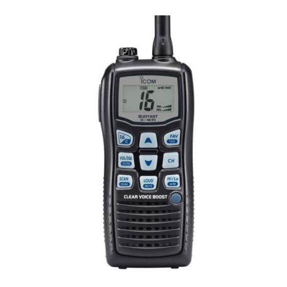
Page 10: Panel Description
PANEL DESCRIPTION ■ Front, top, side and rear panels q ANTENNA CONNECTOR (p. 2) Connects the supplied antenna. w SPEAKER-MICROPHONE CONNECTOR [SP MIC] (p. 25) Connects the optional external speaker-microphone. Function NOTE: Attach the [SP MIC] cap when the optional display speaker-microphone is not used. - Page 11 PANEL DESCRIPTION t VOLUME/SQUELCH/MONITOR KEY [VOL/SQL MONI] i FAVOURITE/TAG KEY [FAV TAG] ➥ Push to enter the volume adjustment mode and the ➥ Push this key to select the favourite (TAG) channels squelch adjustment mode. (pgs. 11, 12) with ignoring untagged channels in a channel group in sequence.
-
Page 12: Function Display
PANEL DESCRIPTION ■ Function display t LOCK INDICATOR (p. 13) Appears while the lock function is activated. y BATTERY INDICATOR Indicates remaining battery power. Indication Charging Battery level Full Middle No battery required blinks when the battery is over charged. blinks when the battery is exhausted. -
Page 13: Panel Description
PANEL DESCRIPTION !1 SQUELCH LEVEL INDICATOR !8 LOW POWER INDICATOR (p. 10) ➥ “LOW” appears when low power is selected. Shows the squelch level. ➥ “LOW” blinks when switching forced low power mode !2 VOLUME LEVEL INDICATOR because of a high temperature error or low voltage. ➥... -
Page 14: Basic Operation
BASIC OPERATION ■ Channel selection D Call channel IMPORTANT!: Prior to using the transceiver for the first time, the battery pack must be fully charged for optimum Each regular channel group has separate leisure-use call life and operation. To avoid damage to the transceiver, channels. - Page 15 BASIC OPERATION D U.S.A., International and ATIS channels The transceiver is pre-programmed with U.S.A.*, Interna- tional and ATIS † channels. These channel groups may be specifi ed for the operating area. * U.K. version only. German and Holland versions only. †...
-
Page 16: Receiving And Transmitting
BASIC OPERATION ■ Receiving and transmitting IMPORTANT: To maximize the readability of your trans- CAUTION: Transmitting without an antenna may damage the transceiver. mitted signal, pause a few sec. after pushing [PTT], hold the microphone 5 to 10 cm from your mouth and speak q Push and hold [ into the microphone at a normal voice level. -
Page 17: Call Channel Programming
BASIC OPERATION ■ Call channel programming ■ Adjusting the volume level Call channel is used to access Channel 16 (default; may The volume level can be adjusted with [VOL/SQL MONI] differ according to the version), however, you can program and [Y]/[Z]. the call channel with your most often-used channels in each q Push [VOL/SQL MONI] once to enter the volume adjust- channel group for quick recall. -
Page 18: Volume Loud Function
BASIC OPERATION ■ Volume loud function ■ Adjusting the squelch level The volume loud function can be activated temporarily by The squelch level can be adjusted with [VOL/SQL MONI] pushing [LOUD MUTE]. and [Y]/[Z]. In order to receive signals properly, as well as for the scan The function does not work when the volume level is 31. -
Page 19: Lock Function
BASIC OPERATION ■ Lock function ■ Automatic backlighting This function electronically locks all keys (except for [PTT], This function lights the function display and keys, and it is [VOL/SQL MONI], [LOUD MUTE], [Hi/Lo ] and [Y]/[Z]*) convenient for night-time operation. The automatic back- to prevent accidental channel changes and function access. -
Page 20: Scan Operation (Except Holland Version)
SCAN OPERATION (Except Holland version) ■ Scan types Set the TAG channels (scanned channels) before scanning. Scanning is an effi cient way to locate signals quickly over a wide frequency range. The transceiver has priority scan and Clear the TAG for unwanted channels which inconveniently stop scanning, such as those for digital communications. -
Page 21: Setting Tag Channels
SCAN OPERATION ■ Setting TAG channels ■ Starting a scan For more efficient scanning, add the desired channels as Set the priority scan function, scan resume timer and auto TAG channels or clear TAG for unwanted channels. scan function in advance, using the set mode. (p. 18) Channels that are not tagged will be skipped during scan- q Push and hold [CH] for 1 sec. -
Page 22: Dualwatch/Tri-Watch (Except Holland Version)
DUALWATCH/TRI-WATCH (Except Holland version) ■ Description ■ Operation q Select Dualwatch or Tri-watch in the set mode. (p. 19) Dualwatch monitors Channel 16 while you are receiving w Select the desired channel. on another channel; Tri-watch monitors Channel 16 and the e Push and hold [SCAN DUAL] for 1 sec. -
Page 23: Set Mode
SET MODE ■ Set mode programming D Set mode operation Set mode is used to change the conditions of transceiver's q Turn power OFF. functions: Beep tone function, Priority scan function , Scan † w While pushing [VOL/SQL MONI], turn power ON to enter resume timer †... -
Page 24: Set Mode Items
SET MODE ■ Set mode items D Beep tone function D Scan resume timer “bP” “St” (Not available with Holland version) Select the key touch beep sound from ON or US, or turn The scan resume timer can be set as a pause (OFF) or sound OFF. - Page 25 SET MODE D Dual/Tri-watch function D Automatic backlighting “dt” “bL” (Not available with Holland version) This function is convenient for night-time operation. The This item can be set as Dualwatch or Tri-watch. (p. 16) backlight can be selected from ON and OFF. •...
-
Page 26: Set Mode
SET MODE D Power save function D Low fi x function “PS” “LF” The power save function reduces current drain by deactivat- ( Appears only when the optional battery case is attached; not ing the receiver circuit for preset intervals. available with German version depending on the pre-setting.) •... -
Page 27: Battery Charging
Icom radios or Icom charger. Only Icom battery saltwater, or any other liquids. Never charge or use a wet pack is tested and approved for use and charge with Icom battery. If the battery gets wet, be sure to wipe it dry before radios or Icom charger. -
Page 28: D Charging Caution
If R DANGER! NEVER charge the battery pack in areas with any of these conditions occur, contact your Icom dealer or extremely high temperatures, such as near fires or stoves, distributor. -
Page 29: Supplied Battery Charger
BATTERY CHARGING ■ Supplied battery charger ■ Optional battery case ï Charging connections When you would like to use the optional AAA(LR03) size battery case (BP-251), install the batteries as illustrated Do not charge batteries other than the BP-252. below. Be sure to observe the correct polarity. q Attach the BC-173 to a fl... -
Page 30: Optional Battery Charger
BATTERY CHARGING ■ Optional battery charger D BC-162 installation D Charging q Connect the AC adapter as shown below. • To a desktop • To a wall w Insert the battery pack with/without the transceiver into Supplied screws Supplied screws the charger. -
Page 31: Optional Speaker-Microphone
OPTIONAL SPEAKER-MICROPHONE ■ HM-165 descriptions ■ Attachment Alligator type clip Turn power OFF before attaching the speaker-microphone. Then, insert the speaker-mic connector into the [SP MIC] To attach the speaker-mic. to your shirt or collar, etc. connector and carefully screw it tight, as shown below. Be careful not to cross-thread the connection. -
Page 32: Troubleshooting
TROUBLESHOOTING PROBLEM POSSIBLE CAUSE SOLUTION REF. The transceiver does not turn • The battery is exhausted. • Recharge the battery pack. p. 23 • The battery pack is not attached cor- • Attach the battery pack correctly. p. 3 rectly. No sound from speaker. -
Page 33: Vhf Marine Channel List
VHF MARINE CHANNEL LIST • International channels Frequency (MHz) Frequency (MHz) Frequency (MHz) Frequency (MHz) Frequency (MHz) Frequency (MHz) Transmit Receive Transmit Receive Transmit Receive Transmit Receive Transmit Receive Transmit Receive 156.050 160.650 156.550 156.550 157.050 161.650 156.125 160.725 156.625 156.625 157.125 161.725... -
Page 34: Specifications
SPECIFICATIONS ï GENERAL ï RECEIVER • Frequency coverage : Transmit 156.000–161.450 MHz • Receive system : Double-conversion superhetero- Receive 156.000–163.425 MHz dyne • Mode : FM (16K0G3E) • Sensitivity (20 dB SINAD) : –2 dBµ emf typical • Channel spacing : 25 kHz •... -
Page 35: Options
Battery case for 5 × AAA (LR03) alkaline cells. used with this transceiver. We are not responsible for the transceiver Output power level: 2 W at high (Depends on the pre-setting for being damaged or any accident caused when using non-Icom op- German version.) tional equipment. - Page 36 < Intended Country of Use > A-6711H-1EU-q Printed in Japan 2008 Icom Inc. © 1-1-32 Kamiminami, Hirano-ku, Osaka 547-0003, Japan Printed on recycled paper with soy ink.