Table of Contents
Advertisement
Quick Links
Copyright
This publication, including all photographs, illustrations and software, is protected un-
der international copyright laws, with all rights reserved. Neither this manual, nor any
of the material contained herein, may be reproduced without w ritten consent of the au-
thor.
Version 1.0
Disclaimer
The information in this document is subject to change without notice. The manufac-
turer makes no representations or warranties with respect to the contents hereof and
specifically disclaims any implied w arranties of merchantability or fitness for any par-
ticular purpose. The manufacturer reserves the right to revise this publication and to
make changes from time to time in the content hereof without obligation of the manu-
facturer to notify any person of such revision or changes.
Trademark Recognition
Microsoft, MS-DOS and Windows are registered trademarks of Microsoft Corp.
MMX, Pentium, Pentium-II, Pentium-III, Celeron are registered trademarks of Intel
Corporation.
Other product names used in this manual are the properties of their respective owners
and are acknowledged.
Federal Communications Commission (FCC)
This equipment has been tested and found to comply with the limits for a Class B digi -
tal device, pursuant to Part 15 of the FCC Rules. These limits are designed to provide
reasonable protection against harmful interference in a residential installation. This
equipment generates, uses, and can radiate radio frequency energy and, if not in-
stalled and used in accordance with the instructions, may cause harmful interference
to radio communications. However, there is no guarantee that interference will not oc-
cur in a particular installation. If this equipment does cause harmful interference to
radio or television reception, which can be determined by turning the equipment off
and on, the user is encouraged to try to correct the interference by one or more of the
following measures:
−
Reorient or relocate the receiving antenna.
−
Increase the separation between the equipment and the receiver.
−
Connect the equipment onto an outlet on a circuit different from that to which
the receiver is connected.
−
Consult the dealer or an experienced radio/TV technician for help.
Shielded interconnect cables and a shielded AC power cable must be employed with
this equipment to ensure compliance with the pertinent RF emission limits governing
this device. Changes or modifications not expressly approved by the system's manu-
facturer could void the user's authority to operate the equipment.
Preface
Advertisement
Table of Contents

Related Manuals for ECS P4IBAD2


Summary of Contents for ECS P4IBAD2
- Page 1 Preface Copyright This publication, including all photographs, illustrations and software, is protected un- der international copyright laws, with all rights reserved. Neither this manual, nor any of the material contained herein, may be reproduced without w ritten consent of the au- thor.
- Page 2 Declaration of Conformity This device complies with part 15 of the FCC rules. Operation is subject to the follow - ing conditions: − This device may not cause harmful interference, and − This device must accept any interference received, including interference that may cause undesired operation.
-
Page 3: Table Of Contents
Preface 錯誤! 尚未定義書籤。 Features and Packing List Translations CHAPTER 1 Introducing the Mainboard Introduction......................1 Checklist.........................1 Standard Items ....................1 Features........................2 Choosing a Computer Case................4 Mainboard Components..................5 CHAPTER 2 Installing the Mainboard Safety Precautions....................7 Quick Guide......................7 Installing the Mainboard in a Case..............8 Checking Jumper Settings...................8 Setting Jumpers .................... - Page 4 Advanced Chipset Features................32 Integrated Peripherals ..................34 Power Management Setup................37 PNP/PCI Configurations ................. 40 PC Health Status....................41 Frequency/Voltage Control................42 Load Fail-Safe Defaults Option ..............43 Load Optimized Defaults Option..............43 Set Supervisor/User Password................. 43 Save & Exit Setup Option................44 Exit Without Saving ..................
-
Page 5: Introducing The Mainboard
CD-in and a game port, as well as supporting Plug and Play. The P4IBAD2 incorporates the Intel i82845 (MCH) and the I n tel 82801BA (ICH2) chipsets, which supports 2.5V DDR DRAM, 2X/4X AGP (1.5V only), and the AC’... -
Page 6: Features
Each slot supports up to 1 GB with a total maximum capacity of 2 GB The P4IBAD2 includes a 4xAGP slot that provides four times the bandwidth of the original AGP specification. AGP technology pro- vides a direct connection between the graphics sub-system and the processor so that the graphics do not have to compete for processor time with other devices on the PCI bus. - Page 7 • Two IDE connectors which support four IDE channels and a floppy disk drive interface The P4IBAD2 supports Ultra DMA bus mastering with transfer rates of 33/66/100 MB/sec. Integrated I/O The mainboard has a full set of I/O ports and connectors: •...
-
Page 8: Choosing A Computer Case
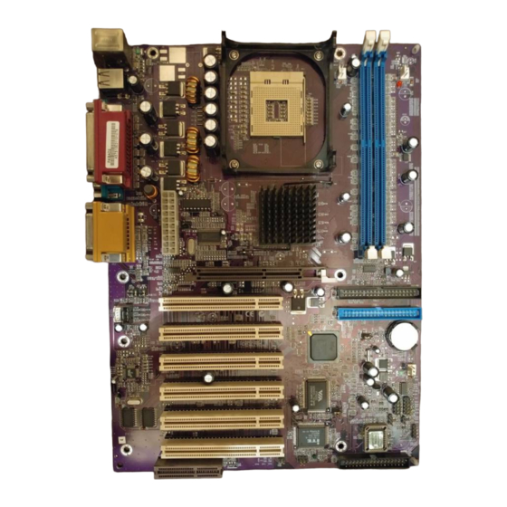
There are many types of computer cases on the market. The mainboard com- plies with the specifications for the ATX system case. Some features on the mainboard are implemented by cabling connectors on the mainboard to indi- cators and switches on the system case. Ensure that your case supports all the features required. - Page 10 Table of Mainboard Components Label Component AGP1 Accelerated Graphics Port (supports 1.5V 4x AGP card only) ATX1 Standard 20-pin ATX power connector AUDIO1 Mic/SpeakerOut header BAT1 Three volt realtime clock battery CASFAN1 Case fan connector CDIN1 CD-in connector (Panasonic) CDIN2 CD-in connector (Sony) CHS1 Chassis Detect Intrusion...
-
Page 11: Installing The Mainboard
Installing the Mainboard Follow these safety precautions when installing the mainboard: • Wear a grounding strap attached to a grounded device to avoid damage from static electricity. • Discharge static electricity by touching the metal case of a safely grounded object before working on the mainboard. •... -
Page 12: Installing The Mainboard In A Case
Refer to the following illustration and instructions for installing the mainboard in a case: This illustration shows an ex- 2. Secure the mainboard with ample of a mainboard being screws where appropriate. installed in a tower-type case: Note: Do not overtighten the screws as this can stress the main- board. -
Page 13: Checking Jumper Settings
Checking Jumper Settings The following illustration shows the location of the mainboard jumpers. Pin 1 is labeled. Jumper Settings Jumper Type Description Setting (default) 3-pin Clear CMOS 1-2: Normal J P 1 2-3: Clear 2-pin BIOS flash Short: Flash protect protection Open: Flash 3-pin... -
Page 14: Connecting Case Components
few seconds. JP2 – Enables you to prevent the BIOS from being updated (flashed). Open the jumper if you are going to update your BIOS. After updating the BIOS, short the jumper to protect the BIOS from being flashed. For ins tructions on updating the BIOS refer to Chapter 3. - Page 15 ATX1: ATX 20-pin Power Connector Signal Name Signal Name +3.3V +3.3V +3.3V -12V Ground Ground PS ON# Ground Ground Ground Ground Ground PWRGD +5VSB +12V SJI: Single-color LED header Signal Name ACPI LED ACPI LED 5VSB ACPI LED function: S4/S5 Light Blinking Blinking...
-
Page 16: Front Panel Connector
Front Panel Connector The front panel connector (PANEL1) provides a standard set of switch and LED connectors commonly found on ATX or micro-ATX cases. Refer to the table below for information: Signal Name Function HD_LED_P Hard disk LED pull up (330 ohm) to +5V FP PWR/SLP MSG LED pull up (330 ohm) to +5V HD_LED_N... -
Page 17: Installing Hardware
Installing the Processor Caution: When installing a CPU heatsink and cooling fan make sure that you DO NOT scratch the mainboard or any of the surface-mount resistors with the clip of the cooling fan. If the clip of the cooling fan scrapes across the mainboard, you may cause serious damage to the mainboard or its components. - Page 18 CPU Installation Procedure The following illustration shows CPU installation components: Note: The pin-1 corner is marked with an arrow Follow these instructions to install the Retention Module and CPU: Remove the existing retention module (if applicable). Position the backplate against the underside of the mainboard, secure the 4 screws firmly on the retention module.
- Page 19 Locate the CPU cut edge (the corner with the pinhole noticeably mis s- ing). Align and insert the CPU correctly. Press the lever down. Apply thermal grease on top of the CPU. Put the CPU Fan down on the retention module and s nap the four reten- tion legs of the cooling fan into place.
-
Page 20: Installing Memory Modules
Installing Memory Modules This mainboard accommodates 184-pin 2.5V unbuffered Double Data Rate (DDR) SDRAM memory modules. The memory chips must be standard or registered SDRAM (Synchronous Dynamic Random Access Memory). The mainboard can accommodate two memory modules. You must install at least one module in any of the two slots. -
Page 21: Installing A Hard Disk Drive/Cd-Rom
Installing a Hard Disk Drive/CD-ROM This section describes how to install IDE devices such as a hard disk drive and a CD-ROM drive. About IDE Devices Your mainboard has a primary and secondary IDE channel interface (IDE1 and IDE2). An IDE ribbon cable supporting two IDE devices is bundled with the main- board. -
Page 22: Installing A Floppy Diskette Drive
Installing a CD-ROM/DVD Drive Install the CD-ROM/DVD drive into the drive cage in your system case. Plug the IDE cable into IDE1 (A). If you have already installed an HDD, use the other connec- tor on the IDE cable. Note: Ribbon cable connectors are usually keyed so that they can only be installed correctly on the device connector. -
Page 23: Installing Add-On Cards
When you first start up your system, go immediately to the Setup Utility to configure the floppy diskette drives that you have installed. See Standard CMOS Features on page 28 for more information. Installing Add-on Cards This mainboard has six 32-bit PCI (Peripheral Components Interconnect) expansion slots, one 4xAGP slot, and one Communications and Networking Riser (CNR) slot. - Page 24 Follow these instructions to install an add-on card: Remove a blanking plate from the system case corresponding to the slot you are going to use. Install the edge connector of the add-on card into the expansion slot. Ensure that the edge con- nector is correctly seated in the slot.
-
Page 25: Connecting Optional Devices
Connecting Optional Devices Refer to the following for information on connecting the mainboard’ s optional devices: AUDIO1: Front Panel Audio header This header allows the user to install auxiliary front-oriented microphone and line-out ports for easier access. Signal Name Function AUD_MIC Front Panel Microphone input signal AUD_GND... - Page 26 USB1: Front panel USB connectors The mainboard has four USB ports installed on the rear edge I/O port array. Additionally, some computer cases have USB ports at the front of the case. If you have this kind of case, use auxiliary USB connectors USB1 to connect the front-mounted ports to the mainboard.
-
Page 27: Connecting I/O Devices
The backplane of the mainboard has the following I/O ports: Parallel port (LPT1) Game port PS/2 mouse PS/2 Serial port Serial port Microphone keyboard ports COM 1 COM 2 Line-in Line-out PS/2 Mouse Use the upper PS/2 port to connect a PS/2 pointing device. PS/2 Ke yboard Use the lower PS/2 port to connect a PS/2 keyboard. -
Page 28: External Connector Color Coding
External Connector Color Coding Many connectors now use standard colors as shown in the table below. Connector Color Audio line-in Light blue Audio line-out Lime Digital monitor/flat panel White IEEE 1394 Grey Microphone Pink MIDI/game Gold Parallel Burgundy PS/2-compatible keyboard Purple PS/2-compatible mouse Green... -
Page 29: Using Bios
Using BIOS The computer uses the latest Award BIOS with support for Windows Plug and Play. The CMOS chip on the mainboard contains the ROM setup instructions for configuring the mainboard BIOS. The BIOS (Basic Input and Output System) Setup Utility displays the system's configuration status and provides you with options to set system parameters. -
Page 30: Entering The Setup Utility
Entering the Setup Utility When you power on the system, BIOS enters the Power-On Self Test (POST) routines. POST is a series of built-in diagnostics performed by the BIOS. After the POST routines are completed, the following message appears: Press DEL to enter SETUP Pressing the delete key accesses the BIOS Setup Utility: Phoenix –... -
Page 31: Using Bios
If your mainboard has an item called Firmware Write Protect in Advanced BIOS features, disable it. (Firmware Write Protect prevents BIOS from being overwritten.) Create a bootable system disk. (Refer to Windows online help for info r- mation on creating a bootable system disk.) Download the Flash Utility and new BIOS file from the manufacturer's Web site. -
Page 32: Standard Cmos Features
Standard CMOS Features This option displays basic information about your system. Phoenix – AwardBIOS CMOS Setup Utility Standard CMOS Features Item Help Date (mm:dd:yy) Tue, July 11 2001 Time (hh:mm:ss) 12 : 8 : 59 Menu Level IDE Primary Master Change the day, month, IDE Primary Slave year and century. - Page 33 IDE HDD Auto-Detection Press <Enter> while this item is highlighted to prompt the Setup Utility to automatically detect and configure an IDE device on the IDE channel. Note: If you are setting up a new hard disk drive that supports LBA mode, more than one line will appear in the parameter box.
-
Page 34: Advanced Bios Features
Advanced BIOS Features This option defines advanced information about your system. Phoenix – AwardBIOS CMOS Setup Utility Advanced BIOS Features Item Help CPU L1 & L2 Cache [Enabled ] Quick Power On Self Test [Enabled] Menu Level First Boot Device [Floppy] Second Boot Device [HDD-0]... - Page 35 drive with 360K capacity. Boot Up NumLock Status (On) This item defines if the keyboard Num Lock key is active when your system is started. Gate A20 Option (Fast) This item defines how the system handles legacy software that was written for an earlier generation of processors.
-
Page 36: Advanced Chipset Features
Advanced Chipset Features These items define critical timing parameters of the mainboard. You should leave the items on this page at their default values unless you are very famil- iar with the technical specifications of your system hardware. If you change the values incorrectly, you may introduce fatal errors or recurring instability into your system. - Page 37 DRAM RAS# Precharge (3) Select the number of CPU clocks allocated for the Row Address Strobe (RAS#) signal to accumulate its charge before the DRAM is refreshed. If insufficient time is allowed, refresh may be incomplete and data lost. DRAM Data Integrity Mode (Non-ECC) Select Parity or ECC (error-correcting code), according to the type of installed DRAM.
-
Page 38: Integrated Peripherals
Integrated Peripherals These options display items that define the operation of peripheral compo- nents on the system's input/output ports. Phoenix – AwardBIOS CMOS Setup Utility Integrated Peripherals Item Help On-Chip Primary PCI IDE [Enabled ] IDE Primary Master [Auto] Menu Level IDE Primary Slave [Auto] IDE Primary Master... - Page 39 and Play. USB Mouse Support (Disabled) Enable this item if you plan to use a USB mouse. AC97 Audio (Auto) Enables and disables the onboard audio chip. Disable this item if you are go- ing to install a PCI audio add-on card. AC97 Modem (Auto) Enables and disables the onboard modem.
- Page 40 is Sharp's infrared communication protocol with a maximum baud rate up to 57.6K bps. UR2 Duplex Mode (Half) This field is available when UART 2 Mode is set to either ASKIR or IrDA. This item enables you to determine the infrared function of the onboard infrared chip.
-
Page 41: Power Management Setup
Power Management Setup This option lets you control system power management. The system has vari- ous power-saving modes including powering down the hard disk, turning off the video, suspending to RAM, and software power down that allows the sys- tem to be automatically resumed by certain events. The power-saving modes can be controlled by timeouts. - Page 42 the suspend mode is equivalent to a software power down. If you select S3 (STR), the suspend mode is a suspend to RAM, i.e., the system shuts down with the exception of a refresh current to the system memory. Power Management (User Define) This item acts like a master switch for the power-saving modes and hard disk timeouts.
- Page 43 Power On by Ring (Disabled) If this item is enabled, it allows the system to resume from a software power down or a power-saving mode whenever there is an incoming call to an installed fax/modem. You have to connect the fax/modem to the mainboard.
-
Page 44: Pnp/Pci Configurations
PNP/PCI Configurations These options configure how PnP (Plug and Play) and PCI expansion cards oper- ate in your system. Both the ISA and PCI buses on the Mainboard use system IRQs (Interrupt ReQuests) and DMAs (Direct Memory Access). You must set up the IRQ and DMA assignments correctly through the PnP/PCI Configurations Setup utility for the mainboard to work properly. -
Page 45: Pc Health Status
standard VGA cards. This board includes a built-in VGA system that does not require palette snooping so you must leave this item disabled. Assign IRQ For USB (Enabled) Names the interrupt request (IRQ) line assigned to the USB on your system. Activity of the selected IRQ always awakens the system. -
Page 46: Frequency/Voltage Control
Chassis Open Warning Enables or disables the alert warning message when the chassis has been opened. Frequency/Voltage Control This item enables you to set the clock speed and system bus for your system. The clock speed and system bus are determined by the kind of processor you have installed in your system. -
Page 47: Load Fail-Safe Defaults Option
Load Fail-Safe Defaults Option This option opens a dialog box that lets you install fail-safe defaults for all ap- propriate items in the Setup Utility: Press <Y> and then <Enter> to install the defaults. Press <N> and then <En- ter> to not install the defaults. The fail-safe defaults place no great demands on the system and are generally stable. -
Page 48: Save & Exit Setup Option
Save & Exit Setup Option Highlight this item and press <Enter> to save the changes that you have made in the Setup Utility and exit the Setup Utility. When the Save and Exit dialog box appears, press <Y> to save and exit, or press <N> to return to the main menu: Exit Without Saving Highlight this item and press <Enter>... -
Page 49: Using The Mainboard Software
Using the Mainboard Software The support software CD-ROM that is included in the mainboard package contains all the drivers and utility programs needed to properly run the bun- dled products. Below you can find a brief description of each software program, and the location for your mainboard version. -
Page 50: Running Setup
Setup Tab Setup Click the Setup button to run the software installation program. Select from the menu which software you want to install. Browse The Browse CD button is the standard Windows command that allows you to open Windows Explorer and show the contents of the support CD. - Page 51 Note: The following screens are examples only. The screens and driver lists will be different according to the mainboard you are installing. The mainboard identification is located in the upper left-hand corner. Click Next. The following screen appears: Check the box next to the items you want to install. The default options are recommended.
-
Page 52: Manual Installation
Insert the CD in the CD-ROM drive and locate the PATH.DOC file in the root directory. This file contains the information needed to locate the drivers for your mainboard. Look for the chipset and mainboard model; then browse to the directory and path to begin installing the drivers. - Page 53 We strongly recommend users to install this free anti-virus software to help protect your system against viruses. MediaRing Talk – Telephony Software To install the MediaRing Talk voice modem software for the built-in modem, go directory \UTILITY\MEDIARING TALK, then MRTALK- SETUP72.EXE to install the application software.